

Page 1

HP- 327
September 2018
Model: HIT-4U
Rate Indicator & Dual Totalizer
With Modbus & Data Logging
USER’S MANUAL
107 Kitty Hawk Lane ● P.O. Box 2145 ● Elizabeth City, NC 27909
1-800-628-4584 ● (252) 331-1997 ● Fax (252) 331-2886
www.hofferflow.com email: [email protected]
Flow-Tech, Inc. | In MD 410-666-3200 - In VA 804-752-3450 | www.flowtechonline.com
Page 2

HFC 9907-B
NOTICE
Hoffer Flow Controls, Inc. makes no warranty of any kind with regard to this
material, including, but not limited to, the implied warranties of merchantability and
fitness for a particular purpose.
This manual has been provided as an aid in installing, connecting, calibrating, operating,
and servicing this unit. Every precaution for accuracy has been taken in the
preparation of this manual; however, Hoffer Flow Controls, Inc. neither assumes
responsibility for any omissions or errors that may appear nor assumes liability for
any damages that result from the use of the products in accordance with information
contained in the manual.
HOFFER FLOW CONTROLS' policy is to provide a user manual for each item
supplied. Therefore, all applicable user manuals should be examined before
attempting to install or otherwise connect a number of related subsystems.
During installation, care must be taken to select the correct interconnecting wiring
drawing. The choice of an incorrect connection drawing may result in damage to the
system and/or one of the components.
Please review the complete model number of each item to be connected and locate the
appropriate manual(s) and/or drawing(s). Identify all model numbers exactly before
making any connections. A number of options and accessories may be added to the main
instrument, which are not shown on the basic user wiring. Consult the appropriate option
or accessory user manual before connecting it to the system. In many cases, a system
wiring drawing is available and may be requested from Hoffer Flow Controls.
This document contains proprietary information, which is protected by copyright. All
rights are reserved. No part of this document may be photocopied, reproduced, or
translated to another language without the prior written consent of Hoffer Flow
Controls, Inc.
HOFFER FLOW CONTROLS’ policy is to make running changes, not model
changes, whenever an improvement is possible. This affords our customers the latest
in technology and engineering. The information contained in this document is subject
to change without notice.
THIS WARRANTY IS EXPRESSLY IN LIEU OF ALL OTHER WARRANTIES,
EXPRESSED OR IMPLIED, INCLUDING ANY IMPLIED WARRANTY OF
MERCHANTABILITY OR FITNESS FOR A PARTICULAR PURPOSE. HFC
SHALL NOT BE
LIABLE FOR ANY LOSS OR DAMAGE RESULTING
, DIRECTLY OR INDIRECTLY,
FROM THE USE
OR LOSS OF USE OF THE GOODS
. WITHOUT LIMITING THE GENERALITY OF
THE FOREGOING
, THIS EXCLUSION FROM LIABILITY EMBRACES THE PURCHASER'S
EXPENSES FOR DOWNTIME OR FOR MAKING UP DOWNTIME
, DAMAGES FOR WHICH THE
PURCHASER MAY BE LIABLE TO OTHER PERSONS, DAMAGES TO PROPERTY, AND INJURY
TO OR DEATH OF ANY PERSONS
. HFC NEITHER ASSUMES NOR AUTHORIZES ANY PERSON
TO ASSUME FOR IT ANY OTHER LIABILITY IN CONNECTION WITH THE SALE OR USE OF
HFC'S GOODS, AND THERE ARE NO ORAL AGREEMENTS OR WARRANTIES COLLATERAL TO
OR AFFECTING THE AGREEMENT
. PURCHASER'S SOLE AND EXCLUSIVE REMEDY IS THE
REPAIR AND
/OR REPLACEMENT OF NONCONFORMING GOODS AS PROVIDED IN THE
PRECEDING PARAGRAPHS
. HFC SHALL NOT BE LIABLE FOR ANY OTHER DAMAGES
WHATSOEVER INCLUDING INDIRECT
, INCIDENTAL, OR CONSEQUENTIAL DAMAGES.
Flow-Tech, Inc. | In MD 410-666-3200 - In VA 804-752-3450 | www.flowtechonline.com
Page 3

HFC 9907-B
LIMITED WARRANTY POLICY FOR HOFFER FLOW CONTROLS
HOFFER FLOW CONTROLS, INC. ("HFC") warrants HFC's Precision Series, API Series and
CT Series of turbine flowmeters to be free from defects in material and workmanship under
normal use and service, only if such goods have been properly selected for the service intended,
properly installed and properly operated and maintained as described in the turbine flowmeter
manual. Reference "turbine flowmeter manual" for specific details. This warranty shall extend
for a period of five (5) years from the date of shipment to the original purchaser and covers the
Precision Series, API Series, and CT Series of flowmeters supplied with their standard hybrid
ceramic ball bearings only. All other HFC products carry a one (1) year warranty. This warranty
is extended only to the original purchaser ("Purchaser"). Purchaser's sole and exclusive remedy
is the repair and/or replacement of nonconforming goods as provided in the following
paragraphs.
In the event Purchaser believes the Hoffer product is defective, the product must be returned to
HFC, transportation prepaid by Purchaser, within the appropriate warranty period relative to the
product. If HFC's inspection determines that the workmanship or materials are defective and the
required maintenance has been performed and, has been properly installed and operated, the
product will be either repaired or replaced, at HFC's sole determination, free of additional
charge, and the goods will be returned, transportation paid by HFC, using a transportation
method selected by HFC.
Prior to returning the product to HFC, Purchaser must obtain a Returned Material Authorization
(RMA) Number from HFC's Customer Service Department within 30 days after discovery of a
purported breach of warranty, but not later than the warranty period; otherwise, such claims
shall be deemed waived. See the Return Requests/inquiries Section of this manual.
If HFC's inspection reveals the Hoffer product to be free of defects in material and workmanship
or such inspection reveals the goods were improperly used, improperly installed, and/or
improperly selected for service intended, HFC will notify the purchaser in writing and will
deliver the goods back to Purchaser upon receipt of Purchaser's written instructions and
agreement to pay the cost of transportation. If Purchaser does not respond within thirty (30)
days after notice from HFC, the goods will be disposed of in HFC's discretion.
HFC does not warrant the product to meet the requirements of any safety code of any state,
municipality, or other jurisdiction, and Purchaser assumes all risk and liability whatsoever
resulting from the use thereof, whether used singlely or in combination with other machines or
apparatus.
This warranty shall not apply to any HFC product or parts thereof, which have been repaired
outside HFC's factory or altered in any way, or have been subject to misuse, negligence, or
accident, or have not been operated in accordance with HFC's printed instructions or have been
operated under conditions more severe than, or otherwise exceeding, those set forth in the
specifications.
FOR NON-WARRANTY REPAIRS OR CALIBRATIONS, consult
HOFFER FLOW CONTROLS for current repair/calibration charges. Have
the following information available BEFORE contacting HOFFER FLOW
CONTROLS:
1. P.O. number to cover the COST of the repair/calibration,
2. Model and serial number of the product, and
3. Repair instructions and/or specific problems relative to the
product.
Flow-Tech, Inc. | In MD 410-666-3200 - In VA 804-752-3450 | www.flowtechonline.com
Page 4

HIT-4U HP-327
CONTENTS
1. INTRODUCTION ------------------------------------------1
Model Number Designation-------------------------------3
2. FEATURES AND SPECIFICATIONS-----------------7
2.1 General---------------------------------------------------8
2.2 Inputs-----------------------------------------------------9
2.3 DC Power/Loop Powered ----------------------------9
2.4 Analog Output------------------------------------------9
2.5 Pulse Output ------------------------------------------ 10
2.6 Alarm Output with Dual Set Point--------------- 10
2.7 Serial Port RS485------------------------------------ 10
2.8 Data Logging------------------------------------------ 10
2.9 Physical ------------------------------------------------ 10
3. INSTALLATION ----------------------------------------- 11
3.1 4-20 mA Current Loop ----------------------------- 18
3.2 Analog Output Update Time ---------------------- 19
3.3 Pulse Output ------------------------------------------ 20
3.4 Alarm Output----------------------------------------- 21
4. CONFIGURATION -------------------------------------- 23
4.1 Local Configuration--------------------------------- 23
4.2 Default Configuration------------------------------- 30
5. OPERATION ---------------------------------------------- 31
5.1 Front Panel-------------------------------------------- 31
5.2 Saving Total------------------------------------------- 31
5.3 Clearing the Total------------------------------------ 32
5.4 Displaying Logs--------------------------------------- 32
5.5 Fault Conditions ------------------------------------- 33
5.6 Battery Replacement-------------------------------- 33
6. MODBUS COMMUNICATIONS --------------------- 34
7. HIT-4 COMMUNICATION PROGRAM ----------- 43
8. MAINTENANCE ----------------------------------------- 55
Flow-Tech, Inc. | In MD 410-666-3200 - In VA 804-752-3450 | www.flowtechonline.com
Page 5

HP-327 HIT-4U
APPENDIX A – Declaration of Conformity ---------------- 57
APPENDIX B – Installation Drawings and Conditions
for Safe Use for Certified Systems------ 59
Flow-Tech, Inc. | In MD 410-666-3200 - In VA 804-752-3450 | www.flowtechonline.com
Page 6

Introduction 1
HIT-4U HP-327
1. INTRODUCTION
The HIT-4U is a battery, DC or loop-powered microprocessor-based
flow rate indicator and totalizer with data logger and Modbus
Communications Protocol. The instrument can accept a low-level
signal from a magnetic type pickup coil, a DC pulse signal, contact
closure or modulated carrier pickup (MCP/RF). Pulses from the signal
input are converted into volume and rate values based on flowmeter
calibration settings stored in the instrument. The total volume and flow
rate are displayed on a two-line liquid crystal display (LCD). A 4-20
mA analog signal proportional to the flowrate is output on the current
loop. The HIT-4U is configurable from the instrument front panel
keypad or via Modbus communications.
Figure 1 – HIT-4U Front Panel
Optional features include 20-point linearization to correct flow meter
non-linearity, a Scaled Pulse Output and Alarm Output configurable for
Rate or Total.
Enclosure options include NEMA 4X, panel mount, IP66 rated
aluminum and Ex d certified for hazardous areas. Most enclosure
options may be wall mounted or directly mounted on a flowmeter using
an optional riser.
HIT‐4
HOFFER FLOW CONTROLS , INC
ELIZABETH CITY , NC
M
WWW .HOFFERFLOW .COM
00000000
LOW BAT x 1000
00000
UNCOMPENSATED
GAL L
LB KG
A
CF M 3
SCF NM
3
BBL
/
MIN
/HR
/
DAY
Flow-Tech, Inc. | In MD 410-666-3200 - In VA 804-752-3450 | www.flowtechonline.com
Page 7

2 Introduction
HP-327 HIT-4U
This instrument is designed to conform to the EMC-Directive of the
Council of European Communities 89/336/EEC and the following
standards:
Generic Emission Standard EN 61000-6-3
Residential, Commercial & Light Industry Environment.
Generic Immunity Standard EN 61000-6-1
Residential, Commercial & Light Industry Environment.
Electrostatic discharge requirements EN 61000-4-2
Radiated, radio-frequency, electromagnetic immunity EN 61000-4-3
Electrical fast transient/burst requirements EN 61000-4-4
Immunity to conducted disturbances EN 61000-4-6
Flow-Tech, Inc. | In MD 410-666-3200 - In VA 804-752-3450 | www.flowtechonline.com
Page 8

Introduction 3
HIT-4U HP-327
MODEL NUMBER DESIGNATION
MODEL HIT-4( )
FLOW RATE INDICATOR/TOTALIZER
WITH MODBUS® COMMUNICATIONS PROTOCOL
MODEL HIT-4( A
)-( B )-( C )-( D )-( E )-( F )-( G )-( H )-( I )-( J )
TYPE
MODEL HIT-4( A
)-( )-( )-( )-( )-( )-( )-( )-( )-( )
OPTION
( A )
(U) UNCOMPENSATED
(G) GAS
ENCLOSURE STYLE
MODEL HIT-4(
)-( B )-( )-( )-( )-( )-( )-( )-( )-( )
OPTION
( B )
(2)* NEMA 4X ENCLOSURE (HIT-4U MOUNTED BEHIND ENCLOSURE)
(3)* ALUMINUM CASTING POWDER COATED ENCLOSURE (IP66)
(7)* STAINLESS STEEL ENCLOSURE (IP66)
(P) PANEL MOUNT ENCLOSURE (IP40)
(PD) PANEL MOUNT ENCLOSURE WITH CLEAR DOOR AND LOCK (IP40)
(PF) PANEL MOUNT ENCLOSURE WITH CLEAR FLEXIBLE PVC COVER
(IP65 FRONT ONLY
)
* OPTIONS FOR ENCLOSURE STYLE 3 AND 7
(_M) M20 CONDUIT THREAD. (NOT ALLOWED FOR USE IN CANADA)
(_S) SUNSHADE
TYPE
ENCLOSURE STYLE
INPUT POWER
PULSE INPUT
PULSE OUTPUT
ALARM
COMPENSATION METHOD
MOUNTING
COMMUNICATION PORT
SPECIAL FEATURES
Flow-Tech, Inc. | In MD 410-666-3200 - In VA 804-752-3450 | www.flowtechonline.com
Page 9

4 Introduction
HP-327 HIT-4U
INPUT POWER
MODEL HIT-4(
)-( )-( C )-( )-( )-( )-( )-( )-( )-( )
OPTION
( C )
(B) BATTERY POWERED
NOTE: MAG ONLY, NO ANALOG, PULSE, OR ALARM
(L) 2-WIRE, 4-20MA LOOP POWERED 8-30VDC
NOTE: MAG ONLY, NO PULSE OR ALARM
(D) 12 TO 30 VDC POWERED
NOTE: 4-20MA ANALOG OUT INCLUDED
(AC) AC POWERED UNIVERSAL 100-240VAC @ 0.15A 50/60 HZ
NOTE: NOT AVAILABLE FOR Ex d CERTIFIED SYSTEMS
4-20MA ANALOG OUT INCLUDED
PULSE INPUT
MODEL HIT-4(
)-( )-( )-( D )-( )-( )-( )-( )-( )-( )
OPTION
( D )
(M) MAGNETIC COIL, DRY CONTACT
(R) ISOLATED PULSE, RPM, RPR, HALL EFFECT COILS
(RF) MODULATED CARRIER COIL
PULSE OUTPUT
MODEL HIT-4(
)-( )-( )-( )-( E )-( )-( )-( )-( )-( )
OPTION
( E )
(5*) 0-5V TTL/CMOS
(OC*) OPEN COLLECTOR
* INSERT (R) FOR RAW FREQUENCY PULSE OUTPUT
NOTE: NOT AVAILABLE WITH (B) OR (L) POWER INPUTS
ALARM - WITH USER-DEFINED LEVELS FOR RATE AND/OR TOTAL
MODEL HIT-4(
)-( )-( )-( )-( )-( F )-( )-( )-( )-( )
OPTION
( F )
(5) 0-5V TTL/CMOS
(OC) OPEN COLLECTOR
NOTE: NOT AVAILABLE WITH (B) OR (L) POWER INPUTS
COMPENSATION METHOD-TEMP/PRESSURE LIQ/GAS
MODEL HIT-4(
)-( )-( )-( )-( )-( )-( G )-( )-( )-( )
OPTION
( G )
(X) NO COMPENSATION, ALWAYS USE X ON HIT-4U
DEFAULT TEMPERATURE / PRESSURE COMPENSATION ON HIT-4G
(TP1_) TEMPERATURE AND PRESSURE TRANSMITTER INPUTS (4-20MA)
(TP2_) 100 OHM RTD (DIN385) / PRESSURE TRANSMITTER INPUTS
(4-20MA)
Flow-Tech, Inc. | In MD 410-666-3200 - In VA 804-752-3450 | www.flowtechonline.com
Page 10

Introduction 5
HIT-4U HP-327
COMPRESSIBILITY OPTION
(_Z) ADD (Z) COMPRESSIBILITY SOFTWARE FOR GAS APPLICATIONS
EXCEEDING 50 PSIG. AT PRESSURES ABOVE 50 PSIG THE ERROR
DUE TO COMPRESSIBILITY WOULD BE GREATER THAN ± 1.0%
NOTE: COMPENSATION (TP, TPZ) NOT AVAILABLE WITH (B) OR
(L) POWER INPUTS
MOUNTING
MODEL HIT-4(
)-( )-( )-( )-( )-( )-( )-( H )-( )-( )
OPTION
( H )
(X) REMOTE MOUNTING
(FX) STYLE 3 OR 7 ENCLOSURES MOUNTED ON TURBINE. MUST BE USED
WITH “X” RISER TURBINE OPTION.
(FXHT) 8" LONG TEMPERATURE RISER FOR STYLE 3 OR 7 ENCLOSURE
MOUNTED ON TURBINE. REQUIRED WHEN TEMPERATURES EXCEEDS
140 DEG. F. MUST BE USED WITH “X” RISER TURBINE OPTION.
(F) NEMA 4X STYLE 2 ENCLOSURE MOUNTED ON TURBINE.
MUST BE USED WITH “X” RISER TURBINE OPTION.
(FHT) 8" LONG TEMPERATURE RISER FOR NEMA 4X STYLE 2 ENCLOSURES
MOUNTED ON TURBINE. REQUIRED WHEN FLUID TEMPERATURES
EXCEED 140 DEG. F. USED WITH “X” RISER TURBINE OPTION.
(NP) NEMA 4X ENCLOSURE PIPE MOUNTING KIT
2" PIPE OR SMALLER. SPECIFY IF PIPE IS VERTICAL OR HORIZONTAL.
SYSTEM CERTIFIED MOUNTING OPTIONS FOR ENCLOSURE STYLE 3 AND 7:
(MX_) METER MOUNTED
NOTE: USED WITH “X” RISER, AND 1" X ¾" SS ADAPTER.
PROCESS TEMP -40°C TO +78°C.
(MA_) METER MOUNTED
NOTE: USE WITH A (X-ATEX) RISER.
PROCESS TEMP -40°C TO +78°C.
(RX_) REMOTE MOUNTED
NOTE: USE WITH “X” RISER. INCLUDES “E2” JUNCTION BOX
AND 1" X 3/4" SS ADAPTER.
(RA_) REMOTE MOUNTED
NOTE: USE WITH A (X-ATEX) RISER. INCLUDES “E2” JUNCTION
BOX.
UNION OPTIONS:
(___U1) OPTIONAL 1" MALE X 1" FEMALE EX-PROOF UNION
NOTE: USE WITH MX AND RX OPTIONS
(___U2) OPTIONAL 3/4" MALE X 3/4" FEMALE EX-PROOF UNION
NOTE: USE WITH MA AND RA OPTIONS
Flow-Tech, Inc. | In MD 410-666-3200 - In VA 804-752-3450 | www.flowtechonline.com
Page 11

6 Introduction
HP-327 HIT-4U
SYSTEM CERTIFIED EXPLOSION-PROOF RATINGS:
STYLE 3 & 7: CSA/FM: CLASS I DIV. 1, GR. C,D; CLASS II, DIV. 1, GR. E,F,G;
CLASS III, T6; TYPE 4X;
CLASS I ZONE 1 AEx db IIB, T6 Gb IP66
ZONE 21 AEx tb IIIC T80°C Db IP66
Ex db IIB T6 Gb; Ex tb IIIC T80°C Db; IP66
- ATEX/IECEx: II 2 G Ex db IIB T6 Gb; IP66
II 2 D Ex tb IIIC T80°C Db; IP66
COMMUNICATION PORT
MODEL HIT-4-(
)-( )-( )-( )-( )-( )-( )-( I )-( )
OPTION
( I )
(T)* INTERNAL TERMINAL BLOCK
RS485/MODBUS, DATA LOGGING, CONFIGURATION AND MONITORING
RECOMMENDED FOR PERMANENT FIELD CONNECTION TO HIT-4X
ALL ENCLOSURES
(U)* EXTERNAL USB STYLE CONNECTOR
RS485/MODBUS FOR DATA LOGGING/CONFIGURATION
NEMA 4X ENCLOSURE ONLY
(X) NONE
SPECIAL FEATURES
MODEL HIT-4(
)-( )-( )-( )-( )-( )-( )-( )-( )-( J )
OPTION
( J )
CE) CE MARK REQUIRED FOR EUROPE (PENDING)
(SP) ANY SPECIAL FEATURES THAT ARE NOT COVERED IN THE
MODEL NUMBER USE A WRITTEN DESCRIPTION OF THE -SP.
(X) NO SPECIAL FEATURES
Flow-Tech, Inc. | In MD 410-666-3200 - In VA 804-752-3450 | www.flowtechonline.com
Page 12

Features and Specifications 7
HIT-4U HP-327
2. FEATURES AND SPECIFICATIONS
LCD display for Total and Rate
Non-resettable Grand Total
Full front panel operation with magnetic pointer via Ex
enclosure
Up to 20-Point Linearization to correct for flowmeter
non-linearity
4-20mA analog output proportional to flow rate
Optional Scaled Pulse Output representing an incremental
total volume
Alarm Output with dual set point configurable for Rate or
Total
Magnetically operated switch for Total reset
Internal battery pack backup
Configuration and Grand Total stored in non-volatile
memory. Total and Grand Total saved when pressing
►button.
Data Logging: Hourly Total, Daily Total, Event Logs
Modbus Communications Protocol via RS485
Real Time Clock
Flow-Tech, Inc. | In MD 410-666-3200 - In VA 804-752-3450 | www.flowtechonline.com
Page 13

8 Features and Specifications
HP-327 HIT-4U
2.1 General
Display: LCD, updated every 1 seconds.
Total: 8 digits 3/8" high. Resettable using a magnet, a
dry contact, from front panel keypad or via
Modbus communications.
Value is stored in non-volatile memory when
pressing ►button.
Total Units: GAL, LIT, FT3, ACF, ACFx1000, M3, BBL, KG,
LB, NM3, SCF, SCFx1000.
Grand Total: 8 digits 3/8" high, non-resettable. Value is stored
in non-volatile memory when pressing ►button.
Grand Total is displayed for 7 seconds after
pressing the
▲ button.
Rate: 6 digits 1/2" high.
Rate Units: /SEC, /MIN, /HR, /DAY
K-factor: The pulses per unit of Total (e.g. pulses/gallon)
are configurable in the range 0.001 to 9,999,999.
Linearization: 2-20 points.
Decimal Points: Decimal Point positions are configurable for 0,
0.0, 0.00, or 0.000 for rate, total and K-factor.
Accuracy: Total and Rate: 0.01% of reading, 1 Count
Flow-Tech, Inc. | In MD 410-666-3200 - In VA 804-752-3450 | www.flowtechonline.com
Page 14

Features and Specifications 9
HIT-4U HP-327
2.2 Inputs
Magnetic Pickup:
Frequency Range: 0.2 Hz to 5000 Hz.
Signal Level: 30 mV
P-P
to 30 V
P-P
.
Opto-Isolated DC Pulse:
Frequency Range: 0 Hz to 3000 Hz.
Signal Level: 0 to +DC pulse.
Internal Pull-Up 10 kΩ to +DC
Low (Logic 0): < 1 VDC
Min Pulse width: 0.1 msec
Contact Closure:
Frequency Range: 0 Hz to 5000 Hz
Internal Pull-up: 220 kΩ to +3.3 VDC
Reset:
Signal Type: Contact closure
Min Time On: 25 msec
Internal Pull-up: 35 kΩ to +3.3 VDC
External Magnet
MCP/RF Pickup
2.3 DC Power/Loop Powered
Voltage: 8 to 30 VDC
Current: < 24 mA
Loop Burden: 8 VDC maximum
Supply Backup: Two (C) Size Lithium or battery pack for
Ex systems
Battery Life: 2 years typical-Two (C) size battery
1 year typical-Ex system battery pack
Protection: Reverse polarity protected
2.4 Analog Output
Scale: 4 – 20 mA follows rate.
Accuracy: 0.02% of Full Scale @ 20ºC.
Temperature drift: 40 ppm/°C
Update Time: 0.125 seconds.
Protection: Reverse polarity protected
Flow-Tech, Inc. | In MD 410-666-3200 - In VA 804-752-3450 | www.flowtechonline.com
Page 15

10 Features and Specifications
HP-327 HIT-4U
2.5 Pulse Output
Type: 0-5V TTL, Open collector (30 VDC, 100 mA)
Divider: 0.01, 0.1, 1, 10, 100
Pulse Width: Adjustable 4ms to 300ms
Max Frequency: 100Hz
2.6 Alarm Output with Dual Set Point
Type: 0-5V TTL, Open collector (30 VDC, 100 mA)
Function: Rate or Total
2.7 Serial Port RS485
Protocol: Modbus RTU
Function: Data Logging, Configuration Process
Monitor
2.8 Data Logging
Hourly Total Log: 768
Daily Total Log: 378
Event Log: 345
Accessing Logs: Via Modbus communication
Up to 100 latest logs are viewable on the
front panel
2.9 Physical
Temperature: Operating: -40°F (-40C) to 158°F (70C).
Humidity: 0 – 90% Non-condensing.
Packaging: Explosion proof
(Approx. 5"x5"x5", 3 lbs.)
Flow-Tech, Inc. | In MD 410-666-3200 - In VA 804-752-3450 | www.flowtechonline.com
Page 16

Installation 11
HIT-4U HP-327
3. INSTALLATION
Warning: Do not open explosion-proof enclosure while
circuits are powered in hazardous locations.
Field wiring connections
All field wiring connections should be made using shielded cables.
The shield should be connected to the chassis ground lug on the HIT4U enclosure. The shield on the opposite end of the cable should be left
open. Connections are made to the HIT-4U terminal blocks using wire
gauges 26-16 AWG, tightening Torque 0.22 to 0.25Nm.
Accessing terminal block connections
Ex Enclosure:
1. Loosen the locking set screw using a 1/16" hex key (Allen
wrench) and unscrew the cover of the enclosure counterclockwise until it separates from the body of the enclosure.
2. Remove two #4-40 x 3/8" pan head screws from the front
panel by turning counter-clockwise.
3. Lift the display assembly from the enclosure. Terminal blocks
are on the bottom.
NEMA Enclosure:
1. Loosen, by turning counter-clockwise, the screws in each
corner of the enclosure cover to remove.
2. Remove four #4-40 thumb screws from the front panel by
turning counter-clockwise.
3. Lift the display assembly from the enclosure. Terminal blocks
are on the bottom.
Making connections to terminal blocks
1. Use a small flat blade screwdriver and turn counter-clockwise
to loosen the proper terminal screw.
2. Insert wire (26-16 AWG) and turn terminal screw clockwise to
tighten.
3. Lightly pull on wire to ensure proper connection.
Flow-Tech, Inc. | In MD 410-666-3200 - In VA 804-752-3450 | www.flowtechonline.com
Page 17

12 Installation
HP-327 HIT-4U
SW1
PCA192
HofferFlowControls
Tx A
Tx B
TB3
123456
TB2
Flow+
Flow‐
TB1
DC+
DC‐
Analog
Magnetic
Pickup
RS485
RS485
A
B
BatteryPoweredwithMagneticPickup
SW1
PCA192
HofferFlowControls
Tx A
Tx B
TB3
123456
TB2
Flow+
Flow‐
TB1
DC+
DC‐
Analog
Contact
Closure
RS485
RS485
BatteryPoweredwithContactClosure
Flow-Tech, Inc. | In MD 410-666-3200 - In VA 804-752-3450 | www.flowtechonline.com
Page 18

Installation 13
HIT-4U HP-327
SW1
PCA192
HofferFlowControls
Tx A
Tx B
TB3
123456
TB2
Flow+
Flow‐
TB1
DC+
DC‐
Analog
Load
+
‐
Magnetic
Pickup
RS485
RS485
A
B
Loop Powered with Magnetic Pickup
SW1
PCA192
HofferFlowControls
Tx A
Tx B
TB3
123456
TB2
Flow+
Flow‐
TB1
DC+
DC‐
Analog
Load
+
‐
Contact
Closure
RS485
RS485
Loop Powered with Contact Closure
Flow-Tech, Inc. | In MD 410-666-3200 - In VA 804-752-3450 | www.flowtechonline.com
Page 19

14 Installation
HP-327 HIT-4U
SW1
PCA192
HofferFlowControls
Pulse+
Pulse‐
Alarm+
Alarm‐
Tx A
Tx B
TB3
123456
TB2
Flow+
Flow‐
TB1
DC+
DC‐
Ana log
+
‐
RediPulse
Pickup
TTL(0‐5VDC)
Load
RS485
RS485
A
C
B
REG
DC Powered with Analog Output and
RediPulse Pickup (0-5V/TTL)
SW1
PCA192
HofferFlowControls
Pulse+
Pulse‐
Alarm+
Alarm‐
Tx A
Tx B
TB3
123456
TB2
Flow+
Flow‐
TB1
DC+
DC‐
Ana log
+
‐
RediPulse
Pickup
Open
Collector
Load
RS485
RS485
A
C
B
REG
DC Powered with Analog Output and
RediPulse Pickup (Open Collector)
Flow-Tech, Inc. | In MD 410-666-3200 - In VA 804-752-3450 | www.flowtechonline.com
Page 20

Installation 15
HIT-4U HP-327
SW1
PCA192
HofferFlowControls
Pulse+
Pulse‐
Alarm+
Alarm‐
Tx A
Tx B
TB3
123456
TB2
Flow+
Flow‐
TB1
DC+
DC‐
Ana log
+
‐
RediPulse
Pickup
Open
Collector
RS485
RS485
A
C
B
REG
*
*Jumperisrequiredif4‐20mAisnotconnected
DC Powered (no analog output) with
RediPulse Pickup (Open Collector)
SW1
PCA192
HofferFlowControls
Pulse+
Pulse‐
Alarm+
Alarm‐
Tx A
Tx B
TB3
123456
TB2
Flow+
Flow‐
TB1
DC+
DC‐
Ana log
4‐20mALoad
+
‐
Magnetic
Pickup
RS485
RS485
A
B
DC Powered with Analog Output
and Magnetic Pickup
Flow-Tech, Inc. | In MD 410-666-3200 - In VA 804-752-3450 | www.flowtechonline.com
Page 21

16 Installation
HP-327 HIT-4U
PCA192
Pulse+
Pulse‐
Alarm+
Alarm‐
Tx A
Tx B
TB3
TB2
Flow+
Flow‐
TB1
DC+
DC‐
Analog
4‐20mALoad
+
‐
MCP
Pickup
RS485
RS485
123456
SW1
J2
PCA193
TB1
A
B
DC Powered with Analog Output
and MCP/RF Pickup
Flow-Tech, Inc. | In MD 410-666-3200 - In VA 804-752-3450 | www.flowtechonline.com
Page 22

Installation 17
HIT-4U HP-327
RS485 Communications Port Wiring
1234 5
Communication Kit P/N: 800-0483
Flow-Tech, Inc. | In MD 410-666-3200 - In VA 804-752-3450 | www.flowtechonline.com
Page 23

18 Installation
HP-327 HIT-4U
Flowmeter Input
The flowmeter input accepts a low-level sinusoidal signal from a
magnetic type pickup coil, contact closure or DC pulse signal. An
optional circuit board (PCA193) provides an input that will accept a
signal from MCP/RF type pickups. Switches 1,2,3,4,5,6 on SW-1 must
be set according to the type of pickup coil to be used.
SW-1 SWITCH SETTINGS FOR FLOWMETER INPUT OPTIONS
INPUT OPTION SW-1 SETTINGS
Magnetic pickup
Contact Closure
1,2,3 - ON
4,5,6 - OFF
1 2 3 4 5 6
RediPulse
TTL
1,2,3,5 - OFF
4,6 - ON
1 2 3 4 5 6
RediPulse
Open Collector
*MCP/RF
1,2,3,6 - OFF
4,5 - ON
1 2 3 4 5 6
* PCA193 is required and J2 must be equipped for MCP/RF
3.1 4-20 mA Current Loop
When powered from a two-wire 4-20 mA current loop, a minimum
supply voltage in the range of 8-30 Volts DC is required, depending on
the loop load resistance. At nominal 250 Ohms loop resistance the
minimum power supply is 13V.
Backup batteries are included to ensure that volume accumulation will
not be interrupted during a power failure.
Flow-Tech, Inc. | In MD 410-666-3200 - In VA 804-752-3450 | www.flowtechonline.com
Page 24

Installation 19
HIT-4U HP-327
The HIT-4U outputs a 4-20mA analog signal that is proportional to the
calculated flow rate. The 4mA and 20mA settings referred to as OUT
LO and OUT HI respectively, may be configured from the front panel of
the instrument or via Modbus communications.
3.2 Analog Output Update Time
The displayed Rate and Total are updated once per second. The analog
output update time is 1/8 seconds. It takes about .25sec. to reach steady
state due to a change in the input.
When flow stops the time for the display to reach 0 and for the analog
output to return to 4 mA is between 0.25 and 8 seconds, depending on
the Sample Time setting (SMPL T). With the default setting the time is
0.25 seconds.
Changing the SMPL T is only recommended for low flow applications
where the input frequency is below 1 Hz. See Chapter 4 for more
information on Sample Time.
Supply Voltage VS Load
0
200
400
600
800
1000
1200
0 5 10 15 20 25 30
Supply Voltage
Load (Ohms)
Operating
Region
Flow-Tech, Inc. | In MD 410-666-3200 - In VA 804-752-3450 | www.flowtechonline.com
Page 25
20 Installation
HP-327 HIT-4U
3.3 Pulse Output
HIT-4U provides an optional Pulse Output factory configured for
turbine raw frequency or scaled pulse. The scaled pulse outputs one
pulse for the least significant digit of the displayed total. A scaling
factor of 0.01, 0.1, 1, 10 or 100 is available to reduce or increase the
resolution of the pulse output. For example, if the Total Decimal Point
is set to 0000000.0, and the Pulse Scale is 1, then 1 pulse will be output
for each tenth (0.1) of a unit of measure. Changing the Pulse Scale to
10, would result in an output pulse for each 1.0 unit of measure. The
output must be scaled so that the pulse frequency does not exceed
100Hz at the maximum flow rate.
The pulse width can be configured between 4 and 300ms.
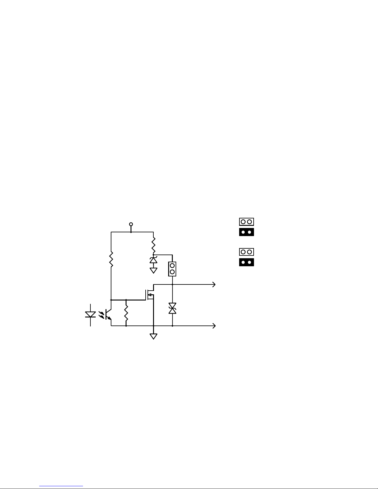
The Pulse Output may be configured as an Open Collector by removing
J9 or 0-5V (TTL/CMOS) by installing J9.
100K
100K
10K
OUT +
OUT -
+DC
*
*
PULSE OUT = J9
OR
ALARM OUT = J10
PULSE OUT
J9
OPEN COLL ECTO R
TTL/C MOS
ALARM OUT
J10
OPEN COLL ECTO R
TTL/C MOS
Pulse and Alarm Output
Flow-Tech, Inc. | In MD 410-666-3200 - In VA 804-752-3450 | www.flowtechonline.com
Page 26
Installation 21
HIT-4U HP-327
3.4 Alarm Output
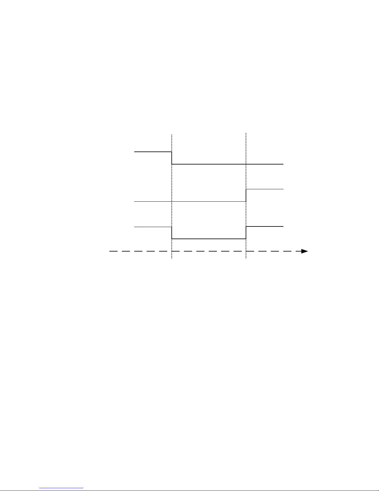
HIT-4U provides an optional Alarm Output configurable for Rate or
Total. The Alarm Output can be configured as Low Alarm, High
Alarm or Low/High.
Alarm Active – Output transistor is in OFF state
Alarm Not Active – Output transistor is in ON state
The Alarm Output may be configured as an Open Collector by
removing J10 or 0-5V (TTL/CMOS) by installing J10.
LowSet
Point
LowSet
Point
HighSet
Point
HighSet
Point
LOWALAR M
HIGHALARM
LO/HIALARM
Active
NotActive
NotActive
Active
ActiveActi ve NotActive
FlowRate
Flow-Tech, Inc. | In MD 410-666-3200 - In VA 804-752-3450 | www.flowtechonline.com
Page 27

22 Installation
HP-327 HIT-4U
This page intentionally left blank
Flow-Tech, Inc. | In MD 410-666-3200 - In VA 804-752-3450 | www.flowtechonline.com
Page 28

Configuration 23
HIT-4U HP-327
4. CONFIGURATION
The HIT-4U may be configured locally from the front panel, or
remotely using Hoffer HIT-4U Communication program or a Modbus
master. Front panel configuration may be done with magnetic pointer
through the glass cover, or pressing front panel keys when cover is off.
Do not remove cover in hazardous locations!
4.1 Local Configuration
M
00000000
LOW BAT x1000
00000
M
Enters Configuration Mode
Steps through each menu item.
Accepts entry when editing numeric values.
Saves Totals in Operate Mode
Scrolls through Menu Group
Scrolls though all values for each menu item.
Moves to the next digit to the right when editing numeric
values.
Displays Grand Total in Operate Mode Operate Mode
Returns to Operate Mode from Menu Group level.
Returns to Menu Group level from sub level menu.
Increments digit when editing numeric values.
Flow-Tech, Inc. | In MD 410-666-3200 - In VA 804-752-3450 | www.flowtechonline.com
Page 29
2 4 C o n f i g u r a t i o n
HP-327 HIT-4U
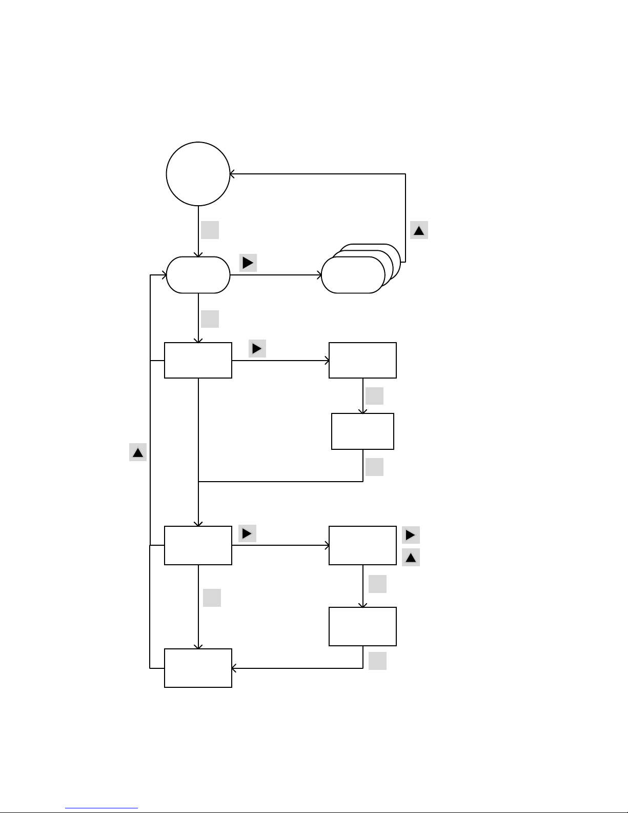
Examples of configuration steps to Clear Total, Set Total, and
displaying software version:
NO
Set Total
Done
Clear Total
OPE RATE
MODE
M
System
Menu
M
NO
Clear Total
Flow
Menu
YES
Clear Total
Enters Configurat ion
Mode
Next Menu
Gro up
Next Menu
Item
Next Option
M
Accepts
Selection
M
Next Menu
Item
Returns to
Operate Mode
10000000
Set Total
M
Accepts
Selection
Next Digit
Increaments Digit
10000000
Set Total
Software
Version
Next Option
M
Next Menu
Item
M
Next Menu
Item
Flow-Tech, Inc. | In MD 410-666-3200 - In VA 804-752-3450 | www.flowtechonline.com
Page 30
Configuration 25
HIT-4U HP-327
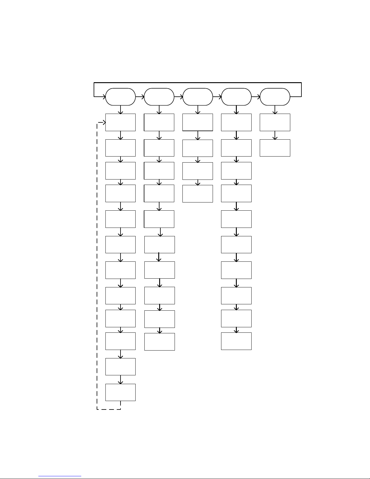
Configuration Menu Chart
System
Menu
Flow
Menu
Table
Menu
Output
Menu
Modbus
Menu
Clear
Total
Set
Total
Turbine
Serial #
Number of
points
Analog
Function
Modbus
Address
K Factor
Method
Frequency
2-20 points
Out
Low
Baud
Rate
Software
Version
K Factor
Decimal
K Factor
2-20 points
Out
High
Date
Average
K Factor
Pulse
Function
Time
Correction
Factor
Pulse
Width
ID
Number
Total
Decimal
Pulse
Scale
Password
Lock
Unit
Rate
Units
Alarm
Function
Rate
Decimal
Total
Set Point
Sample
Time
Low Cut off
Frequency
Rate Low
Set Point
Contract
Hour
Rate High
Set Point
Hourly
log
Daily
Log
Recal
Flow
Units
Flow-Tech, Inc. | In MD 410-666-3200 - In VA 804-752-3450 | www.flowtechonline.com
Page 31

2 6 C o n f i g u r a t i o n
HP-327 HIT-4U
Configuration Fields Description
SYSTEM MENU
Menu
Item
Description Options Min
Max
Value
Default
CLEAR
Clear Total and
save new value
(0) to EEPROM.
Grand Total is
non-resettable.
NO
YES
N/A NO
SETTOT
Set Total and
save to
EEPROM.
Numeric
Entry
0
99999999
0
SW VER
Read-only
displays HIT-4U
software version.
N/a N/A N/A
DATE
Current Date
(mm-dd-yy)
mm-dd-yy N/A 01-01-10
TIME
Current time in
24-hour format.
hh-mm-ss N/A 23-00-00
ID NUM
HIT-4U Serial
Number
Numeric
Entry
0
99999999
1234567
PASSWD Password
0000 –
9999
0000
9999
1234
LOCK
Password
protected
NO (0)
YES (1)
N/A NO
SMPL T
Sample
Time
1-80
1
80 (8 sec.)
1
CONTHR
Contract Hour
for daily logs
1-24 1 1 (1 AM)
HR LOG
Displays Hourly
Logs
Incremental
Scroll ►
1
(previous
hour)
99
0
(current)
DAYLOG
Displays Daily
Logs
Incremental
Scroll ►
1
(yesterday)
99
0
(current)
Flow-Tech, Inc. | In MD 410-666-3200 - In VA 804-752-3450 | www.flowtechonline.com
Page 32

Configuration 27
HIT-4U HP-327
FLOW MENU
Menu
Item
Description Options Min
Max
Value
Default
TURBIN Turbine serial #
Numeric
Entry
0000000
9999999
1234567
K FACT K Factor Method
Average
Table
N/A Average
KFAC D
The number of decimal
places for the K-Factor.
For Average K and K
Factors in table.
0
0.0
0.00
0.000
N/A 0.000
AVG K Average K Factor
Numeric
Entry
0.001
9999999.9
1.000
C FACT
Flow and total
multiplier
Numeric
Entry
0.001
99999.999
1.000
UNITS
Units of measure for
flow.
LB, KG, SCF,
SCFx1000, and NM3
have K-Factors
adjusted at fixed
temperature and
pressure
Gallons
Barrels
Liters
LB
KG
ACF
ACFx1000
SCF
SCFx1000
M3
NM3
N/A Gallons
TOTL D Total Decimal Point
0
0.0
0.00
0.000
N/A 0.0
RATE Time base for flow rate.
/sec
/min
/hour
/day
N/A /sec
RATE D Rate Decimal Point
0
0.0
0.00
0.000
N/A 0.0
CUTOFF
Low flow frequency
cutoff threshold in Hz.
Numeric
Entry
0.000
100.000
0.000
Flow-Tech, Inc. | In MD 410-666-3200 - In VA 804-752-3450 | www.flowtechonline.com
Page 33

2 8 C o n f i g u r a t i o n
HP-327 HIT-4U
TABLE MENU
Menu
Item
Description Options Min
Max
Value
Default
RECAL
Restores K-Factor
table to factory
default values to
allow entry of new
calibration data.
NO
YES
N/A NO
POINTS Number of points 2-20 2
20
10
FR 01
Frequency points
2 – 20. Follow
monotonic and
separation rules.
Numeric
Entry
0.001
5000.000
Fr20 =
5000.000
Fr19=
4999.999
Fr18
=49999.998
ETC.
K 01
K factor points 2 20
Numeric
Entry
0.001
9999999.9
1.000
MODBUS MENU
Menu Item
Description Options Min
Max
Value
Default
ADDRSS Modbus address Numeric
entry
000-254
BAUD
Baud rate for
RS485
*9600
57600
115200
N/A 9600
*Currently fixed at 9600.
Flow-Tech, Inc. | In MD 410-666-3200 - In VA 804-752-3450 | www.flowtechonline.com
Page 34

Configuration 29
HIT-4U HP-327
OUTPUT MENU
Menu Item
Description Options Min
Max
Value
Default
ANALOG
Analog Out
Function.
OFF
RATE
4mA
12mA
20mA
N/A OFF
OUT LO
4 mA setting in
units selected
for Total .
OUT LO must
be < OUT HI.
Numeric
Entry
0.000
999998
0.000
OUT HI
20 mA setting in
units selected
for Total. OUT
HI must be >
OUT LO.
Numeric
Entry
0.001
999999
100.000
PULSE
Pulse Function OFF
ON
TEST
N/A OFF
WIDTH
Pulse width in
mS
Numeric
Entry
4 ms
300 ms
4 ms
SCALE
Pulse Scale.
This factor
represents the
number of
output pulses
per least
significant digit
of displayed
total determined
by the total
decimal
selection.
0.01
0.1
1
10
100
N/A 1
Flow-Tech, Inc. | In MD 410-666-3200 - In VA 804-752-3450 | www.flowtechonline.com
Page 35

3 0 C o n f i g u r a t i o n
HP-327 HIT-4U
ALARM
Alarm function. OFF
RATE LO
RATE HI
RATE LOHI
TOTAL
TEST
N/A OFF
TOTSET Total alarm set
point.
Numeric
Entry
0.001
9999999
1000.00
LO SET
Rate alarm low
set point.
Numeric
Entry
0
999999
10.00
HI SET
Rate alarm high
set point.
Numeric
Entry
0
999999
100.00
4.2 Default Configuration
HIT-4U is fully configured by the factory prior to shipment. When the
instrument is purchased with a Hoffer Flowmeter or when calibration
and configuration data are supplied, the instrument is configured as
specified. When calibration or configuration data is not available, the
instrument is shipped with default values. Refer to the above table for
a listing of the HIT-4U factory default configuration.
Flow-Tech, Inc. | In MD 410-666-3200 - In VA 804-752-3450 | www.flowtechonline.com
Page 36
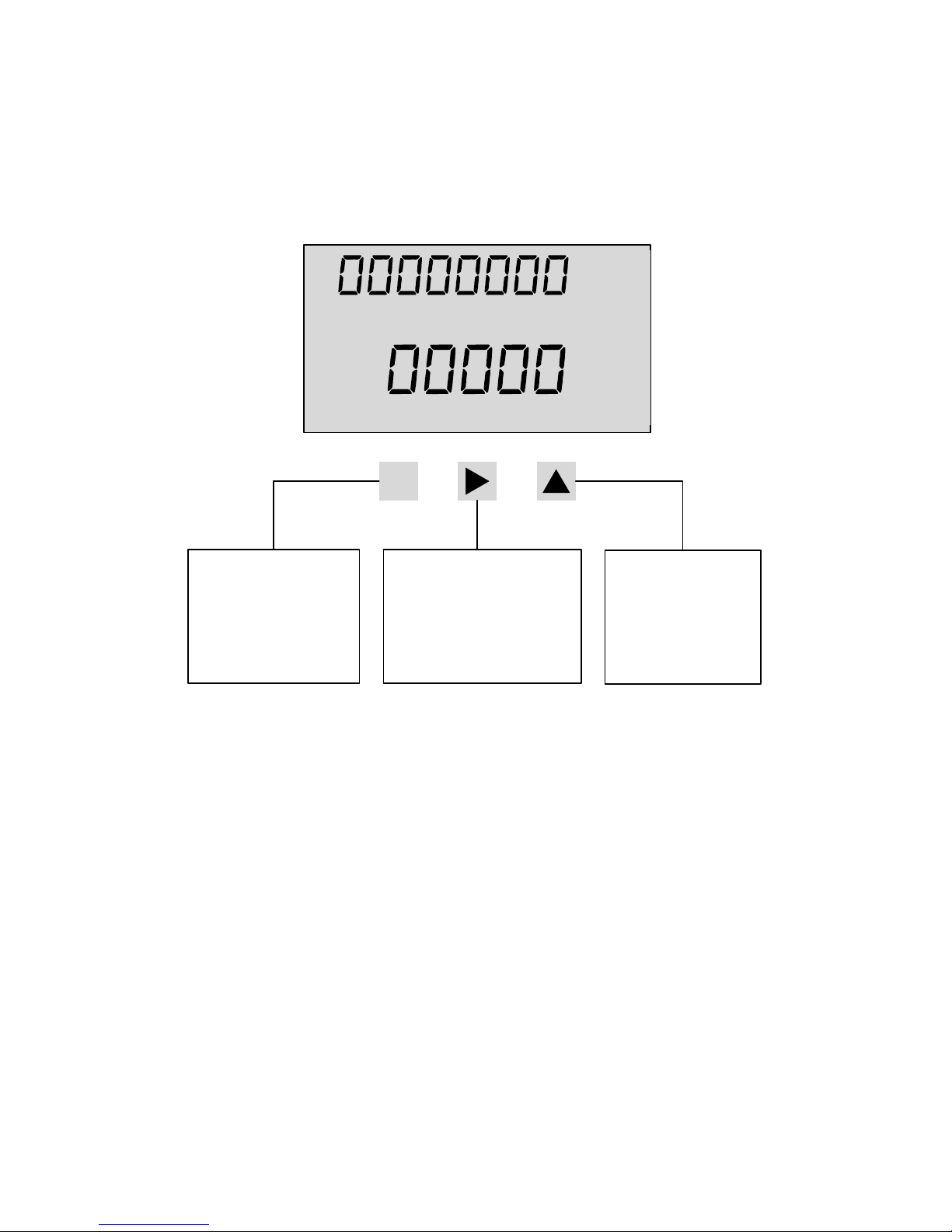
Operation 31
HIT-4U HP-327
5. OPERATION
5.1 Front Panel
The HIT-4U displays flow total and flow rate on a two-line liquid
crystal display (LCD). The display is updated once per second. The
8-digit non-resettable Grand Total can be viewed on the top line
by pressing ▲ key. The Grand Total is displayed for approximately 7
seconds before returning to the Total display.
5.2 Saving Total
Total and Grand Total can be saved at any time by pressing ► button.
When changing the battery (see section 5.6 Battery Replacement), it is
recommended to stop the flow and save Total prior to removing power
from the unit.
M
LOW BAT x1000
UNCOMPENSATED
GAL L
LB KG
ACF M3
SCF NM3
BBL
/MIN
/HR
/DAY
Total
Rate
Operate Mode:
Enters Configuration
Mode
Configuration Mode:
Scrolls through menus
Accepts numerical entry
Operate Mode:
Saves Totals
Configuration Mode:
Selects group of menus
Selects value for each menu
Moves to the next digit
Operate Mode:
Displays Grand Total
Configuration Mode:
Moves one level up
Increments digits
Flow-Tech, Inc. | In MD 410-666-3200 - In VA 804-752-3450 | www.flowtechonline.com
Page 37
Operation 32
HP-327 HIT-4U
5.3 Clearing the Total
The Flow Total may be cleared by using a magnetic pointer, a contact
closure to power common on the RESET input terminal, from the front
panel key, or via Modbus communications (See Chapter 6 Modbus
Communications).
To clear the total using a magnetic pointer, slide the magnet slowly
across the HIT-4U model name at the top of the front panel overlay.
To reset the total from the front panel keypad, use the following key
sequence:
Press M SYSTEM MENU is displayed
Press M CLEAR NO is displayed
Press
►
CLEAR YES is displayed
Press M
CLEAR DONE is displayed
Press ▲
To return to SYSTEM MENU
Press ▲
To return to operating mode
5.4 Displaying Logs
HIT-4U records up to 768 hourly logs, 378 daily logs and 345 event
logs. Data logs can be red via Modbus. The newest 99 Hourly and
Daily logs can be displayed on the front panel by accessing the Log
Menu. Event logs can be read only via Modbus.
Logs Screen
OOOOO234
O1 34
Flow
Total
Flow Time
Minutes for Hourly Logs
Hours for Daily Logs
Log
Number
Flow-Tech, Inc. | In MD 410-666-3200 - In VA 804-752-3450 | www.flowtechonline.com
Page 38

Operation 33
HIT-4U HP-327
To access Hourly Logs
Press M
12 times
HR LOG is displayed
Press
►
The last recorded log is displayed
Press
►
Previous log is displayed
Press ▲
To return to SYSTEM MENU
Press ▲
To return to operating mode
To access Daily Logs
Press M
13 times
DAY LOG is displayed
Press
►
The last recorded log is displayed
Press
►
Previous log is displayed
Press ▲
To return to
SYSTEM MENU
Press ▲
To return to operating mode
5.5 Fault Conditions
The HIT-4U detects numerous system faults and sends error message
via Modbus. (Refer to Chapter 6. Modbus Communications.)
5.6 Battery Replacement
The HIT-4U monitors the battery voltage and displays LOW BAT on the
LCD when the battery is approaching the end of its life (3V).
The Total and Grand Total are not saved automatically when power is
removed from the HIT-4U.
When changing the battery, it is recommended to stop the flow and
save Total prior to removing power from the unit.
Flow-Tech, Inc. | In MD 410-666-3200 - In VA 804-752-3450 | www.flowtechonline.com
Page 39

Operation 34
HP-327 HIT-4U
This page intentionally left blank
Flow-Tech, Inc. | In MD 410-666-3200 - In VA 804-752-3450 | www.flowtechonline.com
Page 40

Modbus Communications 35
HIT-4U HP-327
6. MODBUS COMMUNICATIONS
HIT Com Software or a Modbus Master may be used to configure HIT4U,
monitor process variables and obtain diagnostic information from
the
HIT-4U.
Supported Commands
Function Code
(Hex)
Description
03 Read holding registers
05 Preset Boolean (for Enron event record
acknowledgement
10 Write Commands
Data Types
* The variables Rate, Total and Grand Total are available as single 32 or
64-bit registers as well as multiple 16-bit registers.
Registers
Each register is labeled as Read Only (RO) or Read/Write (R/W)
according to access type.
Register
(Decimal)
Description
Data
Type
Access Notes
1 Clear Event
Logs
U16 RO
3 Clear Hourly
Logs
U16 RO
5 Clear Daily
Logs
U16 RO
7 Clear Grand
Total
U16 RO
9 Clear Total U16 RO Send a read request
to this register to
clear Total
Data Type Byte Count Register Count
Unsigned Int (U16) 2 1
Unsigned Int (U32) 4 1
Floating Point (FP32) 4 *1 or 2
Double Precision Float (FP64) 8 *1 or 4
Flow-Tech, Inc. | In MD 410-666-3200 - In VA 804-752-3450 | www.flowtechonline.com
Page 41

Modbus Communications 36
HP-327 HIT-4U
Register
(Decimal)
Description
Data
Type
Access Notes
32 Request Event
Logs
U16
(2)
FP32
(4)
RO
700 Request Hourly
Logs
FP32
(4)
RO
701 Request Daily
Logs
FP32
(4)
RO
1002 Software
Version
FP32 RO
1003 Device Type U16 RO 0=4U, 1=4G, 2=4L
1005 Turbine Serial
Number
U32 R/W 1 – 99999999
1006 Electronic ID
Number
U32 R/W 1 – 99999999
1007 Password U16 R/W 0000-9999
1008 Lock Unit U16 R/W 0=No, 1=Yes
1009 Slave Address U16 R/W 0-253
1010 Baud Rate U16 R/W 0 = 9600, 1 = 57000,
2 = 115200
1011 Sample Time U16 R/W 1-80
1013 Contract Hour U16 R/W 1-24
1200 Year U16 R/W 0-99
1201 Month U16 R/W 1-12
1202 Day U16 R/W 1-31
1203 Hour U16 R/W 1-24
1204 Minute U16 R/W 0-59
1205 Second U16 R/W 0-59
2000 Total Units U16 R/W 0=gal, 1=bbl, 2=L,
3=lb, 4=kg, 5=acf,
6=acfx1000, 7=scf,
8=scfx1000, 9=m3,
10=nm3
Flow-Tech, Inc. | In MD 410-666-3200 - In VA 804-752-3450 | www.flowtechonline.com
Page 42

Modbus Communications 37
HIT-4U HP-327
Register
(Decimal)
Description
Data
Type
Access Notes
2001 Total Decimal
Point
U16 R/W 0-3
2003 Rate Time Base U16 R/W 0=sec, 1=min, 2=hr,
3=day
2004 Rate Decimal
Point
U16 R/W 0-3
2005 K-Factor
Method
U16 R/W 0=Average,
1=Linear
2006 Average K-
Factor
FP32 R/W 0.001-9999999
2007 Low Frequency
Cutoff
U16 R/W 0-100 Hz
2008 K-Factor
Number of
Points
U16 R/W 2-20
2010 K-Factor
Decimal Point
U16 R/W 0-3
2011 Frequency 1 FP32 R/W 0.001-5000.000
2013 Frequency 2 FP32 R/W 0.001-5000.000
2015 Frequency 3 FP32 R/W 0.001-5000.000
2017 Frequency 4 FP32 R/W 0.001-5000.000
2019 Frequency 5 FP32 R/W 0.001-5000.000
2021 Frequency 6 FP32 R/W 0.001-5000.000
2023 Frequency 7 FP32 R/W 0.001-5000.000
2025 Frequency 8 FP32 R/W 0.001-5000.000
2027 Frequency 9 FP32 R/W 0.001-5000.000
2029 Frequency 10 FP32 R/W 0.001-5000.000
2031 Frequency 11 FP32 R/W 0.001-5000.000
2033 Frequency 12 FP32 R/W 0.001-5000.000
2035 K-Factor 1 FP32 R/W 0.001-9999999
2037 K-Factor 2 FP32 R/W 0.001-9999999
2039 K-Factor 3 FP32 R/W 0.001-9999999
2041 K-Factor 4 FP32 R/W 0.001-9999999
2043 K-Factor 5 FP32 R/W 0.001-9999999
2045 K-Factor 6 FP32 R/W 0.001-9999999
2047 K-Factor 7 FP32 R/W 0.001-9999999
2049 K-Factor 8 FP32 R/W 0.001-9999999
2051 K-Factor 9 FP32 R/W 0.001-9999999
2053 K-Factor 10 FP32 R/W 0.001-9999999
2055 K-Factor 11 FP32 R/W 0.001-9999999
2057 K-Factor 12 FP32 R/W 0.001-9999999
Flow-Tech, Inc. | In MD 410-666-3200 - In VA 804-752-3450 | www.flowtechonline.com
Page 43

Modbus Communications 38
HP-327 HIT-4U
Register
(Decimal)
Description
Data
Type
Access Notes
2059 Frequency 13 FP32 R/W 0.001-5000.000
2061 Frequency 14 FP32 R/W 0.001-5000.000
2063 Frequency 15 FP32 R/W 0.001-5000.000
2065 Frequency 16 FP32 R/W 0.001-5000.000
2067 Frequency 17 FP32 R/W 0.001-5000.000
2069 Frequency 18 FP32 R/W 0.001-5000.000
2071 Frequency 19 FP32 R/W 0.001-5000.000
2073 Frequency 20 FP32 R/W 0.001-5000.000
2075 K-Factor 13 FP32 R/W 0.001-9999999
2077 K-Factor 14 FP32 R/W 0.001-9999999
2079 K-Factor 15 FP32 R/W 0.001-9999999
2081 K-Factor 16 FP32 R/W 0.001-9999999
2083 K-Factor 17 FP32 R/W 0.001-9999999
2085 K-Factor 18 FP32 R/W 0.001-9999999
2087 K-Factor 19 FP32 R/W 0.001-9999999
2089 K-Factor 20 FP32 R/W 0.001-9999999
4000 Pulse Function U16 R/W 0=off, 1=on, 2=test
4001 Pulse Width
(mS)
U16 R/W 4-300mS
4003 Pulse Scale U16 R/W 0=0.01, 1=0.1, 2=1,
3=10, 4=100
4005 Analog Out
Function
U16 R/W 0=off, 1=rate,
2=4mA, 3=12mA,
4=20mA
4007 Analog Out Low FP32 R/W 0.000-999998
4009 Analog Out
High
FP32 R/W 0.001-999999
4011 Alarm Function U16 R/W 0=off, 1=rate lo,
2=rate hi 3=rat lohi,
4=total, 5=test
4012 Total Alarm Set
Point
FP64 R/W 0.001-99999999
4013 Rate Alarm Low
Set Point
FP32 R/W 0.001- Max limited
by rate decimal
point selection:
999.999, 9999.99,
99999.9, 99999
Flow-Tech, Inc. | In MD 410-666-3200 - In VA 804-752-3450 | www.flowtechonline.com
Page 44

Modbus Communications 39
HIT-4U HP-327
Register
(Decimal)
Description
Data
Type
Access Notes
4014 Rate Alarm
High Set Point
FP32 R/W 0.001- Max limited
by rate decimal
point selection:
999.999, 9999.99,
99999.9, 99999
7000 Request Hourly
Log Pointer
FP32 RO -1 (cleared logs) -
767
7001 Request Daily
Log Pointer
FP32 RO -1 (cleared logs) -
383
7002 Request Event
Log Pointer
FP32 RO 0-344
7003 Request Date FP32 RO 010100 - 123199
7004 Request Time FP32 RO 000000 - 235959
7005 Request Grand
Total
FP64 RO 0 – 99999999
16-bit registers
available at
address 7056-7059
(FP64) and 7062-
7063 (FP32)
7006 Request Rate FP32 RO 0 – Max limited by
rate decimal point
selection: 999.999,
9999.99, 99999.9,
99999
16-bit registers
available at
address 7050-7051
7007 Request Daily
Total
FP64 RO 0 – 99999999
7008 Request Daily
Run Time
Seconds
FP32 RO 0 – 86400
7009 Request Hourly
Total
FP64 RO 0 – 99999999
7010 Request Hourly
Run Time
Seconds
FP32 RO 0 – 3600
Flow-Tech, Inc. | In MD 410-666-3200 - In VA 804-752-3450 | www.flowtechonline.com
Page 45

Modbus Communications 40
HP-327 HIT-4U
Register
(Decimal)
Description
Data
Type
Access Notes
7011 Request Current
Total
FP64 R/W 0 – Max limited by
total decimal point
selection:
99999.999,
999999.99,
9999999.9,
99999999.
This register is also
used to clear total by
writing 0 or set total
by writing desired
value.
16-bit registers
available at
address 7052-7055
(FP64) and 7060-
7061 (FP32)
7013 Request
Previous Day
Total
FP64 RO 0 – 99999999
7014 Request
Previous Day
Run Time
Seconds
FP32 RO 0 – 86400
7015 Request
Previous Hour
Total
FP64 RO 0 – 99999999
7016 Request
Previous Hour
Run Time
Seconds
FP32 RO 0 - 3600
7018 Request Hourly
Download
Pointer
FP32 RO -1 (cleared logs) -
767
7019 Request Daily
Download
Pointer
FP32 RO -1 (cleared logs) -
383
Flow-Tech, Inc. | In MD 410-666-3200 - In VA 804-752-3450 | www.flowtechonline.com
Page 46

Modbus Communications 41
HIT-4U HP-327
Register
(Decimal)
Description
Data
Type
Access Notes
7020 Request Event
Log Download
Pointer
FP32 R/W -1 (cleared logs) –
344 (To increment
by one, use function
code 5)
7022 Fault History U32 RO Fault has occurred
since last power on.
Each bit represents a
specific fault
defined below.
7023 Active Faults U32 RO Fault is currently
active. Each bit
represents a specific
fault defined below.
7050-
7051
Request Rate FP32 RO Rate stored in two
16-bit registers
7052-
7055
Request Current
Total
FP64 RO Current Total stored
in four 16-bit
registers
Total is reset by
sending a read
request to register 9.
7056-
7059
Request Grand
Total
FP64 RO Grand Total stored
in four 16-bit
registers
7060-
7061 *
Request Current
Total
FP32 RO Current Total stored
in two 16-bit
registers
Total is reset by
sending a read
request to register 9.
7062-
7063
*
Request Grand
Total
FP32 RO Grand Total stored
in two 16-bit
registers
* NOTE – The Total and Grand Total values are available in 3 formats: 64-bit
in a single register, 64-bit in four consecutive 16-bit registers and 32-bit in
two consecutive 16-bit registers. The 64-bit format is recommended for
greater precision, especially with values greater than 7-digits.
Flow-Tech, Inc. | In MD 410-666-3200 - In VA 804-752-3450 | www.flowtechonline.com
Page 47

Modbus Communications 42
HP-327 HIT-4U
Fault Codes
The following table defines each bit for the fault codes returned when
polling register 7022 and 7023 using function code 03. When a value of 1
is returned for a bit, it indicates that the fault has occurred since last power
on (7022) or is currently active (7023).
Bit Fault
0 Reset, brownout
1 Reset, reset pin
2 Reset, DoBOR
3 Reset, wakeup from LPM5
4 Reset, security violation
5 Reset, supply voltage supervisor low
6 Reset, supply voltage supervisor high
7 Reset, supply voltage monitor low
8 Reset, supply voltage monitor high
9 Reset, DoPOR
10 Reset, watchdog timer timeout
11 Reset, watchdog timer key violation
12 Reset, flash key violation
13 Reset, PLL unlock
14 Reset, peripheral/configuration area fetch
15 Reset, power management key violation
16 Low battery
17 Pulse output overflow
18 Alarm, rate low
19 Alarm, rate high
20 Alarm, total
21 Flash segment 1 invalid
22 Flash segment 2 invalid
23 Maximum input frequency exceeded
24 EEPROM read error on startup
25 Code execution error
26 Flow rate exceeds 20mA setting
27 Spare 5
28 Spare 4
29 Spare 3
30 Spare 2
31 Spare 1
Flow-Tech, Inc. | In MD 410-666-3200 - In VA 804-752-3450 | www.flowtechonline.com
Page 48

HIT-4 Communication Program 43
HIT-4U HP-327
7. HIT-4 COMMUNICATION PROGRAM
Introduction
Hoffer’s HIT-4 Communication Program allows user to configure HIT-4
devices, monitor process variables, read data logs, and obtain diagnostic
information from the HIT-4.
The program can be run without HIT-4 device connected to view and
edit previously saved configuration files and data log files.
System Requirements
PC Windows XP, 7
Installation
Running the HIT-4 Communication Program
Connect HIT-4 device to a computer with either a RS-232 to RS-485 or
USB to RS-485 converter.
HIT-4 port settings:
Baud Rate = 9600
Data Bits = 8
Stop Bits = 1
Parity = none.
The port settings are automatically selected by the program.
To start communication with the HIT-4:
1. Open the program by clicking on the HIT-4 icon on the
desktop, or navigate the program file located at
C:\Program Files (x86)\Hoffer Flow Controls\HIT-4 and
double click on the file “Hit4Master.exe”. The “Com
Port” screen will appear.
2. Enter HIT-4 slave address.
3. Click on the “Connect” button to establish connection to
the HIT-4.
The connection status is displayed in the lower left corner.
Flow-Tech, Inc. | In MD 410-666-3200 - In VA 804-752-3450 | www.flowtechonline.com
Page 49

44 HIT-4 Communication Program
HP-327 HIT-4U
4. If the HIT-4 is not connected or the PC serial port is not
configured correctly, the following message will appear in
the Communication Log window on the right side of the
screen:
>HH:MM:SS AM OR PM: The PortName cannot be
empty. Parameter name: PortName
Shut down the software, connect the HIT-4 to the PC and
launch the HIT-4 Communication Program software.
5. If only the USB to Serial cable is attached to the PC, when
the “Connect” button is clicked the following error will
occur:
Click “OK”; connect HIT-4 to the USB to serial cable,
click on the “Disconnect” and click “Connect”.
6. When communication is established with HIT-4 the
Connecting to device widow will appear:
Click “Yes” to read HIT-4 configuration information.
Once the configuration has been successfully read, the
following window will pop-up:
Flow-Tech, Inc. | In MD 410-666-3200 - In VA 804-752-3450 | www.flowtechonline.com
Page 50

HIT-4 Communication Program 45
HIT-4U HP-327
Search for Connected Devices
If multiple HIT-4 devices are daisy chained together in a network, the
Auto Search feature located on the “Com Port” screen provides the
ability to search for all connected devices.
To select a device from a network perform the following:
In the Auto Search enter a numeric value for “Start Address” and
“Stop Address”.
Click “Search for Devices”. The software will scan all addresses in
the specified range and display all connect devices in the “Found
Devices” field as well in the “Slave Address” drop down box.
Select the desired device address from the “Slave Address” drop
down box.
Click on the “Connect” button to establish communication with the
field device.
Flow-Tech, Inc. | In MD 410-666-3200 - In VA 804-752-3450 | www.flowtechonline.com
Page 51

46 HIT-4 Communication Program
HP-327 HIT-4U
Configuration of the HIT-4
In order to configure the HIT-4 click on the “Configuration” menu
selection that will open the “System Settings” page.
System Settings Page
ID Number:
Enter the HIT-4 serial number. Valid entries are 0 through
99999999
Password:
Enter desired numeric password. Valid entries are 0000 through
9999.
Lock Unit:
Determines whether unit is password protected. Selection
options:
No = not password protected
Yes = password protected
Sample Time:
Set maximum time to hold the display and analog output. Valid
entries are 1 to 80, where 80 represents 8.0 seconds.
Contract Hour:
Determines the time when the daily log begins. Valid entries are
1 to 24.
Set Total: Set Total to user defined value. Valid entries 0 to
99999999.
Flow-Tech, Inc. | In MD 410-666-3200 - In VA 804-752-3450 | www.flowtechonline.com
Page 52

HIT-4 Communication Program 47
HIT-4U HP-327
Flow Settings Page
The Flow Configuration screen is used to configure all parameters related
to the flowmeter calibration.
Turbine Serial #:
Numeric entry of Flowmeter serial number. Valid entries
0000000 to 9999999
Units:
Units of measure for flow. Select Gal, BBL, L, LB, KG, ACF,
ACFx1000, SCF, SCFx1000, M3 and NM3.
Total Decimal:
Sets location of the Total decimal point. Select 0, 1, 2 or 3.
Rate Time:
Selects the flow rate time base. Select sec, min, hour or day.
Rate Decimal:
Sets location of the Rate decimal point. Select 0, 1, 2 or 3.
Cutoff Frequency:
The frequency cutoff threshold in Hz. The HIT-4 will ignore
an input frequency that is below this user entered value. Valid
entries are 0.000 to 100.000.
K-Factor Decimal:
Sets location of the K-Factor decimal point. Select 0, 1, 2 or 3.
Flow-Tech, Inc. | In MD 410-666-3200 - In VA 804-752-3450 | www.flowtechonline.com
Page 53

48 HIT-4 Communication Program
HP-327 HIT-4U
Table Points:
Set the number of points to be used for the linearization table.
Valid entries are 2 to 20.
Average K-Factor:
Enter the average flowmeter K-Factor. Valid entries are 0.001
to 9999999.9.
Correction Factor:
Enter flow and total multiplier. Valid entries are 0.001 to
99999.999.
K-Factor Method:
Select flowmeter linearization method as “Average” (single
K-Factor) or “Linear” (2 to 20 point linearization table), or
"Viscosity".
K-Factor Units:
The K-Factor Units selection provides a way to enter calibration
data in various units of measure. The units of measure must be
selected prior to entering the K-Factors. When K-Factors are
written to the device, they are converted to and stored in the base
units pulses/gallon. The K-Factor Units parameter is provided
for convenience and is not stored in the device.
Outputs Page
The Outputs Configuration screen is used to configure the Analog, Alarm
and Pulse outputs.
Flow-Tech, Inc. | In MD 410-666-3200 - In VA 804-752-3450 | www.flowtechonline.com
Page 54

HIT-4 Communication Program 49
HIT-4U HP-327
Analog Output:
Drop down menu selection:
Off: turns off analog out
Rate: turn on analog output proportional to flow rate
4mA: sets output to 4mA for diagnostic testing
12mA: sets output to 12mA for diagnostic testing
20mA: sets output to 20mA for diagnostic testing
Out Low:
Sets flow rate value for 4mA output. Valid entries 0.000 to
999998
Out High:
Sets flow rate value for 20mA output. Valid entries 0.001 to
999999
Alarm Output:
Drop down menu selection:
Off: turns off analog out
Rate_low: sets low flow alarm
Rate_high: sets high flow alarm
Rate_lohi: sets low and high flow alarm
Total: sets total alarm
Test: sets alarm output for diagnostic testing
Low Set:
Sets flow rate value for low flow alarm. Valid entries 0 to
999999. Max value is determined by Rate Decimal selection.
High set:
Sets flow rate value for high flow alarm. Valid entries 0 to
999999. Max value is determined by Rate Decimal selection.
Total Set Point:
Sets total alarm set point. Valid entries 0 to 99999999. Max
value is determined by Total Decimal selection.
Pulse Output:
Drop down menu selection;
Off: turns off pulse out
On turns on pulse out
Test: outputs a test frequency of 1Hz, 50% duty cycle
Flow-Tech, Inc. | In MD 410-666-3200 - In VA 804-752-3450 | www.flowtechonline.com
Page 55

50 HIT-4 Communication Program
HP-327 HIT-4U
Pulse Width:
Sets the pulse width in mS. Valid entries 4mS to 300mS.
Pulse Scale:
Pulse scaling that represents the number of output pulses per
least significant digit of displayed total determined by the total
decimal selection. Valid entries 0.01, 0.1, 1, 10 and 100.
Configuration Files
HIT-4 Communication Program Software allows the configuration of the
device to be saved as a text file for future use. Configuration files may be
saved from any of the configuration screens. The two available file
functions are:
File Open:
Opens a previously saved configuration file. File format is *.txt.
File Save:
Saves the configuration as a text file.
Download the Configuration
Once all the required parameters have been programmed, the
configuration may be downloaded to the HIT-4 by clicking on the
“Download” button located on the bottom of any of the configuration
screens.
Note: As each configuration parameter is entered, the parameter is
automatically sent to the HIT-4.
Upload the Configuration
Clicking of the “Upload” button located on the bottom of any of the
configuration screen will read the configuration data from the unit.
Printing Configuration Files
The configuration may be printed by clicking on the “Print” button
located on the bottom of any of the configuration screens.
When the “Print” button is clicked on the user has the option to select a
printer for printing or saving the configuration as a text file.
Flow-Tech, Inc. | In MD 410-666-3200 - In VA 804-752-3450 | www.flowtechonline.com
Page 56

HIT-4 Communication Program 51
HIT-4U HP-327
Process Monitor
The Process Monitor screen allows the user to monitor the process flow
variables. The “Flow Total”, “Grand Total”, “Flow Rate”, “Current Day
Total”, and “Previous Day Total” can be either read once or automatically
updated.
Flow Readings Update:
Clicking on the “Update” button will read and display the “Flow
Total”, “Grand Total”, “Flow Rate”, “Current Day Total”, and
“Previous Day Total”.
Refresh Rate (sec):
Sets update rate in seconds when the Flow Readings are taken in
the automatic update mode.
Start Auto Update:
Click on the “Start Auto Update” button to have the HIT-4
software auto poll the selected device and in real time to update
the “Flow Total”, “Grand Total”, “Flow Rate”, “Current Day
Total”, and “Previous Day Total”.
Stop Auto Update:
Click on the “Stop Auto Update” stops auto updating.
Flow-Tech, Inc. | In MD 410-666-3200 - In VA 804-752-3450 | www.flowtechonline.com
Page 57

52 HIT-4 Communication Program
HP-327 HIT-4U
Faults
HIT-4 self-diagnostic function records the following fault
Conditions:
Power Reset
Low battery
Pulse output overflow
Alarm, rate low
Alarm, rate high
Alarm, total
Flash segment 1 invalid
Flash segment 2 invalid
Maximum input frequency exceeded
EEPROM read error on startup
Code execution error
Flow rate exceeds 20mA setting
The fault conditions are reported on the Process Monitor page.
Faults currently active are displayed in the “Active” window.
Faults that have occurred in the past, since the last power reset, are
displayed in the “Since Power On” window. The numerical code
displayed above each window is used for factory diagnostics.
Flow-Tech, Inc. | In MD 410-666-3200 - In VA 804-752-3450 | www.flowtechonline.com
Page 58

HIT-4 Communication Program 53
HIT-4U HP-327
Data Logs
The HIT-4 records flow data into hourly and daily logs. Each log entry
contains a Date/Time stamp, Total Flow and Run Time. The Run Time is
the duration of flow in seconds recorded during the log interval. The
maximum Run Time for an hourly log is 3600 and 86400 for a daily log.
The data can be viewed in tabular, graph, save to file, print logs, and to
export log data into an Excel spreadsheet. In addition the Event log allows
the user to identify changes to the configuration parameters.
The Flow Logs and Event Log can be downloaded from the HIT-4 by
clicking on the “Logs” in the menu bar.
The “New Data Logs” field will display the number of new “Hourly
Logs”, “Daily Logs” and “Event Log”.
Logs are downloaded by clicking on the drop down “Select Log” box, and
selecting the desired log to be downloaded. Once the selection has been
made, either click on the “Download New” or “Download All” menu
options.
Flow-Tech, Inc. | In MD 410-666-3200 - In VA 804-752-3450 | www.flowtechonline.com
Page 59

54 HIT-4 Communication Program
HP-327 HIT-4U
For example; the desired log to be downloaded is the Hourly Log. Select
Hourly Log from the drop down selection box and click on “Download
All”. The following screen will be generated:
From this screen, the user will be able to save the log, export log to Excel
for printing or saving, clear the log, mark records as being read and use
the graph for analyzing the flow volume trends.
Records can be selected either individually or in multiples to be marked as
read. Individual records can be selected by clicking on the furthest left
hand column. Multiple records can be selected by clicking on the first and
last desired records to be marked as read. Selected record(s) will be
highlighted in blue.
Clicking on the “Mark as Read” menu selection will mark all highlighted
records as read, and change the new data logs status.
Flow-Tech, Inc. | In MD 410-666-3200 - In VA 804-752-3450 | www.flowtechonline.com
Page 60

Maintenance 55
HIT-4U HP-327
8. MAINTENANCE
Batteries require periodic replacement, and battery life depends on
whether battery power is the primary or secondary power source.
All configuration settings are stored in nonvolatile memory; therefore,
configuration settings will not be lost in the event of battery failure.
Lithium Battery Replacement
WARNING: To prevent ignition of hazardous atmospheres, do
not remove the cover unless the area is void of combustible gas
and vapors. Replace the batteries only with battery pack part
number 100-2732 for Ex d certified systems.
WARNING: The lithium battery that powers the HIT-4U is a
sealed unit; however, should Lithium batteries develop a leak,
toxic fumes could escape upon opening the enclosure. Ensure that
the instrument is in a well-ventilated area before opening the
enclosure to avoid breathing fumes trapped inside the enclosure.
Exercise caution in handling and disposing of spent or damaged
batteries.
Important: Before replacing the lithium battery press the ► key
to save the Total and Grand Total to nonvolatile memory. Once
the battery is replaced and power is restored to the unit, the last
saved Total will be displayed
The lithium battery is secured inside the enclosure by a Velcro strap and
connected to a connector (J3) near the top of the circuit assembly.
To replace a lithium battery in the HIT-4, perform the following steps:
Ex Enclosure:
1. Loosen the cover set screw and unscrew the cover of the enclosure
counter-clockwise until it separates from the main body of the
enclosure.
2. Using a small standard blade screwdriver, remove the two #4-40
screws located to the right and left side of the LCD display.
Flow-Tech, Inc. | In MD 410-666-3200 - In VA 804-752-3450 | www.flowtechonline.com
Page 61

56 Maintenance
HP-327 HIT-4U
3. Lift the display/keypad assembly from the enclosure, making sure the
circuit assembly does not contact the enclosure.
4. Loosen the Velcro strap, disconnect the battery from the J3 connector
on the circuit assembly, and remove the battery from the enclosure.
5. Install the new battery in the enclosure in the same position as the
original battery, and secure the Velcro tightly around the battery.
6. Connect the replacement battery to the J3 connector.
7. Place the circuit assembly over the standoffs and fasten with the two
#4-40 screws, ensuring that all connector wiring is inside the
enclosure.
8. Replace the enclosure cover, threading it onto the enclosure in a
clockwise direction.
NEMA Enclosure:
1. Loosen, by turning counter-clockwise, the screws in each corner of
the enclosure cover to remove.
2. Remove four #4-40 thumb screws from the front panel by turning
counter-clockwise.
3. Lift the display assembly from the enclosure.
4. Loosen the Velcro strap, disconnect the battery from the J3 connector
on the circuit assembly, and remove the battery from the enclosure.
5. Install the new battery in the enclosure in the same position as the
original battery, and secure the Velcro tightly around the battery.
6. Connect the replacement battery to the J3 connector.
7. Replace the display assembly and enclosure cover.
Important: The interruption of power to the HIT-4 will cause the
internal clock time to be inaccurate. After replacing the
battery, set the date and time via the HIT-4 Communication
Program or use the front panel keys.
Battery shelf life is estimated at 10 years at a storage temperature of 25° C.
Flow-Tech, Inc. | In MD 410-666-3200 - In VA 804-752-3450 | www.flowtechonline.com
Page 62

Appendix A – Declaration of Conformity 57
HIT-4U HP-327
APPENDIX A
DECLARATION OF CONFORMITY
Flow-Tech, Inc. | In MD 410-666-3200 - In VA 804-752-3450 | www.flowtechonline.com
Page 63

58 Appendix A – Declaration of Conformity
HP-327 HIT-4U
Flow-Tech, Inc. | In MD 410-666-3200 - In VA 804-752-3450 | www.flowtechonline.com
Page 64

Appendix B – Installation Drawings and Conditions 59
for Safe Use for Certified Systems
HIT-4U HP-327
APPENDIX B
INSTALLATION DRAWINGS AND CONDITIONS
FOR SAFE USE FOR CERTIFIED SYSTEMS
Flow-Tech, Inc. | In MD 410-666-3200 - In VA 804-752-3450 | www.flowtechonline.com
Page 65
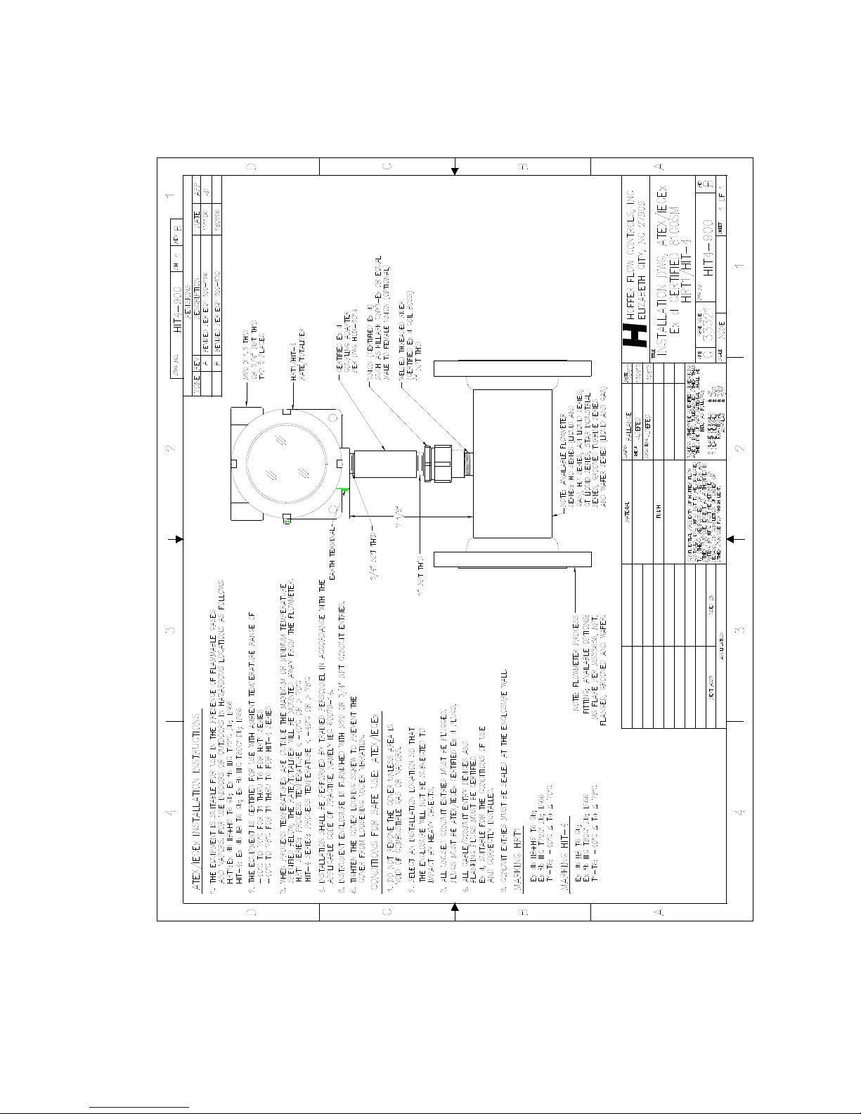
60 Appendix B – Installation Drawings and Conditions
for Safe Use for Certified Systems
HP-327 HIT-4U
Flow-Tech, Inc. | In MD 410-666-3200 - In VA 804-752-3450 | www.flowtechonline.com
Page 66
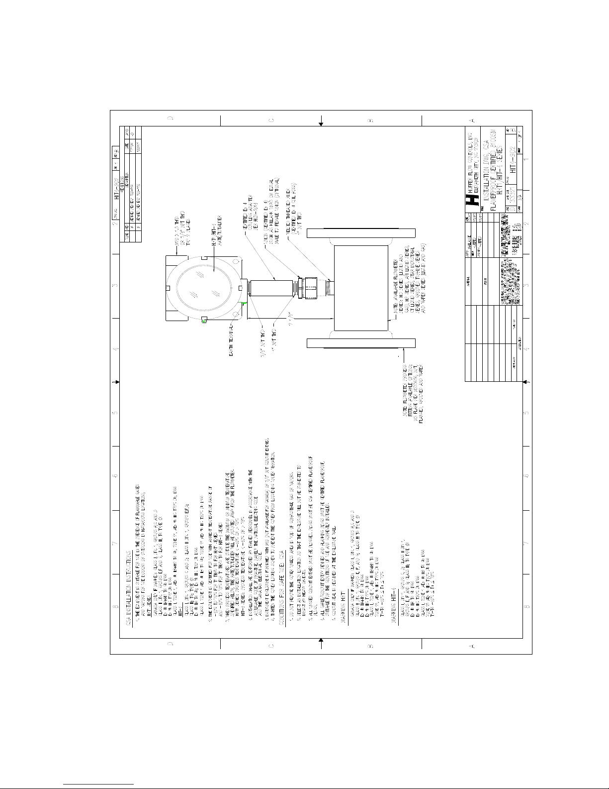
Appendix B – Installation Drawings and Conditions 61
for Safe Use for Certified Systems
HIT-4U HP-327
Flow-Tech, Inc. | In MD 410-666-3200 - In VA 804-752-3450 | www.flowtechonline.com
Page 67
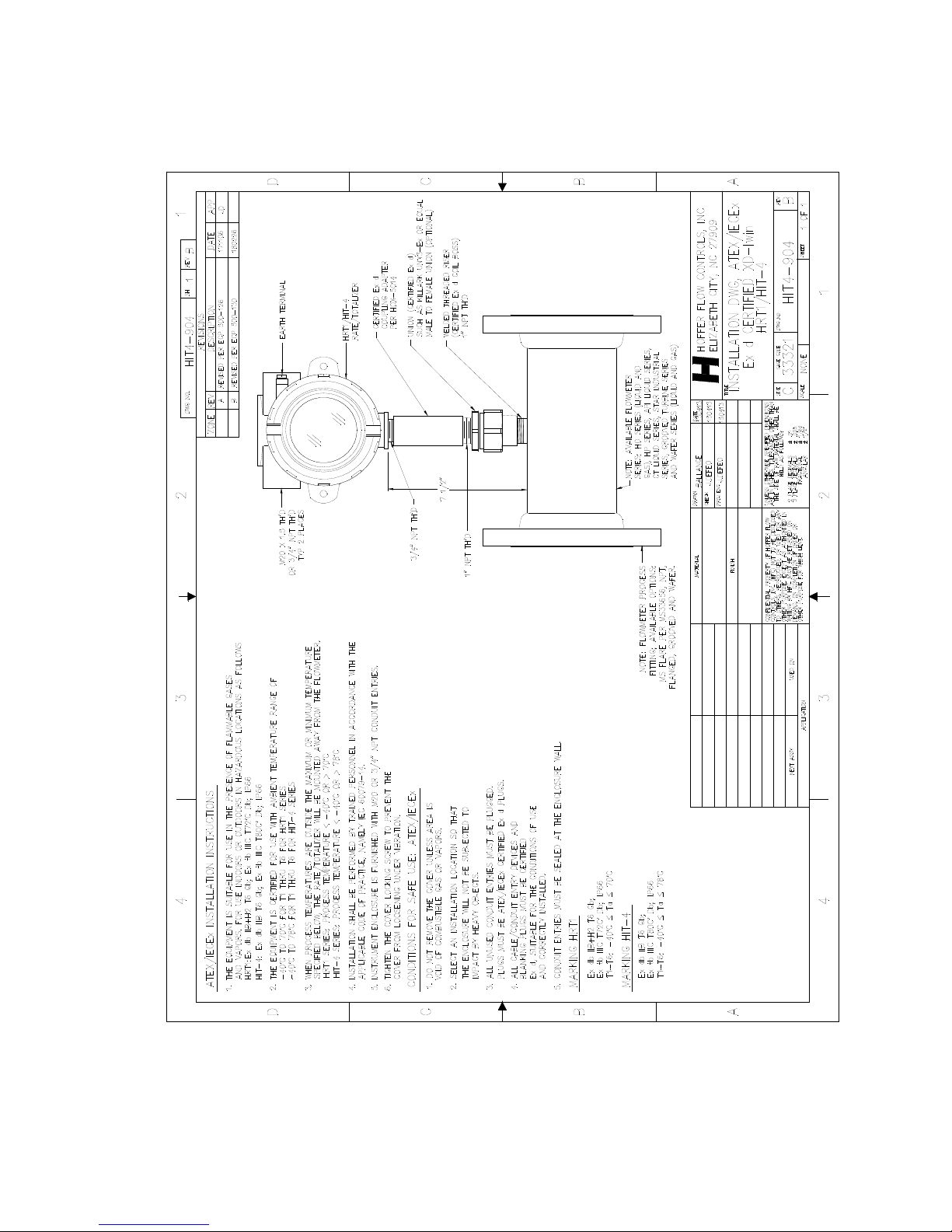
62 Appendix B – Installation Drawings and Conditions
for Safe Use for Certified Systems
HP-327 HIT-4U
Flow-Tech, Inc. | In MD 410-666-3200 - In VA 804-752-3450 | www.flowtechonline.com
Page 68
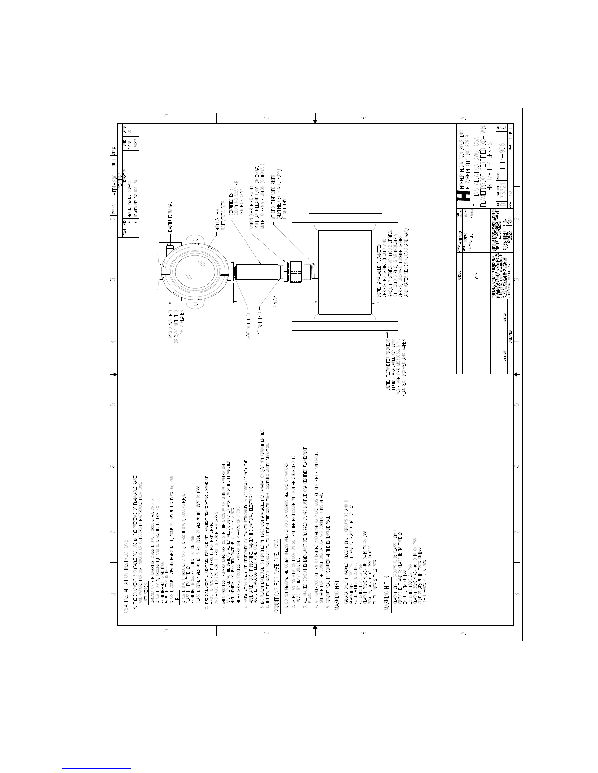
Appendix B – Installation Drawings and Conditions 63
for Safe Use for Certified Systems
HIT-4U HP-327
Flow-Tech, Inc. | In MD 410-666-3200 - In VA 804-752-3450 | www.flowtechonline.com
Page 69
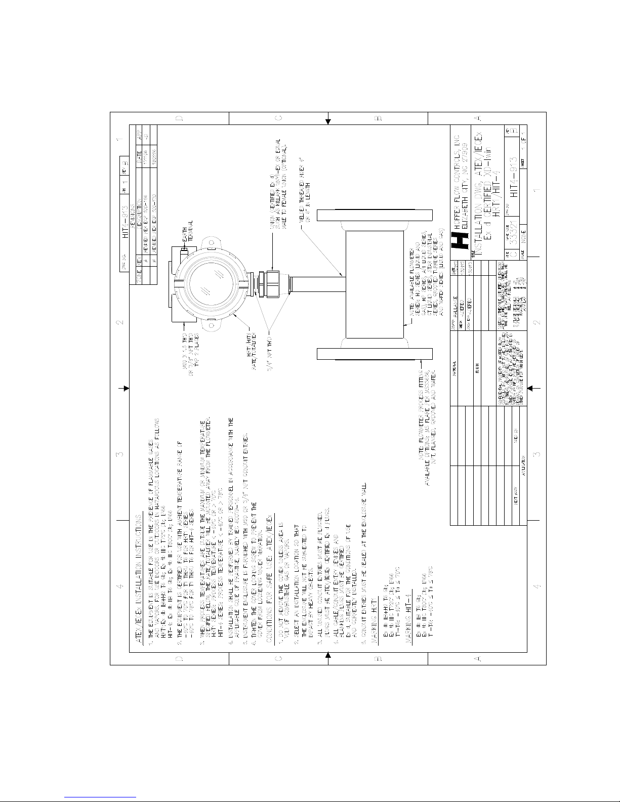
64 Appendix B – Installation Drawings and Conditions
for Safe Use for Certified Systems
HP-327 HIT-4U
Flow-Tech, Inc. | In MD 410-666-3200 - In VA 804-752-3450 | www.flowtechonline.com
Page 70
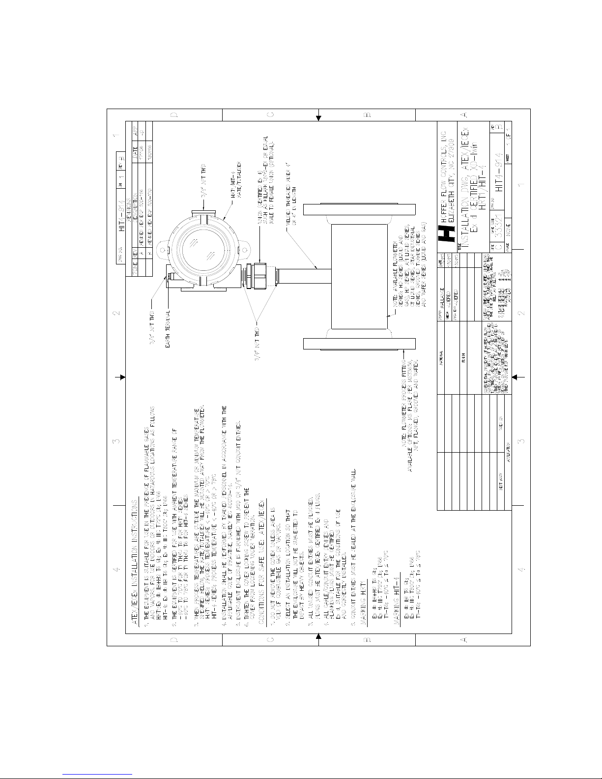
Appendix B – Installation Drawings and Conditions 65
for Safe Use for Certified Systems
HIT-4U HP-327
Flow-Tech, Inc. | In MD 410-666-3200 - In VA 804-752-3450 | www.flowtechonline.com
Page 71
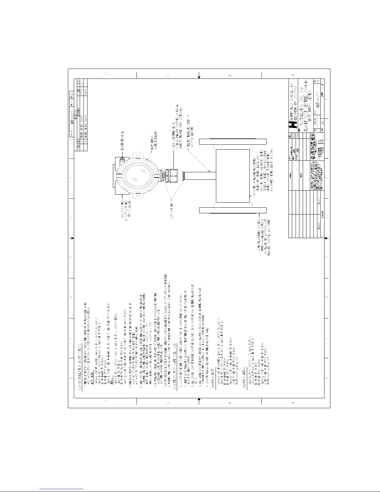
66 Appendix B – Installation Drawings and Conditions
for Safe Use for Certified Systems
HP-327 HIT-4U
Flow-Tech, Inc. | In MD 410-666-3200 - In VA 804-752-3450 | www.flowtechonline.com
Page 72
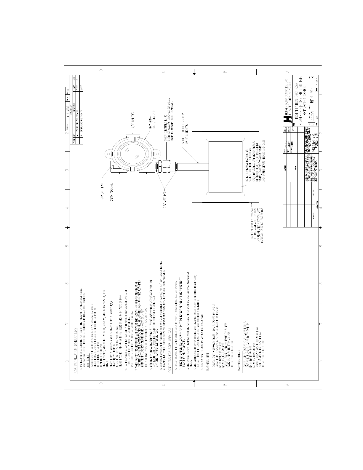
Appendix B – Installation Drawings and Conditions 67
for Safe Use for Certified Systems
HIT-4U HP-327
Flow-Tech, Inc. | In MD 410-666-3200 - In VA 804-752-3450 | www.flowtechonline.com
Page 73
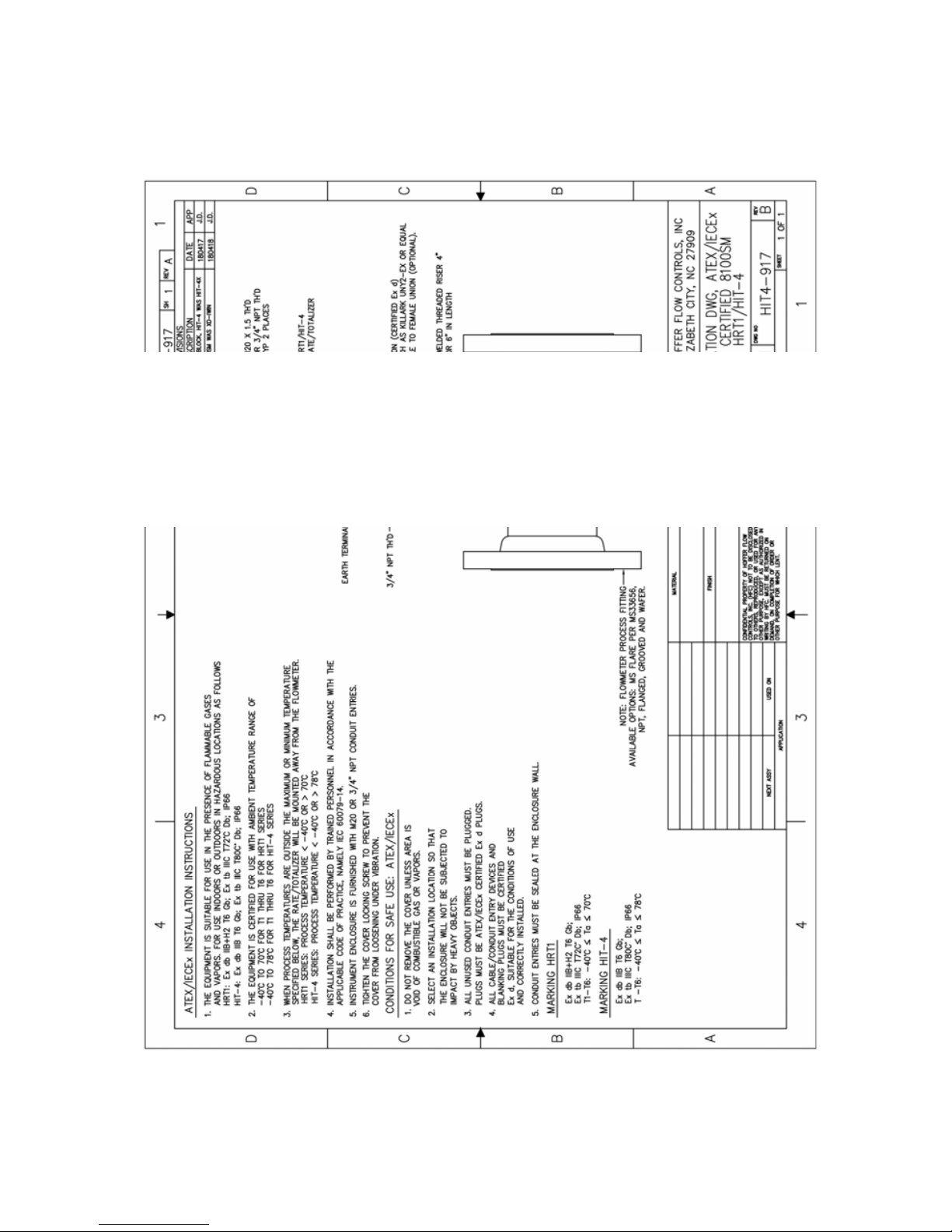
68 Appendix B – Installation Drawings and Conditions
for Safe Use for Certified Systems
HP-327 HIT-4U
Flow-Tech, Inc. | In MD 410-666-3200 - In VA 804-752-3450 | www.flowtechonline.com
Page 74
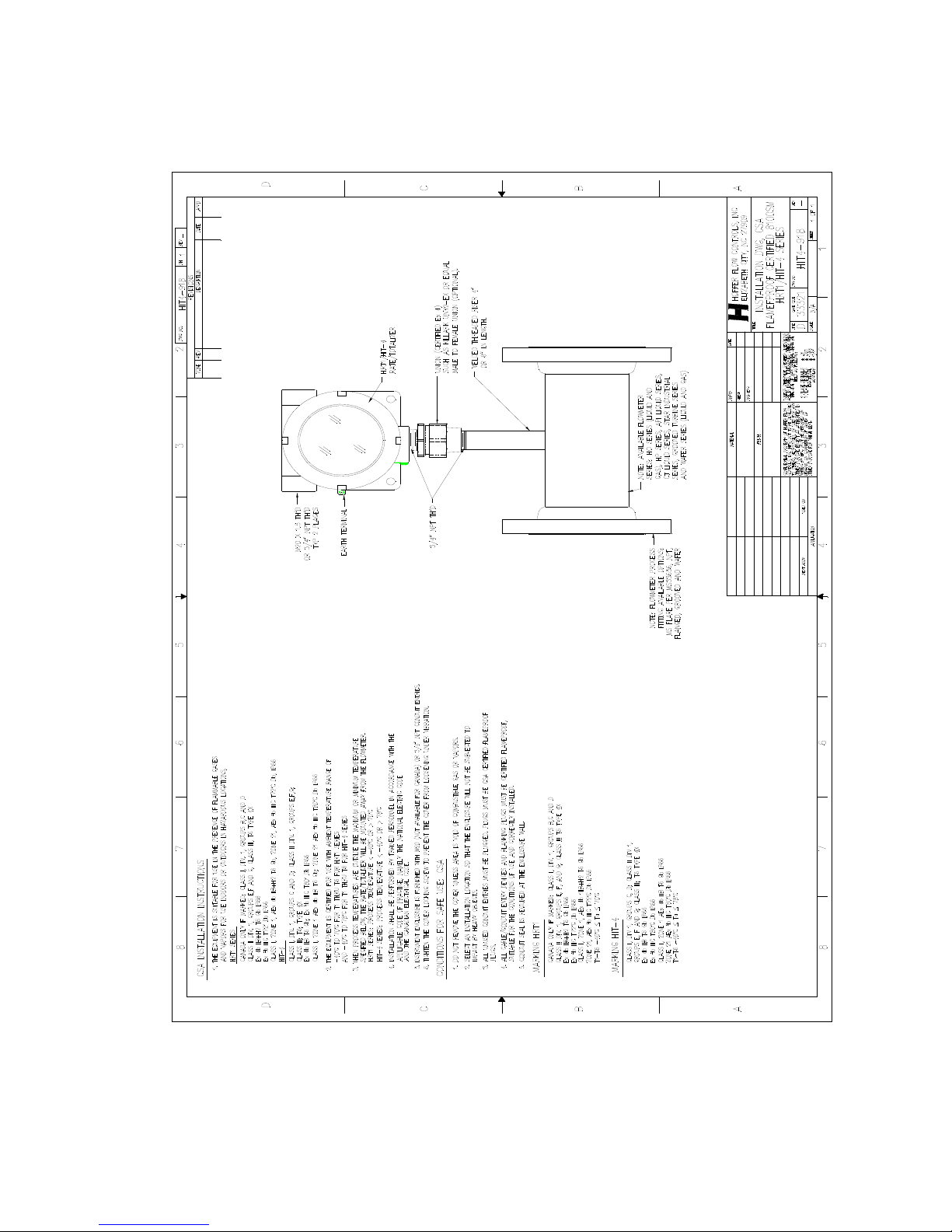
Appendix B – Installation Drawings and Conditions 69
for Safe Use for Certified Systems
HIT-4U HP-327
Flow-Tech, Inc. | In MD 410-666-3200 - In VA 804-752-3450 | www.flowtechonline.com
Page 75
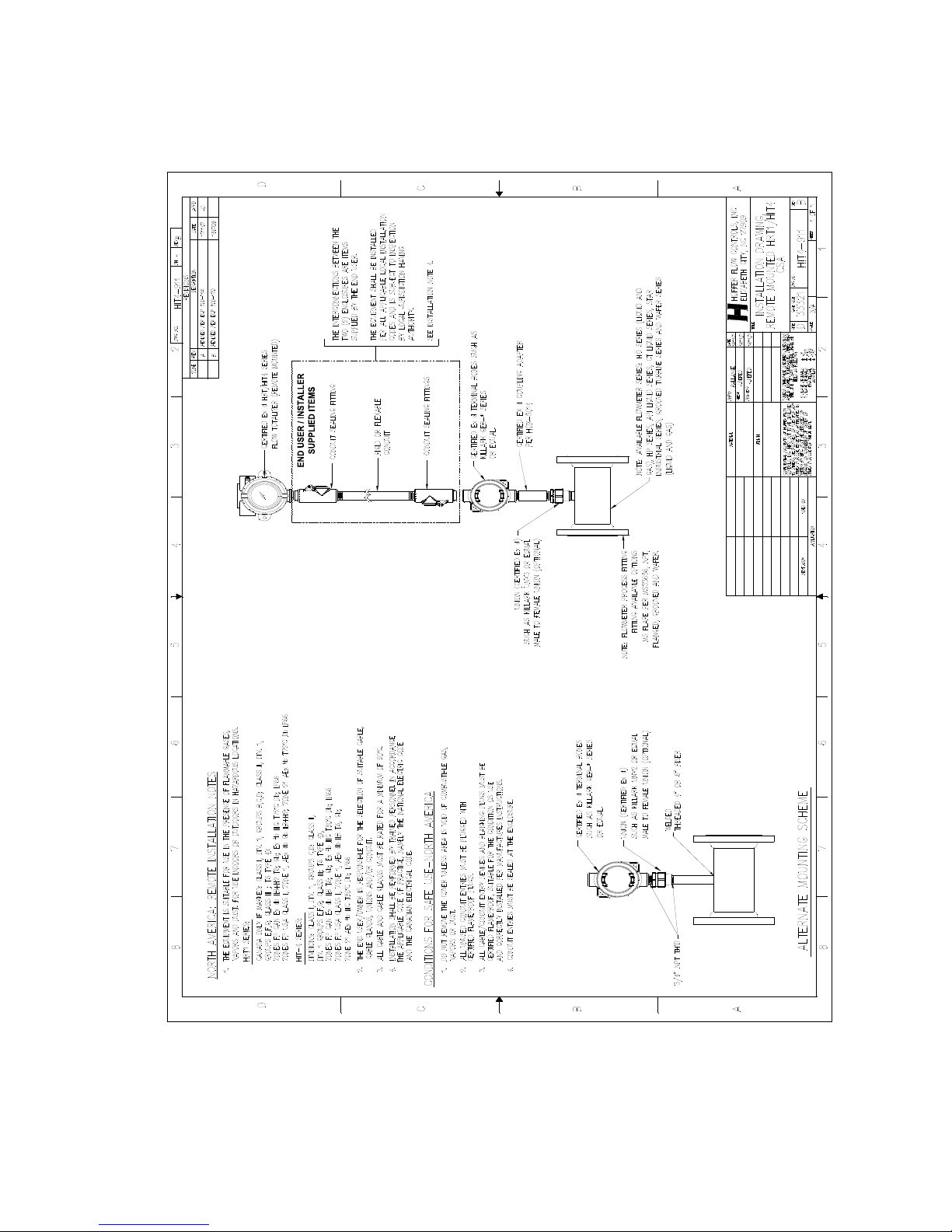
70 Appendix B – Installation Drawings and Conditions
for Safe Use for Certified Systems
HP-327 HIT-4U
Flow-Tech, Inc. | In MD 410-666-3200 - In VA 804-752-3450 | www.flowtechonline.com
Page 76
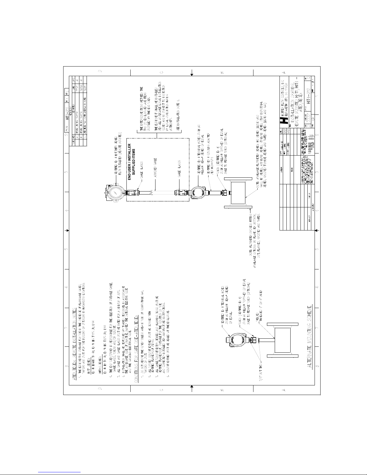
Appendix B – Installation Drawings and Conditions 71
for Safe Use for Certified Systems
HIT-4U HP-327
Flow-Tech, Inc. | In MD 410-666-3200 - In VA 804-752-3450 | www.flowtechonline.com
 Loading...