

Page 1

107 Kitty Hawk Lane, P.O. Box 2145, Elizabeth City, NC 27906-2145
800-628-4584 252-331-1997 FAX 252-331-2886
www.hofferflow.com E-mail: info@hofferf low.com
Model: CAT3
DC or AC Powered Microprocessor
Controlled Transmitter
USER’S MANUAL
April 2009
HP-312
July 2019
107 Kitty Hawk Lane ● P.O. Box 2145 ● Elizabeth City, NC 27909
1-800-628-4584 ● (252) 331-1997 ● Fax (252) 331-2886
www.hofferflow.com email: [email protected]
Page 2

Page 3

NOTICE
HOFFER FLOW CONTROLS, INC. makes no warranty of any kind with regard to
this material, including, but not limited to, the implied warranties of merchantability
and fitness for a particular purpose.
This manual has been provided as an aid in installing, connecting, calibrating, operating,
and servicing this unit. Every precaution for accuracy has been taken in the
preparation of this manual; however, HOFFER FLOW CONTROLS, INC. neither
assumes responsibility for any omissions or errors that may appear nor assumes
liability for any damages that may result from the use of the products in accordance
with information contained in the manual.
HOFFER FLOW CONTROLS' policy is to provide a user manual for each item
supplied. Therefore, all applicable user manuals should be examined before
attempting to install or otherwise connect a number of related subsystems.
During installation, care must be taken to select the correct interconnecting wiring
drawing. The choice of an incorrect connection drawing may result in damage to the
system and/or one of the components.
Please review the complete model number of each item to be connected and locate the
appropriate manual(s) and/or drawing(s). Identify all model numbers exactly before
making any connections. A number of options and accessories may be added to the
main instrument, which are not shown on the basic user wiring. Consult the appropriate
option or accessory user manual before connecting it to the system. In many cases, a
system wiring drawing is available and may be requested from HOFFER FLOW
CONTROLS.
This document contains proprietary information, which is protected by copyright.
All rights are reserved. No part of this document may be photocopied, reproduced,
or translated to another language without the prior written consent of HOFFER
FLOW CONTROLS, INC.
HOFFER FLOW CONTROLS’ policy is to make running changes, not model
changes, whenever an improvement is possible. This affords our customers the
latest in technology and engineering. The information contained in this document is
subject to change without notice.
Return Requests / Inquiries
Direct all warranty and repair requests/inquiries to the Hoffer Flow Controls
Customer Service Department, telephone number (252) 331-1997 or 1-800-628-
4584. BEFORE RETURNING ANY PRODUCT(S) TO HOFFER FLOW
CONTROLS, PURCHASER MUST OBTAIN A RETURNED MATERIAL
AUTHORIZATION (RMA) NUMBER FROM HOFFER FLOW CONTROLS’
CUSTOMER SERVICE DEPARTMENT (IN ORDER TO AVOID PROCESSING
DELAYS). The assigned RMA number should then be marked on the outside of the
return package and on any correspondence.
FOR WARRANTY RETURNS, please
have the following information available
BEFORE contacting HOFFER FLOW
CONTROLS:
1. P.O. number under which the product
was PURCHASED,
2. Model and serial number of the
product under warranty, and
3. Repair instructions and/or specific
problems relative to the product.
FOR NON-WARRANTY
CALIBRATIONS, consult HOFFER FLOW
CONTROLS for current repair/ calibration
charges. Have the following information
available BEFORE contacting HOFFER
FLOW CONTROLS:
1. P.O. number to cover the COST of the
repair/calibration,
2. Model and serial number of the product
and
3. Repair instructions and/or specific
problems relative to the product.
REPAIRS OR
HFC 9708
Page 4

Limited Warranty
HOFFER FLOW CONTROLS, INC. ("HFC") warrants HFC's products
("goods") described in the specifications incorporated in this manual to be free
from defects in material and workmanship under normal use and service, but
only if such goods have been properly selected for the service intended,
properly installed and properly operated and maintained. This warranty shall
extend for a period of one (1) year from the date of delivery to the original
purchaser (or eighteen (18) months if the delivery to the original purchaser
occurred outside the continental United States). This warranty is extended only
to the original purchaser ("Purchaser"). Purchaser's sole and exclusive remedy
is the repair and/or replacement of nonconforming goods as provided in the
following paragraphs.
In the event Purchaser believes the goods are defective, the goods must be
returned to HFC, transportation prepaid by Purchaser, within twelve (12)
months after delivery of goods (or eighteen (18) months for goods delivered
outside he continental United States) for inspection by HFC. If HFC's
inspection determines that the workmanship or materials are defective, the
goods will be either repaired or replaced, at HFC's sole determination, free of
additional charge, and the goods will be returned, transportation paid by HFC,
using he lowest cost transportation available.
Prior to returning the goods to HFC, Purchaser must obtain a Returned Material
Authorization (RMA) Number from HFC's Customer Service Department
within 30 days after discovery of a purported breach of warranty, but no later
than the warranty period; otherwise, such claims shall be deemed waived. See
the Return Requests/Inquiries Section of this manual.
If HFC's inspection reveals the goods are free of defects in material and
workmanship or such inspection reveals the goods were improperly used,
improperly installed, and/or improperly selected for service intended, HFC will
notify the purchaser in writing and will deliver the goods back to Purchaser
upon (i) receipt of Purchaser's written instructions and (ii) the cost of
transportation. If Purchaser does not respond within thirty (30) days after notice
from HFC, the goods will be disposed of in HFC's discretion.
HFC does not warrant these goods to meet the requirements of any safety code
of any state, municipality, or other jurisdiction, and Purchaser assumes all risk
and liability whatsoever resulting from the use thereof, whether used singly or
in combination with other machines or apparatus.
This warranty shall not apply to any HFC goods or parts thereof, which have
been repaired outside HFC's factory or altered in any way, or have been subject
to misuse, negligence, or accident, or have not been operated in accordance
with HFC's printed instructions or have been operated under conditions more
severe than, or otherwise exceeding, those set forth in the specifications for
such goods.
THIS WARRANTY IS EXPRESSLY IN LIEU OF ALL OTHER WARRANTIES,
EXPRESSED OR IMPLIED, INCLUDING ANY IMPLIED WARRANTY OF
MERCHANTABILITY OR FITNESS FOR A PARTICULAR PURPOSE. HFC
SHALL NOT BE LIABLE FOR ANY LOSS OR DAMAGE RESULTING
INDIRECTLY
THE GENERALITY OF THE FOREGOING
THE
DAMAGES FOR WHICH THE
DAMAGES TO PROPERTY
NEITHER ASSUMES NOR AUTHORIZES ANY PERSON TO ASSUME FOR IT ANY OTHER
LIABILITY IN CONNECTION WITH THE SALE OR USE OF
ARE NO ORAL AGREEMENTS OR WARRANTIES COLLATERAL TO OR AFFECTING THE
AGREEMENT
REPLACEMENT OF NONCONFORMING GOODS AS PROVIDED IN THE PRECEDING
PARAGRAPHS
INCLUDING INDIRECT
, FROM THE USE OR LOSS OF USE OF THE GOODS. WITHOUT LIMITING
PURCHASER'S EXPENSES FOR DOWNTIME OR FOR MAKING UP DOWNTIME,
, THIS EXCLUSION FROM LIABILITY EMBRACES
PURCHASER MAY BE LIABLE TO OTHER PERSONS,
, AND INJURY TO OR DEATH OF ANY PERSONS. HFC
HFC'S GOODS, AND THERE
. PURCHASER'S SOLE AND EXCLUSIVE REMEDY IS THE REPAIR AND/OR
. HFC SHALL NOT BE LIABLE FOR ANY OTHER DAMAGES WHATSOEVER
, INCIDENTAL, OR CONSEQUENTIAL DAMAGES.
, DIRECTLY OR
HFC 9708
Page 5

CONTENTS
1. Introduction----------------------------------------------------------------- 1
1.1 Model Number Designation --------------------------------------- 3
2. Specifications --------------------------------------------------------------- 7
3. Installation and Operation----------------------------------------------- 9
3.1 Power Supply-------------------------------------------------------- 9
3.2 Flowmeter Input---------------------------------------------------- 10
3.3 Pulse Output --------------------------------------------------------12
3.4 Analog Output------------------------------------------------------14
3.5 Alarm Outputs------------------------------------------------------16
3.6 Communications Port --------------------------------------------- 18
3.7 Wiring ---------------------------------------------------------------19
APPENDIX A - Default Configuration------------------------------------20
APPENDIX B - Declaration--------------------------------------------------22
APPENDIX C - Installation and Conditions for Safe Use Drawings
for Certified Systems ----------------------------------------------------------24
HP-312 CAT3
Page 6

CAT3 HP-312
Page 7

I n t r o d uc t io n 1
H
P
A
P
C
P
P
A
O
P
LOWA
C
L
I
C
1. Introduction
The CAT3 is a versatile DC or AC powered microprocessor-based
transmitter, which provides pulse output, analog output and High/Low
flow alarm options. Up to 3 circuit boards may be installed to provide
a variety of input/output options.
The flowmeter input circuitry will accept a variety of signal types
including, low level sinusoidal, MCP/RF, pulse and contact closure.
Optional 20-point linearization is available to correct for flowmeter
non-linearities, improving overall system accuracy. The CAT3 is
compatible with all Hoffer turbine flowmeters as well as the H.O.G.
series positive displacement flowmeters.
CAT3 Block Diagram
PULSE OUT
ANALOG OUT
FLOWMETER INPUT
CA182
C/DC
ONVERTER
REAMP
CA180
R
ONDITIONED SIGNAL
ULSE OUT
NALOG OUT
CA184
HIGH
ALARM
LARM
MICROCONTROLLER
OM
DAC
NTERFACE
PCA183
RS232
IGH ALARM OUT
OW ALARM OUT
An RS232 communications port located under the top plate allows
CAT3 to be remotely configured using DevConfig 3.0, a PC
application program that is included with all units.
CAT3 HP-312
Page 8

2 Introduction
The standard unit is packaged in an extruded aluminum enclosure for
wall mounting or may be mounted directly on a flowmeter using an
optional NEMA 4X or EX enclosure. An optional bracket is also
available for mounting on standard DIN rail.
HP-312 CAT3
Page 9

I n t r o d uc t io n 3
1.1 Model Number Designation
MODEL CAT3-( A )-( B )-( C )-( D )-( E )-( F )-( G)
PULSE INPUT
LINEARIZED PULSE OUTPUT
LINEARIZED ANALOG OUTPUT
POWER SUPPLY
ALARM OUTPUT
ENCLOSURE STYLE
SPECIAL FEATURES
PULSE INPUT
MODEL CAT3-( A
( A )
OPTION
(1) MAG COIL, PULSE, DRY CONTACT
(2) MC3P
(3) ISOLATED PULSE, RPM, RPR AND HALL EFFECT COILS
LINEARIZED PULSE OUTPUT
MODEL CAT3-( )-( B )-( )-( )-( )-( )-( )
( B )
OPTION
(1) 0-5 TTL / CMOS
(2) OPEN COLLECTOR
(3) OPEN COLLECTOR WITH PULL UP TO V+
(4) AC SQUARE WAVE
(5) 0-10V SQUARE WAVE
NOTE: NOT RECOMMENDED FOR USE AS A FLOW RATE SIGNAL.
MAXIMUM INPUT SENSOR FREQUENCY ALLOWED IS 100HZ.
LINEARIZED ANALOG OUTPUT
MODEL CAT3-(
( C )
OPTION
(1) 4-20 MA
(5) 1-5 VDC
POWER SUPPLY
MODEL CAT3-(
( D )
OPTION
(DC) 13-30 VDC
(AC) 100-240 VAC
NOTE: WHEN (AC) IS SELECTED, THE ALARM OPTION IS NOT AVAILABLE.
USE REMOTE ACC39B POWER SUPPLY IF REQUIRED.
)-( )-( )-( )-( )-( )-( )
)-( )-( C )-( )-( )-( )-( )
)-( )-( )-( D )-( )-( )-( )
CAT3 HP-312
Page 10

4 Introduction
ALARM OUTPUT
MODEL CAT3-(
OPTION
( E )
(4) HIGH OPEN COLLECTOR
(5) HIGH TTL / CMOS
(6) HIGH RELAY ONE SPDT, CONTACT RATED @ 2A 30V
(7) LOW OPEN COLLECTOR
(8) LOW TTL / CMOS
(9) LOW RELAY ONE SPDT, CONTACT RATED @ 2A 30V
NOTE: WHEN ALARM OPTION IS SELECTED, (AC) POWER IS NOT AVAILABLE.
USE REMOTE ACC39B POWER SUPPLY.
ENCLOSURE STYLE
MODEL CAT3-(
OPTIONS
(1) GENERAL PURPOSE.
2.6"L X 2.6"H X 2.6"W MINIMUM MOUNTING SPACE.
(D) 2" LONG DIN RAIL MOUNT SINGLE UNIT.
UP TO 20 CAT3 UNITS CAN BE MOUNTED ON A SINGLE
RAIL. ADD 2" PER UNIT.
(E3) EXPLOSION-PROOF (ALL CONDUIT PORTS ARE ¾” FNPT)
(E3M) EXPLOSION-PROOF (CONDUIT PORTS D2 & D3 = M20 THR’D;
(E4)* EXPLOSION-PROOF - FOR USE WITH AC POWERED CAT ONLY
(E6) EXPLOSION-PROOF STAINLESS STEEL
(ALL CONDUIT PORTS ARE ¾"FNPT)
(E6M) EXPLOSION-PROOF STAINLESS STEEL
( F )
(NOT Ex d SYSTEM CERTIFIED)
*FOR Ex d CERTIFIED SYSTEM USE E6 OR E6M ENCLOSURE
)-( )-( )-( )-( E )-( )-( )
)-( )-( )-( )-( )-( F )-( )
(M20 NOT AVAILABLE FOR CANADA)
NOTE: FOR UL LISTED EXPLOSION-PROOF APPLICATIONS CONTACT FACTORY
.
HP-312 CAT3
Page 11

I n t r o d uc t io n 5
SPECIAL FEATURES
MODEL CAT3-(
OPTIONS
( G )
(CE) MARK REQUIRED FOR EUROPE
(SP) ANY SPECIAL FEATURES THAT ARE NOT COVERED IN THE
MODEL NUMBER, USE A WRITTEN DESCRIPTION OF THE -SP
(MIL) DESIGNED TO MEET EMC STDS EN5011-1992 AND EN61326-1:1997
(CFX) 6.75" LONG RISER AND UNION FOR EXPLOSION-PROOF SYSTEM
CERTIFIED ENCLOSURES
“X” RISER TURBINE OPTION AND (EXP) OR (EX) SPECIAL
FEATURES OPTION UNDER FLOWMETERSAS FOLLOWS:
(EXP) FOR CANADIAN INSTALLATION OR
(EX) FOR NON-CANADIAN INSTALLATION.
(C) REMOTED MOUNTED FOR EXPLOSION-PROOF SYSTEM
CERTIFIED ENCLOSURE
SPECIAL FEATURES UNDER FLOWMETERS AS FOLLOWS:
(EXP) FOR CANADIAN INSTALLATION OR
(EX) FOR NON-CANADIAN INSTALLATION.
(X) NO SPECIAL FEATURES
STYLE E3, E3M, E6 AND E6M SYSTEM CERTIFIED RATINGS
- CSA/FM: CLASS I, DIV. 1, GR. BCD; CLASS II, DIV. 1, GR. EFG;
CLASS III, TYPE 4X,
CLASS 1 ZONE 1 AEx db IIB + H2 T6/T5 Gb,
Ex d IIB+H2 T6/T5; Gb; Ex tb T80°C/T86°C IIIC Db; IP66
CLASS I, ZONE 21 AEx tb T80°C/T86°C IIIC Db; IP 66
- ATEX/IECEx: II 2 G Ex db IIB + H2, T6/T5 Gb
II 2 D Ex tb IIIC T80°C/T86°C Db; IP66
T6: -40°C ≤ Ta ≤ 79°C; T5: -40°C ≤ Ta ≤ 85°C
NOTES: 1. IF ENCLOSURE IS MOUNTED ON TURBINE FLOWMETER,
RISER MUST BE SPECIFIED ON METER.
2. PULSE SCALING IS SUPPLIED AS A STANDARD IN THE BASE
PRISE AND IS SCALED TO THE UNIT MEASURE.
3. WINDOWS® BASED SETUP AND CABLE KIT CONSISTS OF:
1 EA. HIT2A-301
1EA. CABLE MODEL 26886
CAT3 HP-312
)-( )-( )-( )-( )-( )-( G )
MOUNTED ON TURBINE. USED WITH
NOTE: IF PROCESS TEMP IS < -40°C AND > 79°C, EX-PROOF
ENCLOSURE MUST BE MOUNTED REMOTELY.
. FOR USE WITH (C-EXP) OR (EX)
NOTE: “X” RISER, CERTIFIED UNION, REDUCER AND ENCLOSURE
(TO BE SPECIFIED) MOUNTED ON FLOWMETER
Page 12

6 Introduction
This page intentionally left blank.
HP-312 CAT3
Page 13

Specifications 7
2. Specifications
General Specifications
Input Signal Type: Magnetic pick up, MCP pick up,
Contact Closure, Pulse
Input Frequency Range: 0.2 Hz to 4 KHz
Signal Level: 10 mV rms to 30 Vdc
Power Supply: 13-30 Vdc (Reverse polarity protected)
100-240 Vac (Fuse rating 0.5A, 250 Vac)
Analog Output: 4-20mA, 1-5V
Analog Output
Response Time: 1/8 sec.*
Load Resistance: Max 650 Ohms at 24 Vdc
Accuracy: +/- 0.02% of full scale @ 20 C
Temperature Drift: 40ppm/deg C
Pulse Output: 0-5, 0-10V, Open Collector, AC square
Internal pull-up resistor 2.7k Ohms
Recommended load min. 50k Ohms
Maximum Pulse 1, 2, 4, 8, 100, 50% Duty Cycle
Frequency:
Pulse Scaling: Per flow unit of measure, divide by 1, 10, 100
Hi/Lo Alarm: Relay (2A, 30 Vdc), 0-5V, Open Collector
(0.5A, 30 Vdc)
Communications: RS232 port for Configuration and diagnostics
o
Operating Temperature: T5 and STD: -40
T6: -40
Humidity: 0-90% Non-condensing
Enclosure: Extruded aluminum
DIN rail mount
Explosion Proof
Regulatory: CE compliant
*Limited by signal frequency and MST settings. Refer to Section 3.4.
Options
20 Point Linearization
o
≤ Ta ≤ 79o C
≤ Ta ≤ 85o C
CAT3 HP-312
Page 14

8 Specifications
This page intentionally left blank.
HP-312 CAT3
Page 15
Installation and Operation 9
3. Installation and Operation
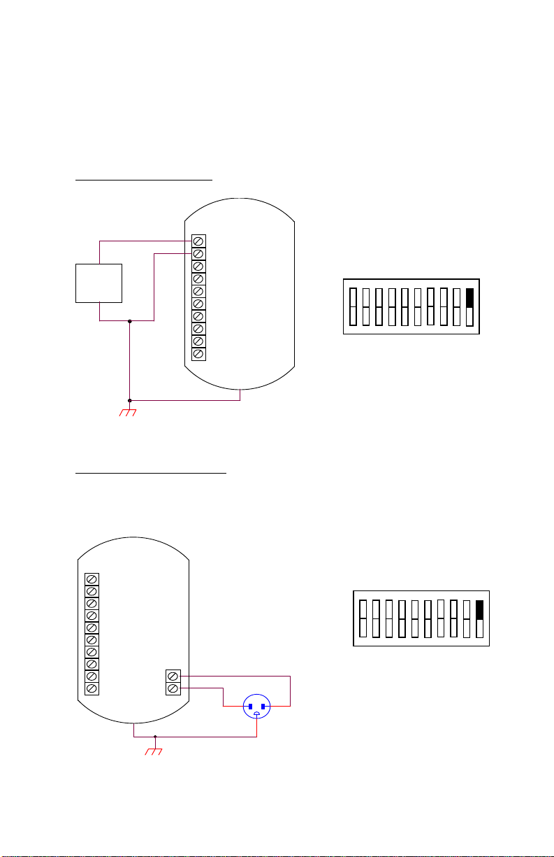
3.1 Power Supply
DC Power (13-30 VDC)
DC+
+
DC
POWER
SUPPLY
-
AC Power (100-240 VAC)
AC power for CAT3 requires an optional circuit board, PCA182. The Alarm
option (PCA184) is not available when the AC Power option is equipped.
DCSIG+
SIGANLG
PULSE+
PULSEN/C
N/C
N/C
1
PCA180
SW2
DC+
DCSIG+
SIGANLG
PULSE+
PULSEN/C
N/C
N/C
L1
L2
PLUG AC MALE
NEUTRAL HOT
1
PCA180
SW2
CAT3 HP-312
Page 16
10 Installation and Operation
3.2 Flowmeter Input
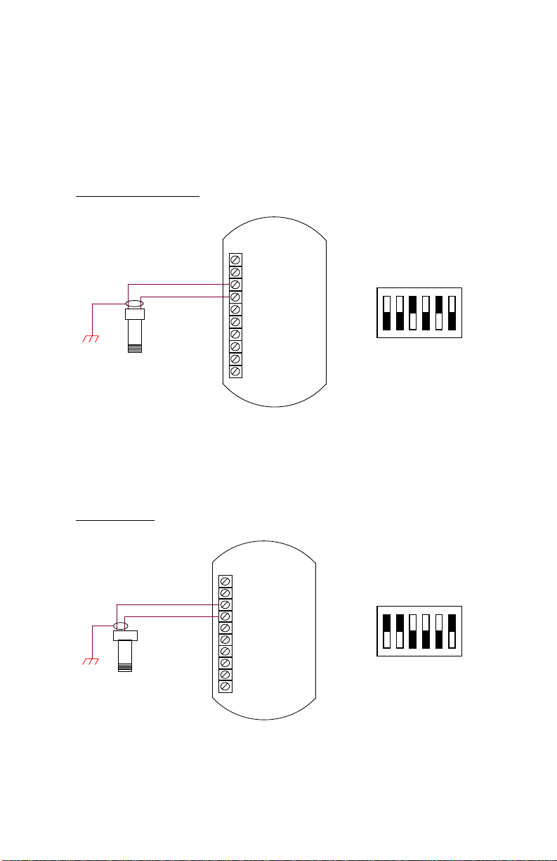
The Preamp circuitry for conditioning the flow signal is located on PCA180.
The following drawings illustrate typical connections and switch settings on
PCA180 for various input signals.
Magnetic Pickup Coil
DC+
DC-
SIG+
A B
Mag Pickup Coil
SIGANLG
PULSE+
PULSEN/C
N/C
N/C
1
PCA180
SW1
MCP/RF Coil
A B
C
Modulated Carrier Pickup (RF)
DC+
DCSIG+
SIGANLG
PULSE+
PULSEN/C
N/C
N/C
1
PCA180
SW1
HP-312 CAT3
Page 17
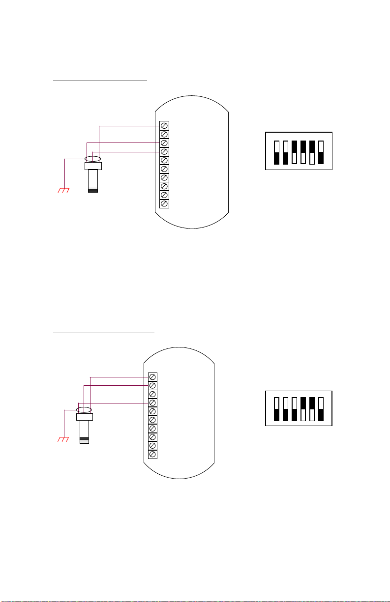
Redi-Pulse (TTL Pulse)
BA
C
Redi-Pulse (TTL) Pickup Coil
Redi-Pulse (Open Collector)
Installation and Operation 11
DC+
DCSIG+
SIGANLG
PULSE+
PULSEN/C
N/C
N/C
1
PCA180
SW1
DC+
DC-
SIG+
AB
C
Redi-Pulse (Open Collector)
Pickup Coil
SIGANLG
PULSE+
PULSEN/C
N/C
N/C
1
PCA180
SW1
CAT3 HP-312
Page 18
12 Installation and Operation
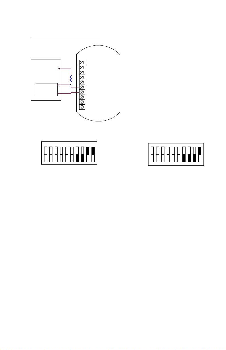
3.3 Pulse Output
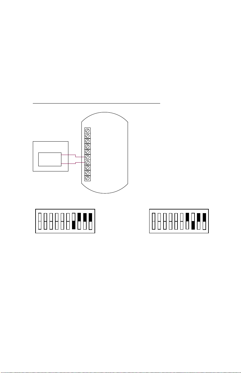
CAT3 provides a Pulse Output option that is scaled per flow unit of
measure by a factor of 1, 10 or 100. Pulse output frequency varies with
flow rate. The maximum frequency can be set at 1, 2, 4, 8, 100 Hz.
The following drawings illustrate typical connections and switch
settings for various pulse output options.
TTL(0-5V), 0-10V, High Level (DC In), AC Square
DC+
DC-
SIG+
USER DCS
PULSE
INPUT
+
-
SIGANLG
PULSE+
PULSEN/C
N/C
N/C
1
TTL(0-5V), 0-10V, AC Square
PCA180
SW2
1
PCA180
SW2
High Level Pulse, AC Square
HP-312 CAT3
Page 19
Installation and Operation 13
Open Collector, Isolated Pulse
USER DCS
PULSE
INPUT
V+
2.7K
+
-
DC+
DCSIG+
SIGANLG
PULSE+
PULSEN/C
N/C
N/C
1
PCA180
SW2
Open Collector
1
PCA180
SW2
Isolated Pulse
CAT3 HP-312
Page 20
14 Installation and Operation
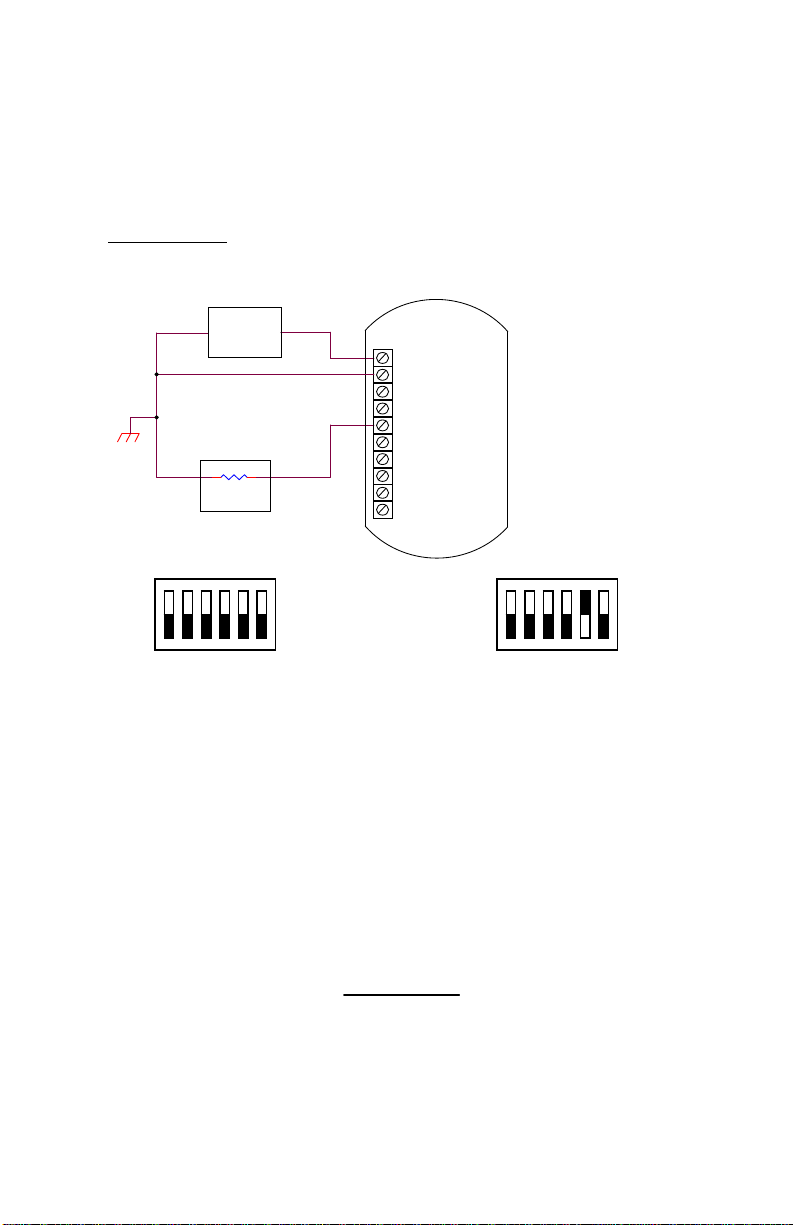
3.4 Analog Output
CAT3 provides an Analog Output option that will output an analog
current or voltage that is proportional to the flow rate.
Analog Output
DC
POWER
SUPPLY
LOAD
+
DC+
DCSIG+
SIGANLG
PULSE+
+
PULSEN/C
N/C
N/C
1
4–20 mA Output
PCA183
SW1
1
PCA183
SW1
1-5 V Output
The Microcontroller, located on PCA183, accepts the squarewave output of the preamplifier and performs all of the
calculations that are required to control the Loop Driver. After
measuring the frequency of the square-wave, the Microcontroller
uses the following equations to compute the flow rate and current.
flowrate
frequency
FM
xCFx
60
Kfactor
HP-312 CAT3
Page 21

Installation and Operation 15
Where:
Kfactor = Is dependent on the Flow Calculation Method setting and
is either the Average K-Factor or the Linearized KFactor from the Frequency / K-Factor table.
FM = Is the Flow rate Units setting of 0, 1, or 2. Where “0” is
for Seconds, “1” is for Minutes, and “2” is for Hours.
CF = Is the Correction Factor setting.
mAxmAcurrent 164
flowrate
AF
Where:
AF = Is the 20 mA maximum Flow rate value.
If the calculated flowrate is greater than the AF setting, the
current will be set to 24mA to indicate an “Over-range” condition.
After calculating the current, the Microcontroller digitally sends
the current information to the Loop Driver. The loop driver,
located on PCA183, uses the digital information sent to it by the
Microcontroller to set the current of the loop. The Loop Driver
also supplies power to the Microcontroller.
The analog output response time to reach steady state due to a
change in the flow rate is approximately 1/8 of a second. When
flow stops, the time for the analog output to return to 4 mA will
be between .25 and 8 seconds, depending on the Maximum
Sample Time (MST) setting. MST is adjusted using the NB=
(DATA) command, where NB is a value between 1 and 80. The
default MST setting is NB= 1. Adjusting the MST is only
recommended for low flow applications where the minimum input
frequency is below 1 Hz.
CAT3 HP-312
Page 22
16 Installation and Operation
H
d
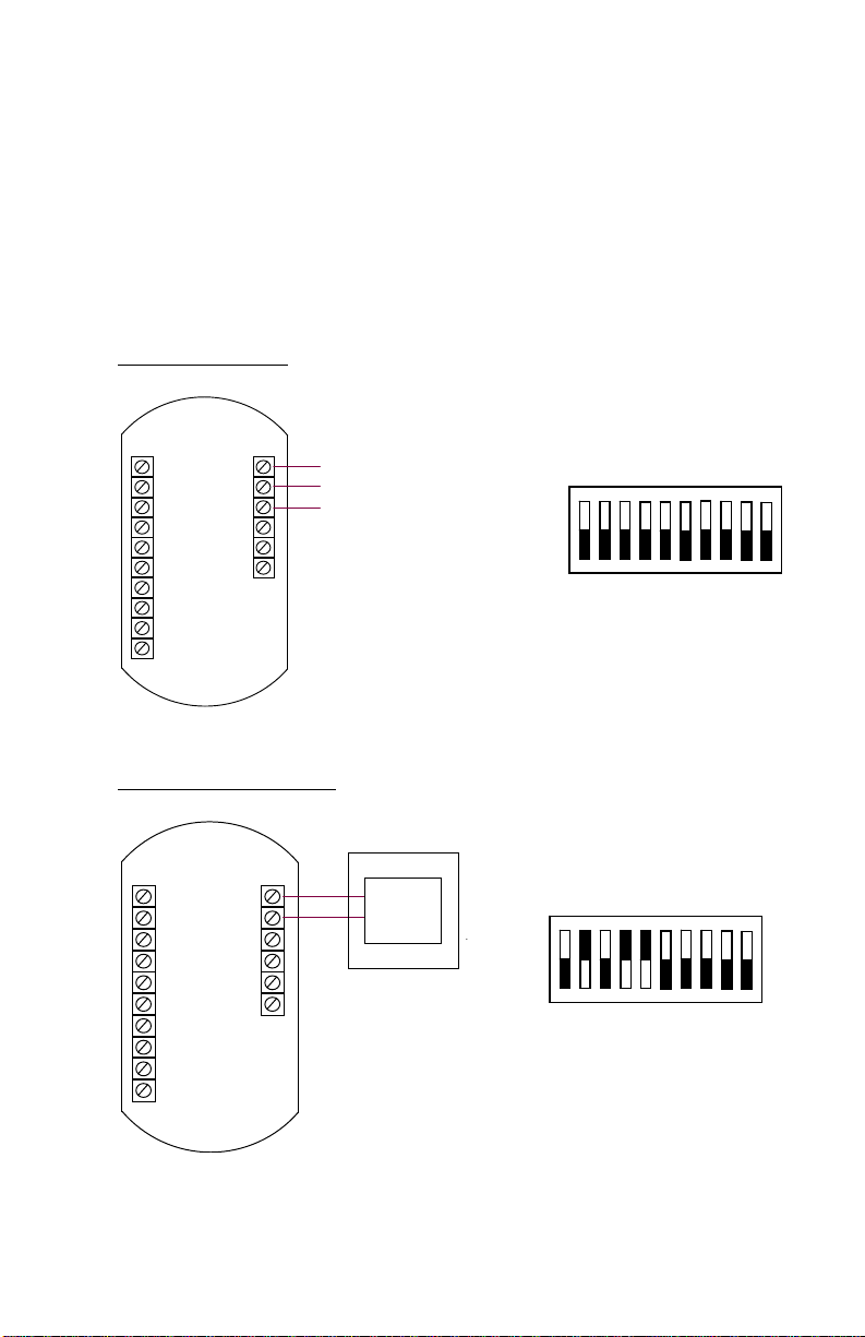
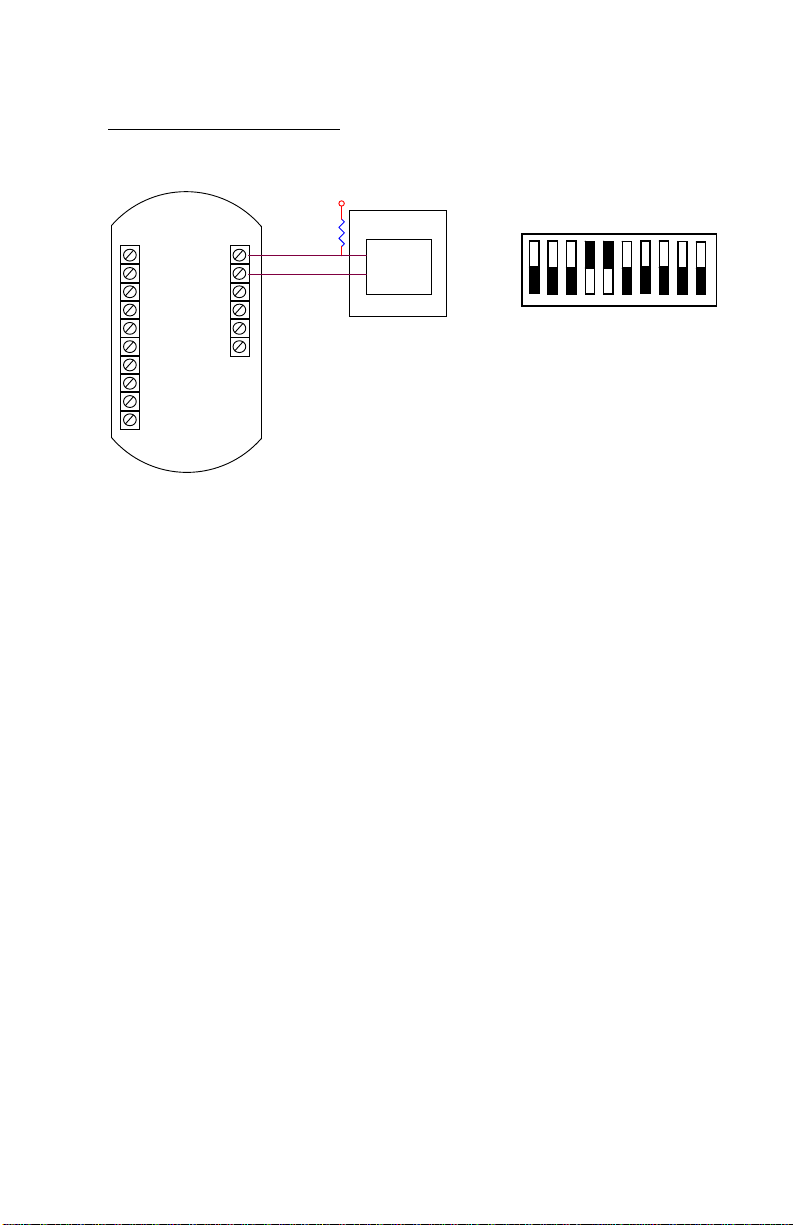
3.5 Alarm Outputs
CAT3 provides an optional High/Low Flow Alarm feature. Alarms
require an optional circuit board, PCA184. The Alarm option is not
available when the AC Power option is equipped. The drawings below
illustrate the typical connections and switch settings for various alarm
options.
Hi/Lo Alarm Relay
DC+
DC-
SIG+
SIGANLG
PULSE+
PULSEN/C
N/C
N/C
NC1
COM1
NO1
Hi/Lo Alarm TTL(0-5V)
DC+
ALARM1
DCSIG+
SIGANLG
PULSE+
PULSEN/C
N/C
N/C
COM
igh/Low-Nomally Close
High/Low-COM
High/Low-Nomally Open
USER DCS
+
Alarm
Indicator
-
1
1
PCA184
SW1
PCA184
SW1
HP-312 CAT3
Page 23
Installation and Operation 17
Hi/Lo Alarm Open Collector
DC+
DC-
SIG+
SIGANLG
PULSE+
PULSEN/C
N/C
N/C
ALARM1
COM
2.7K
V+
USER DCS
+
Indicator
-
Alarm
1
PCA184
SW1
CAT3 HP-312
Page 24
18 Installation and Operation
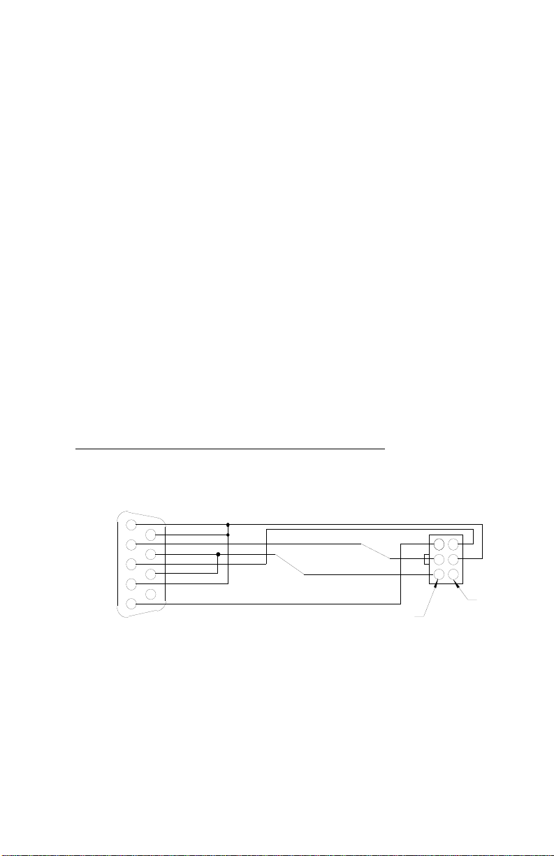
3.6 Communications Port
CAT3 is equipped with RS232 serial communication port for changing
CAT3 configuration, diagnostics functions, and flow monitoring.
Hoffer communication program DevConfig 3.0 must be used to
communicate with CAT3.
The RS232 serial port connector is located under the top plate of CAT3
and may be accessed by removing the two screws from the top plate. A
matching connector is provided with HOFFER HIT2A-301
Communications Cable. CAT3 unit has to be powered from external
supply in order to be able to communicate. Additional power for CAT3
communication circuitry is supplied by the RS232 serial port of the
computer/terminal. COM port settings must be set as follows:
Baud Rate: 2400
Data Bits: 8
Parity: None
Stop bits: 1
Handshaking: None
HOFFER HIT2A-301 Communications Cable
Molex
Pin 1
0511100660
or
Equivalent
Pin 2
CD 1
Rx 2
Tx 3
DTR 4
SIG COM 5
DB9
6 DSR
7 RTS
8 CTS
9 NC
VDC1
VDC2
HP-312 CAT3
Page 25

Installation and Operation 19
3.7 Wiring
When installing CAT3, it is a good practice to use shielded cables for
all input and output signals. The shield should be connected to the
earth ground lug on the CAT3. The shield on the opposite end of the
cable should be left open. Connections are made to the CAT3 terminal
blocks using wire gauges 16 to 28 AWG and 12 to 26 AWG (AC
Power), tightening Torque 0.22 to 0.25Nm.
This wiring practice is mandatory in order to comply with the
requirements for Electromagnetic Compatibility, as per EMC-Directive
2014/30/EU of the Council of European Community.
CAT3 HP-312
Page 26

Appendix A – Default Configuration 20
APPENDIX A - Default Configuration
HP-312 CAT3
Page 27

Appendix A – Default Configuration 21
FIELD Value
FLOW CALC. METHOD 0 (Average)
K-FACTOR DECIMAL 3
AVERGAE K-FACTOR 1.00
NUMBER OF POINTS IN K-TABLE 10
FREQUENCY 01 4999.981
FREQUENCY 02 4999.982
FREQUENCY 03 4999.983
FREQUENCY 04 4999.984
FREQUENCY 05 4999.985
FREQUENCY 06 4999.986
FREQUENCY 07 4999.987
FREQUENCY 08 4999.988
FREQUENCY 09 4999.989
FREQUENCY 10 4999.990
FREQUENCY 11 4999.991
FREQUENCY 12 4999.992
FREQUENCY 13 4999.993
FREQUENCY 14 4999.994
FREQUENCY 15 4999.995
FREQUENCY 16 4999.996
FREQUENCY 17 4999.997
FREQUENCY 18 4999.998
FREQUENCY 19 4999.999
FREQUENCY 20 5000.000
K-FACTOR 01 1.00
K-FACTOR 02 1.00
K-FACTOR 03 1.00
K-FACTOR 04 1.00
K-FACTOR 05 1.00
K-FACTOR 06 1.00
K-FACTOR 07 1.00
K-FACTOR 08 1.00
K-FACTOR 09 1.00
K-FACTOR 10 1.00
K-FACTOR 11 1.00
K-FACTOR 12 1.00
K-FACTOR 13 1.00
K-FACTOR 14 1.00
K-FACTOR 15 1.00
K-FACTOR 16 1.00
K-FACTOR 17 1.00
K-FACTOR 18 1.00
K-FACTOR 19 1.00
K-FACTOR 20 1.00
MEASURING UNITS GAL
FLOW RATE TIME UNITS MIN
MAX SAMPLE TIME 01
ANALOG OUTPUT LOW 0.000
ANALOG OUTPUT HIGH 100.000
PULSE SCALE OFF
PULSE FREQUENCY 100
ALARM FUNCTION Off
ALARM LEVEL 100.000
CAT3 HP-312
Page 28

Appendix B – Declaration of Conformity 22
APPENDIX B - Declaration of Conformity
HP-312 CAT3
Page 29

Appendix B – Declaration of Conformity 23
CAT3 HP-312
Page 30

Appendix C - Installation and Safe Use Drawings 24
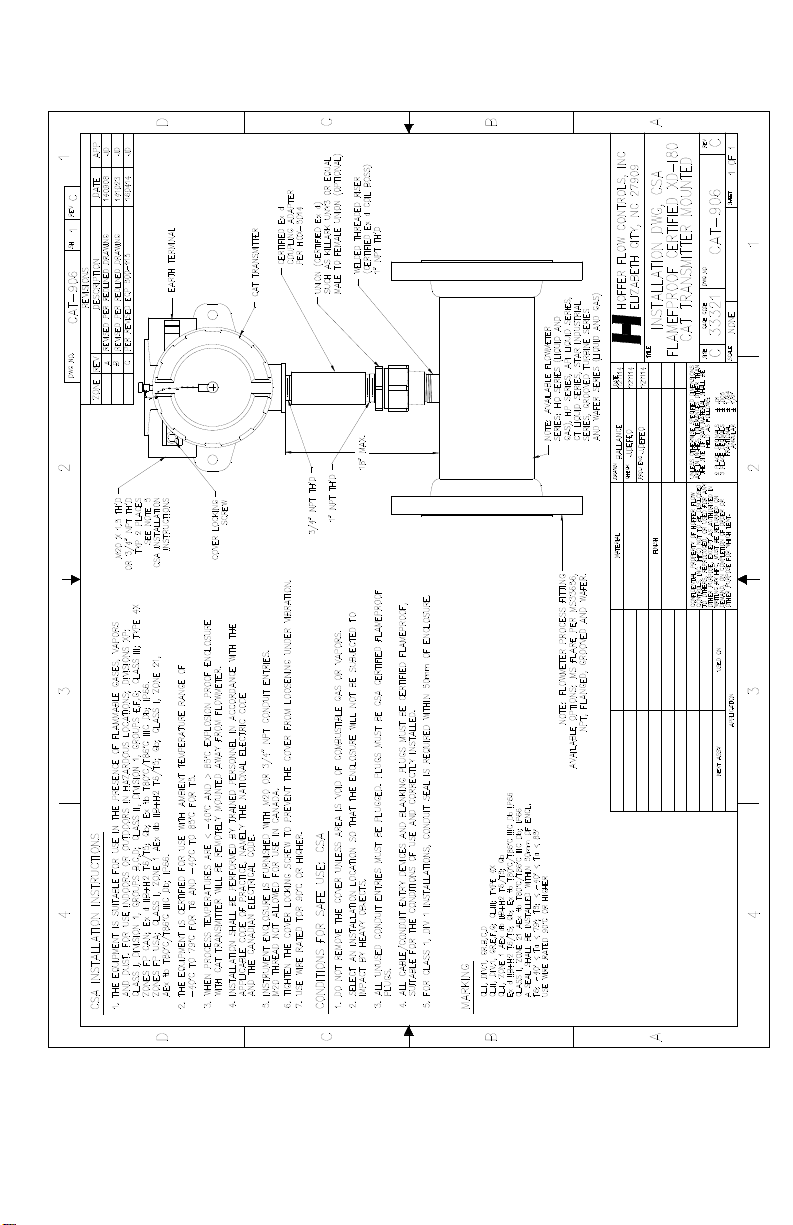
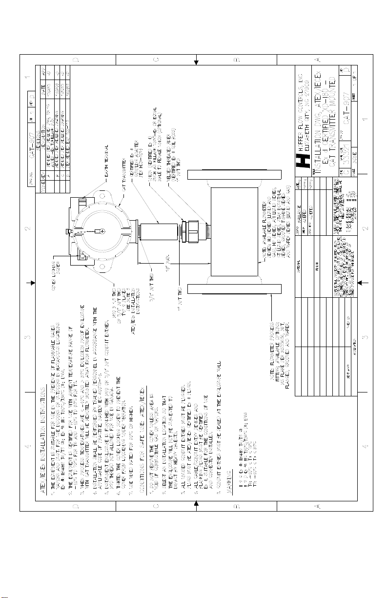
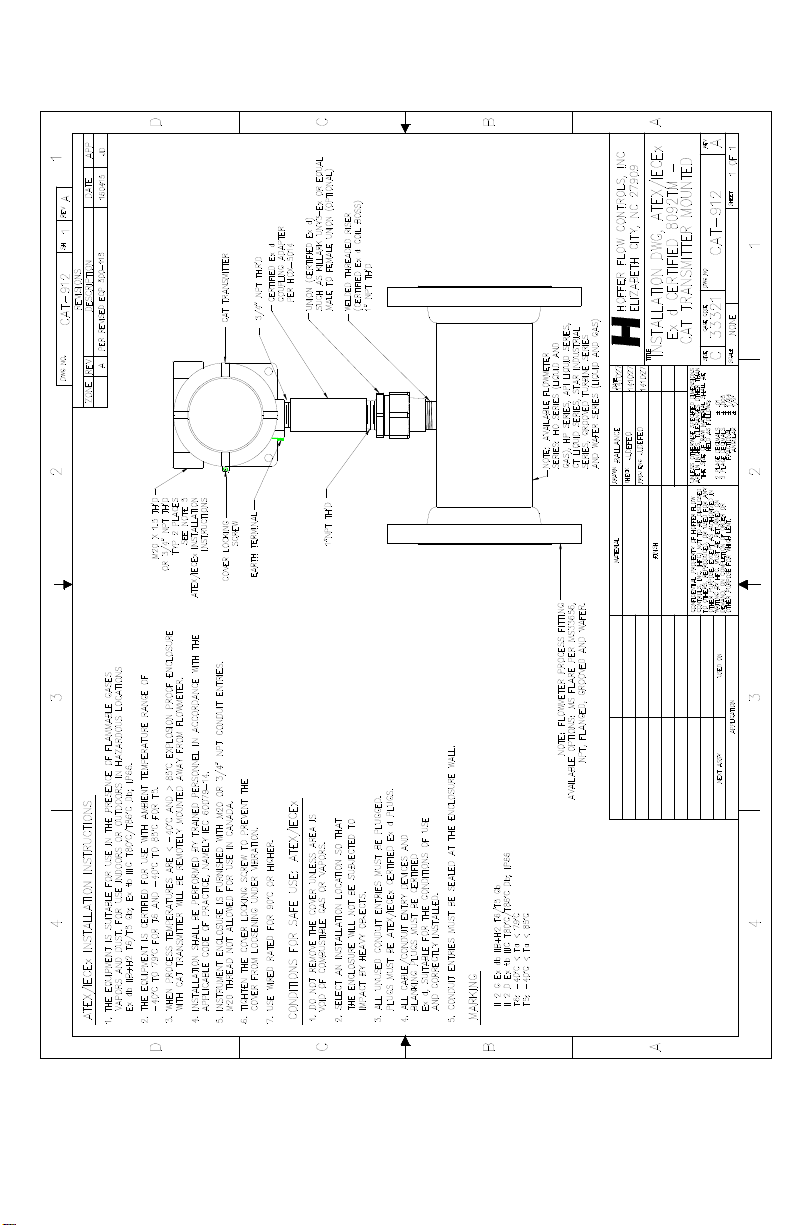
APPENDIX C - Installation and Conditions
for Safe Use Drawings for Certified Systems
HP-312 CAT3
Page 31
Appendix C - Installation and Safe Use Drawings 25
CAT3 HP-312
Page 32
Appendix C - Installation and Safe Use Drawings 26
HP-312 CAT3
Page 33
Appendix C - Installation and Safe Use Drawings 27
CAT3 HP-312
Page 34
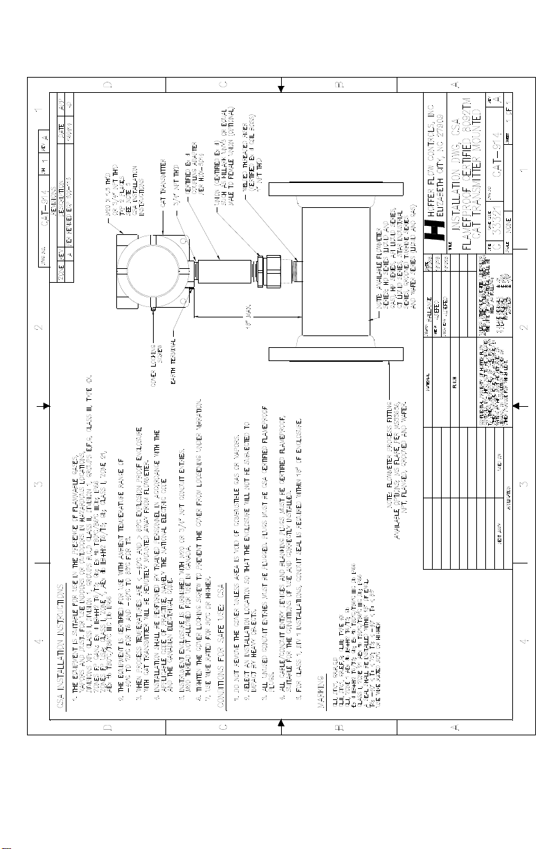
Appendix C - Installation and Safe Use Drawings 28
HP-312 CAT3
Page 35
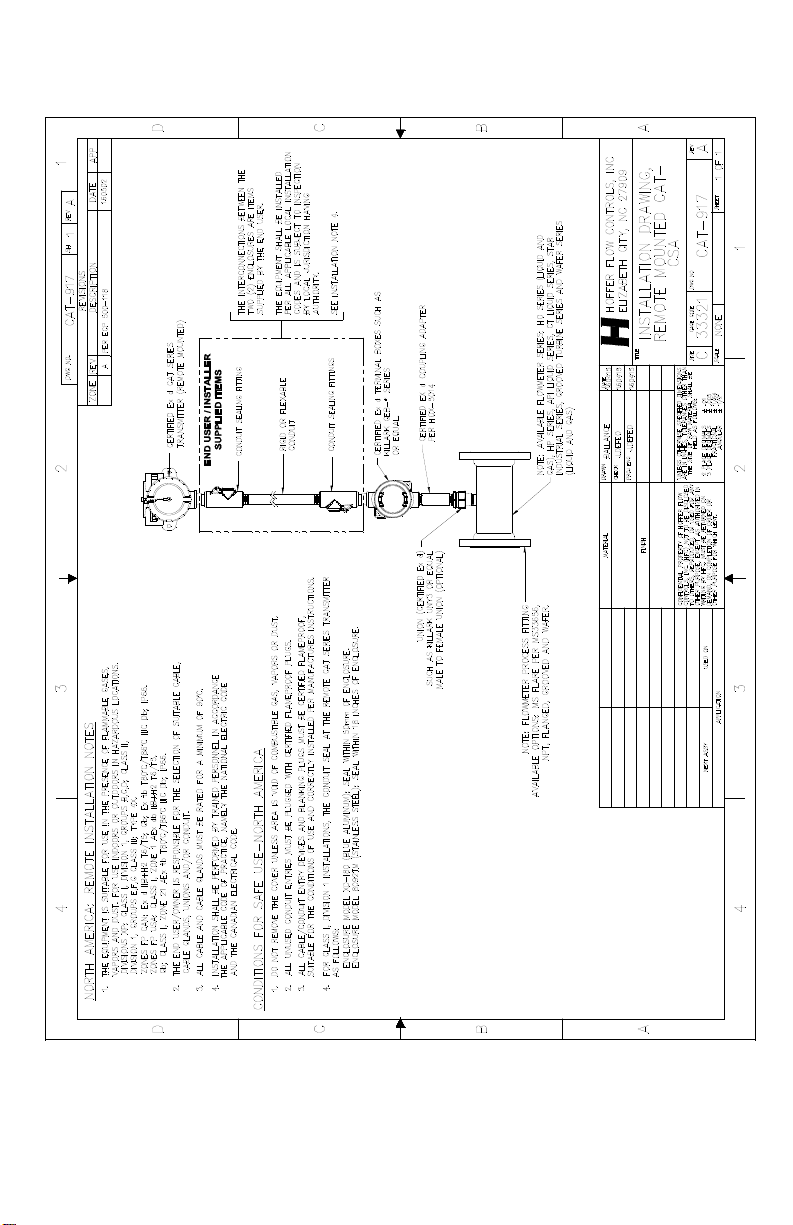
Appendix C - Installation and Safe Use Drawings 29
CAT3 HP-312
Page 36
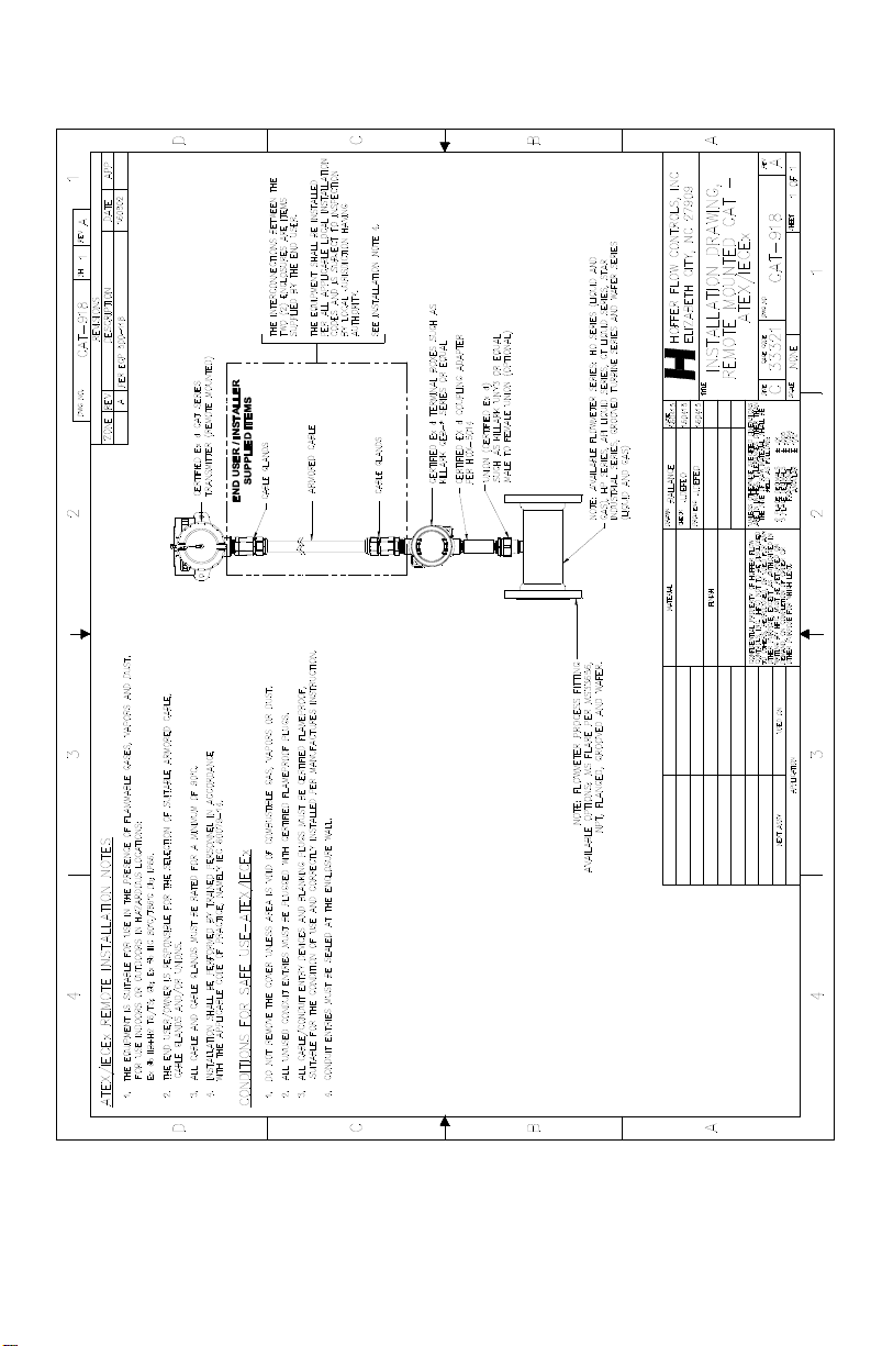
Appendix C - Installation and Safe Use Drawings 30
HP-312 CAT3
 Loading...