

HOESCH Laola II Installation And Operation Instructions Manual
Whirlsystem Laola II
DE
GB
FR
IT
NL
PL
RU
CN
Montage- und Bedienungsanweisung
Installation and operation instructions
Instructions de montage et d’utilisation du kit vapeur.
Istruzioni di montaggio ed uso
Montage- en gebruiksaanwijzing
Instrukcja montażu i obsługi
Инструкция по монтажу и эксплуатации
安装及操作指南

Typ EN03
DE
GB
FR
IT
NL
PL
RU
CN
2
Montage- und Bedienungsanweisung .....................................................................................................................3
Installation and operation instructions ...................................................................................................................14
Instructions de montage et d’utilisation du kit vapeur ............................................................................................25
Istruzioni di montaggio ed uso ...............................................................................................................................36
Montage- en gebruiksaanwijzing ...........................................................................................................................47
Instrukcja montażu i obsługi ..................................................................................................................................58
Инструкция по монтажу и эксплуатации ............................................................................................................69
安装及操作指南 .....................................................................................................................................................80

Inhaltsverzeichnis
01 Allgemeines ...........................................................................................................................................................4
02 Aufstellung/Montage ..............................................................................................................................................4
02.01 „HOESCH Combi-Plus“ (Sonderzubehör) ..............................................................................................................4
02.02 Wasserinstallation ..................................................................................................................................................4
02.03 Elektro-Installation .................................................................................................................................................4
02.03.1 Schutzbereich .........................................................................................................................................................5
02.03.2 Anschlussschaltbild.................................................................................................................................................6
02.03.3 E-Heizung 2 kW (Sonderzubehör) .........................................................................................................................6
03 Probelauf und Dichtigkeitsprobe ............................................................................................................................6
04 Wannenverkleidung ...............................................................................................................................................7
05 Schemazeichnung ..................................................................................................................................................7
06 Ausstattung .............................................................................................................................................................8
06.01 Standardausstattung ...............................................................................................................................................8
06.02 Zusätzliche Ausstattung ..........................................................................................................................................8
07 Bedienungsanleitung .............................................................................................................................................8
08 Einleitung ................................................................................................................................................................9
08.01 Wie funktioniert das Whirlsystem? ..........................................................................................................................9
08.02 Wie funktioniert das Airsystem? ..............................................................................................................................9
09 Funktionen Laola II .................................................................................................................................................9
09.01 Tastatur ...................................................................................................................................................................9
10 Trockenlaufschutz ............................................................................................................................................... 10
11 Autom. Abschalten des Systems ........................................................................................................................ 10
12 Ozonisierung (nur bei Airsystem und Whirl- + Airsystem) .................................................................................... 10
13 Nachblasen (nur bei Airsystem und Whirl- + Airsystem) .................................................................................... 10
14 Desinfektion ........................................................................................................................................................ 10
15 Benutzung und Pfl ege ..........................................................................................................................................11
15.01 Ab- und Überlaufarmatur mit Drehknopf .............................................................................................................. 12
15.02 Überlaufdrehknopf ............................................................................................................................................... 12
15.03 Airdüse ................................................................................................................................................................. 12
16 Checkliste ........................................................................................................................................................... 13
DE
Bitte lesen Sie die Montageanleitung vor der Installation
⚠
sorgfältig durch!
Das System wurde nach folgenden Richtlinien geprüft und ist
berechtigt, diese Zeichen zu führen:
Typ EN03
TÜV Rheinland
I
D
:
1
0
0
0
®
•
0
0
0
0
0
0
3

DE
01 Allgemeines
Alle HOESCH-Whirlwannen werden auf einem selbsttragenden, höhenverstellbaren Untergestell geliefert.
Die Systemkomponenten (Whirlpumpe, Steuerung und Gebläse) sind gemäß beiliegender Maßzeichnung angeordnet.
Bei Modellen, die werksseitig eine Wahlmöglichkeit zwischen „Rechts- oder Linksausführung“ bieten, wird
standardmäßig „Rechtsausführung“ geliefert (immer vom Standpunkt außen vor der Ab-/Überlaufarmatur betrachtet).
Zu beachten:
■ Lieferung auf Vollständigkeit und Beschädigungen überprüfen.
■ Für Schäden durch Transport- oder Zwischenlagerung kann keine Haftung übernommen werden.
■ Wanne nicht am vorinstallierten Rohrsystem anheben! Jegliches Anstoßen vermeiden!
■ Wannenoberfl äche und gefährdete System-Komponenten bei der Installation durch Abdeckung vor
Beschädigungen bzw. übermäßiger Verschmutzung schützen.
■ Die einzelnen System-Kompenenten müssen für spätere Wartungsarbeiten frei zugänglich bleiben!
Personen mit verschiedenen Krankheiten wie z.B. akute Infektionen, Gerinnsel, Nierenversagen, Herzkrankheiten,
Diabetes sollten das Whirlsystem erst nach einer Artztberatung benutzen, was ermöglicht die Anwendung einer
entsprechenden Therapie.
Eine ärtzliche Beratung empfehlen wir ebenso schwangeren Frauen.
Da die Hydromassage für die Kinder erschöpfend ist, sollen sie nicht unbeaufsichtigt in solch einem Bad gelassen werden.
Die vorhandene Einrichtung ist für das Benutzen von Personen (auch Kinder) mit eingeschränkten körperlichen,
sensorischen oder psychischen Fähigkeiten oder Personen, die das Whirlsystem nicht benutzt haben bzw. mit der
Anlage nicht vertraut sind, nicht geeignet. Ausgenommen sind Situationen, in denen es unter Aufsicht oder gem. der
Bedienungsanweisung durch eine verantwortungsberechtigte Person stattfi ndet.
Man man muss auf die Kinder achten, dass sie keinen Zutriff zur Anlage haben.)
Ältere Menschen, die sich langsam bewegen oder behinderte Personen, sollten die Badewannen vorsichtig benutzen.
02 Aufstellung/Montage
Wanne aufstellen und mittels der höhenverstellbaren Kunststoff-Gestellfüße waagerecht ausrichten.
Fuß mit fl acher Kontermutter sichern.
Zur Schalldämmung (Vermeidung von Körperschallbrücken zur Wand) ein handelsübliches
Wandanschlussprofi l (Artikel-Nr. 6915, erforderliches Zubehör) verwenden.
Bei Modellen, die für eine Wandanbindung vorgesehen sind, ist eine Wannenrandaufl age
erforderlich (erforderliches Zubehör: Wannenanker, Artikel-Nr. 690401, gemäß der dort beiliegenden
Montageanweisung montieren).
Bei der Montage darauf achten, dass die Verkleidung den Wannenrand unterstützt!
02.01 „HOESCH Combi-Plus“ (Sonderzubehör)
(Wanneneinlauf mit Spezial Ab-/Überlaufarmatur)
Für die Montage ist ein zusätzlicher Rohrunterbrecher erforderlich. Der Wasseranschluss ist gemäß der dort
beiliegenden Montageanweisung durchzuführen.
02.02 Wasserinstallation
Die Wasser- und Abwasserinstallation ist jeweils nach den örtlichen Vorschriften durchzuführen.
Beim Anschluss an die Trinkwasserinstallation muss bauseitig oder vom Anwender eine den nationalen Anforderungen
entsprechende Sicherungseinrichtung vorgeschaltet werden.
02.03 Elektro-Installation
Hoesch-Whirlwannen sind für den privaten Hausgebrauch und Hotels ausgelegt und entsprechen den einschlägigen
DIN/EN-Vorschriften. Ausgenommen ist eine Verwendung im medizinischen Bereich.
Hinweis:
Sämtliche Elektro-Arbeiten müssen durch Fachelektriker gem. der geltenden DIN/EN, typischen
⚠
Landesvorschriften und örtlichen Stromvorschriften durchgeführt werden!
Das Whirlwannen-System ist ausgelegt für eine Wechselspannung 230 V~AC, 50/60 Hz, 2kW. Die Whirlanlage ist
durch eine separate Stromkreiszuleitung elektrisch zu versorgen und entsprechend der Nennleistungsaufnahme
mit 10 A abzusichern, gemäß dem Typenschild. Weitere Verbraucher dürfen nicht abgezweigt werden. Gemäß den
geltenden Bestimmungen müssen Whirlpoolbäder als elektrische Geräte der Klasse I ständig über einen zweipoligen
Trennschalter an das elektrische System angeschlossen werden. Aus Sicherheitsgründen darf der Anschluss des
Badewannenanschlusskabels an das Stromnetz nur mit einem elektrischen Anschlussstecker erfolgen, der durch einen
Überstromausschalter und einen Differentialschutzschalter (RCD-Gerät) mit einer nominellen Spannung von 30 mA
gesichert ist. Dadurch wird an allen Polen die Installation vom Stromnetz getrennt, wobei die Kontakte mindestens 3 mm
weit geöffnet sein müssen. Das RCD-Gerät muss mindestens einmal monatlich überprüft werden. Es wird empfohlen,
bei Nichtbenutzung des Whirlsystems die Verbindung der Whirlanlage zum Stromnetz durch den Haupt-/FI-Schalter
4
L 1
L 2
L 3
N
PE
Hauptschalter im Bad
(Anordnung außerhalb Zone 2
gem. VDE 0100 Teil 701)
10A träge
RCD 30 mA
Poten]ialausgleich 4 mm²
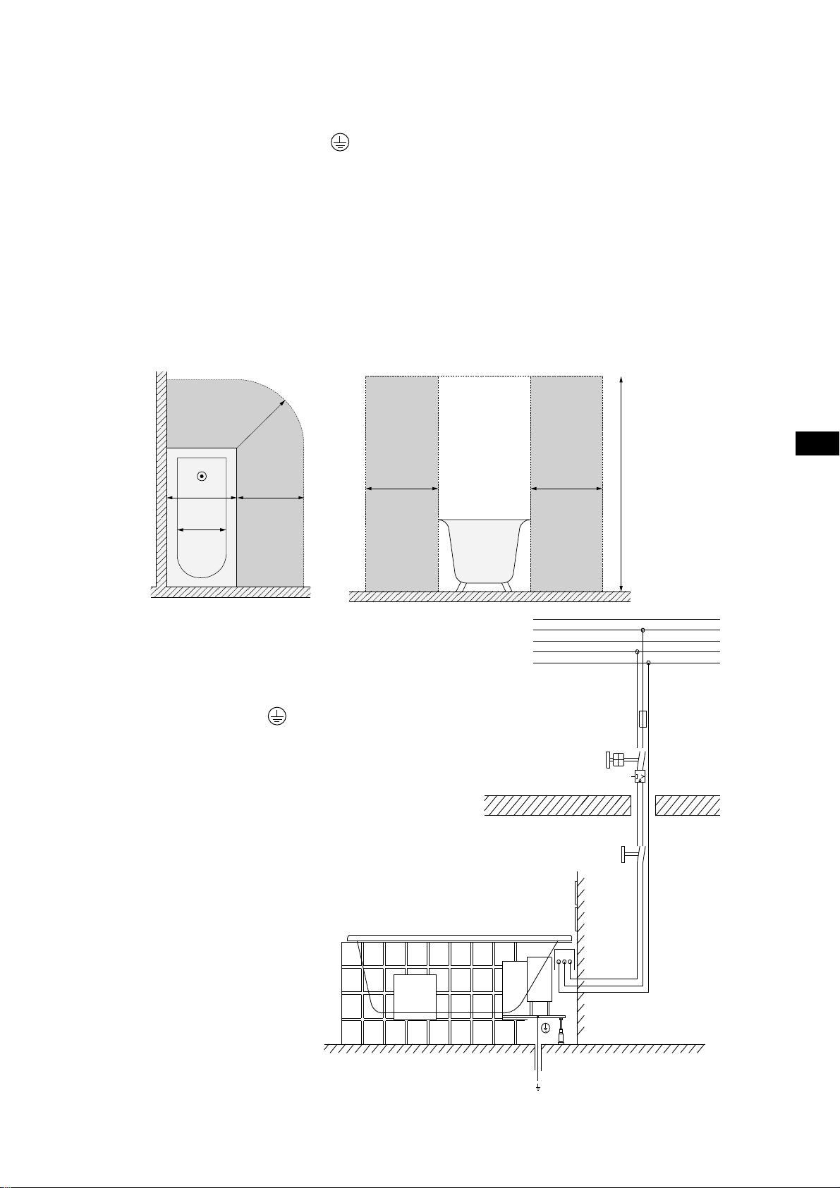
zu unterbrechen. Der Mindestquerschnitt des Badewannenanschlusskabels beträgt 3 x 1,5 mm² (Länge L = 1,8 m).
Bei Badewannen, die mit einem E-Heizer (2kW) ausgerüstet sind, sollte ein Anschlusskabel mit einem Querschnitt von
3 x 2,5 mm² (Länge L = 2,0 m) verwendet werden. Ein fester Stromanschluss der Badewanne sollte in Zone I vorbereitet
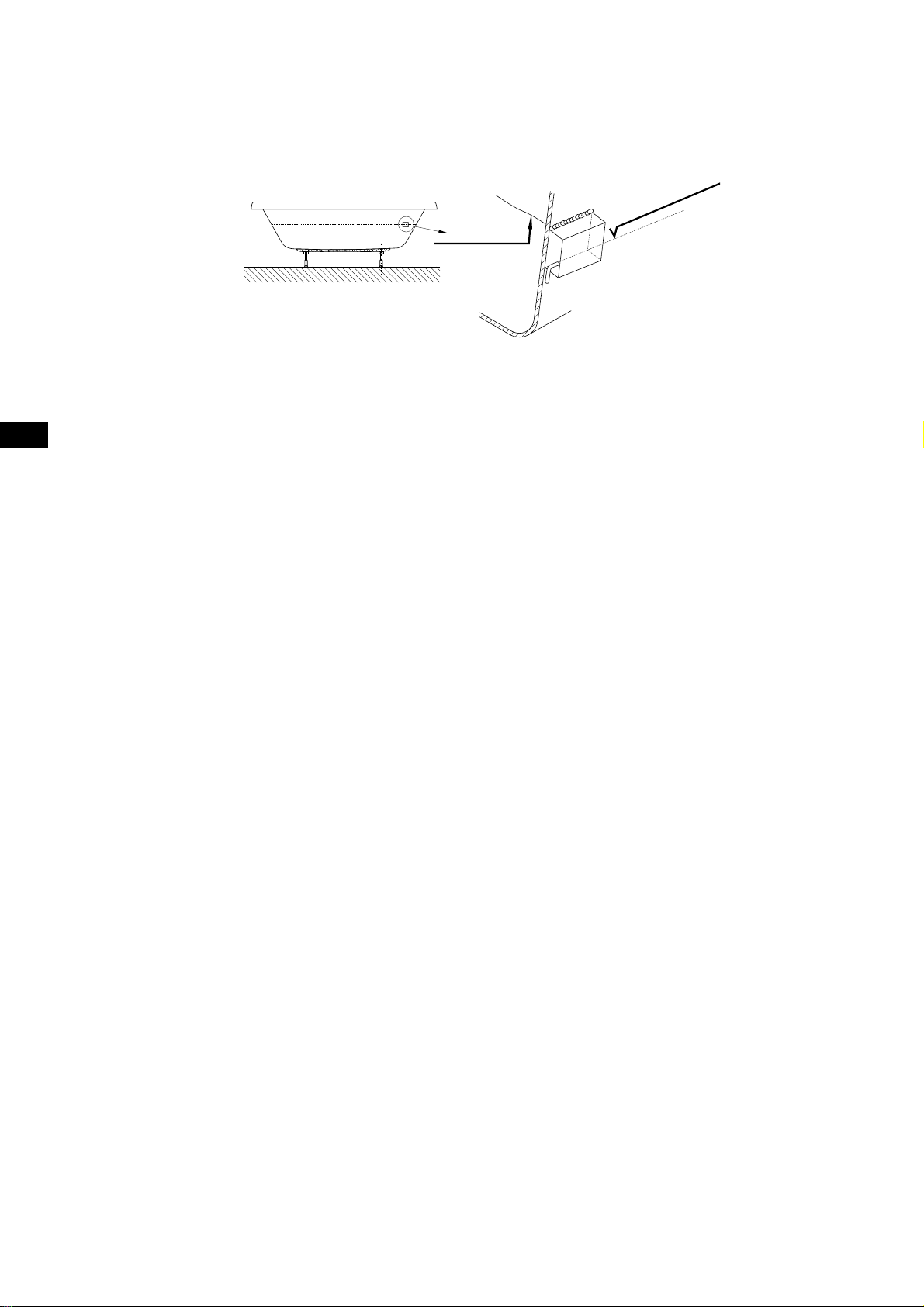
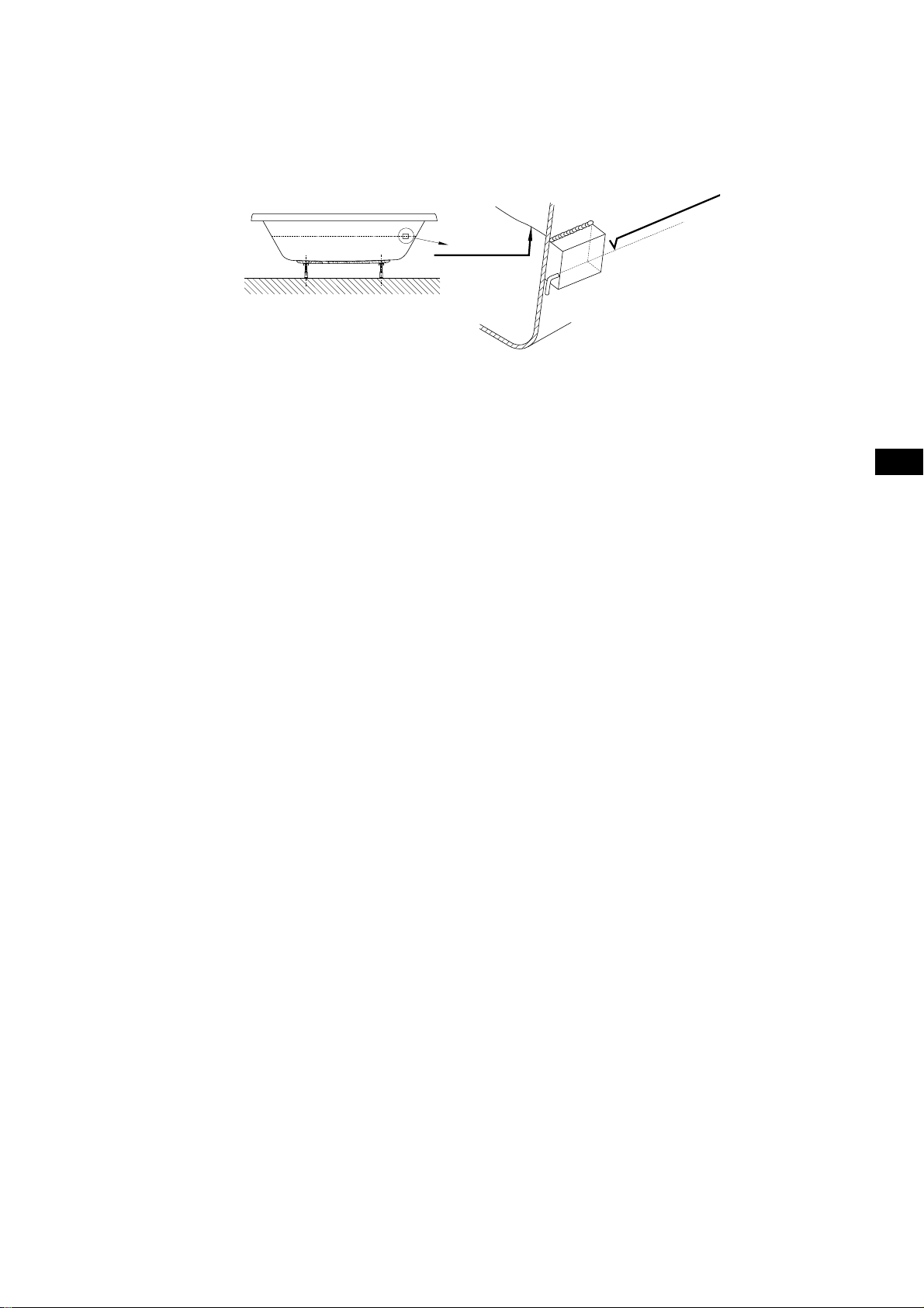
werden (die Einheit befi ndet sich unter der Wanne). Außerdem sollte ein Ausgleichsanschluss zur Verfügung stehen.
Eine markierte Klemmvorrichtung
wird an der Badewanne angebracht, an die ein Ausgleichskabel angeschlossen
werden sollte 4mm².
Der bauseitige Anschluss hat über die fest zu installierende Feuchtraumverteilerdose (IP 65, mindestens 30 cm über
dem Fußboden im Bereich unter der Wanne) zu erfolgen. Bei der Installation einer Badewanne ist auf die Teile zu
achten, die aktive Elemente beinhalten (mit Ausnahme von Elementen mit einer sicheren Niedrigspannung, d. h. mit
einer maximalen Spannung von 12 V), da diese für Personen, die sich in der Badewanne befi nden, nicht zugänglich sein
dürfen.
Der Umstand, dass die Badewanne einen Stromanschluss besitzt, muss in der Garantiekarte mit der Unterschrift und
dem Stempel der autorisierten Person vermerkt werden. Die Karte dient als Nachweis der Gültigkeit der Garantie.
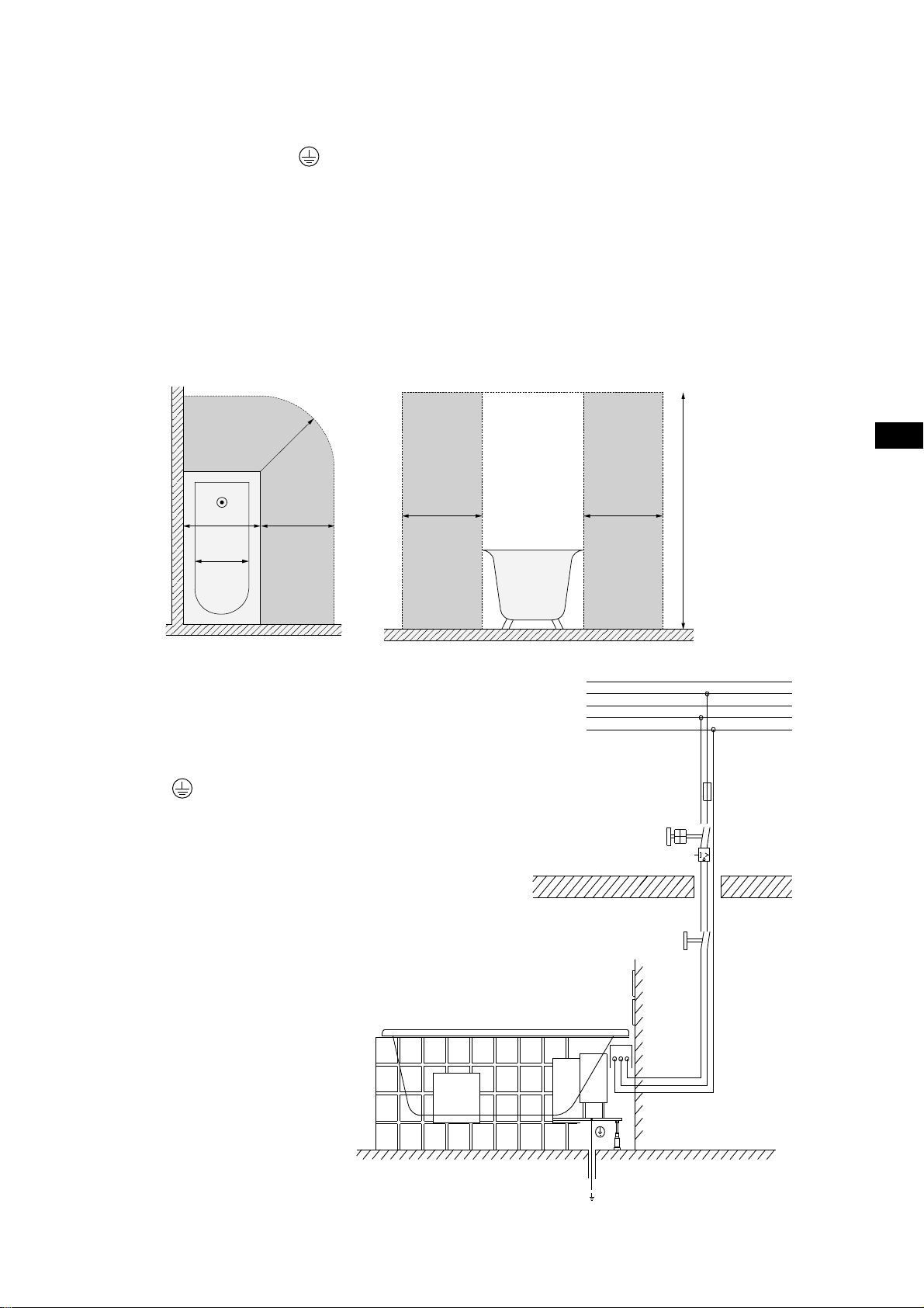
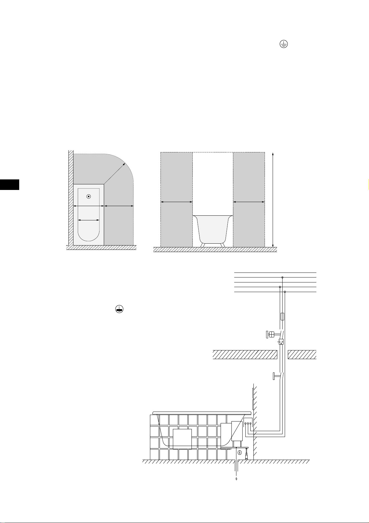
02.03.1 Schutzbereich
r = 60 cm
Bereich 1
Bereich 0
Anlage niemals ohne
⚠
Schutzmaßnahme
(PE,
Vor dem Öffnen spannungsfrei
schalten!
) betreiben!
Bereich 2
60 cm
Bereich 2
60 cm
Bereich 1
Bereich 0
Bereich 2
DE
60 cm
225 cm
5

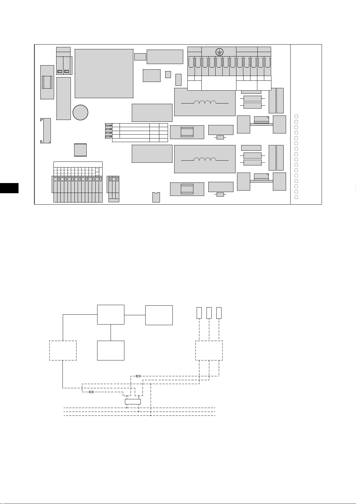
02.03.2 Anschlussschaltbild
DE
/ƍ
water
pump
AIR
NN
blower
L
LIGHT
LN
230V~
L
main
1N AC
WATER
PE
LL'NNLNL
N
PE
L
LIGHT
FUSE
WATER PUMP
FUSE
AIR PUMP
FUSE
KEYBOARD
3 5 41113 141610157 6
2
8 9
SW4 keyboard type
SW3 main freq. set (SW2 - ON)
SW2
SW1
main freq. detect. manual auto
system mode EN.01 EN.02
SWITCH ON OFF
6 keys 5 keys
60Hz 50Hz
EG.01A
5V
SIG
D2
D1
D3
K2
K3K4K5K6D6D5D4
GND
K1
5V
GND
Sensor
02.03.3 E-Heizung 2 kW (Sonderzubehör)
Die Elektro-Wasserheizung 2 kW geht automatisch bei Betrieb der rotierenden Whirldüse in Funktion.
Die Badewasser-Temperatur wird bei ca. 37°C konstant gehalten.
Bei Ausführung mit integrierter E-Heizung 2 kW ist das System werkseitig mit Leistungsteil
und Steuerungs- Komponenten ausgerüstet.
Separaten Netzanschluss für Heizungs-Leistungsteil erstellen und mit 10 A separat absichern.
1
JUDXURVD
2
OLOD
3
ZHL¡
4
VFKZDU]
5
URW
6
EUDXQ
7
JU¾Q
8
JHOE
9
JUDX
10
URVD
11
EODX
12
JU¾QJHOE
13
ZHL¡JU¾Q
14
JUDXURVD
15
EUDXQJU¾Q
16
URWEODX
Polarität gemäß Anschlussplan gewährleisten. Netzanschluss und Betrieb der Anlage nur mit
aufgelegtem Schutzleiter und angeschlossenem Potentialausgleich. Netzanschluss für Systemsteuerung
und Heizungs- Leistungsteil über einen gemeinsamen Fehlerstromschutzschalter 30 mA absichern.
Die Temperaturregelung erfolgt manuell an der E-Heizung. Hierfür ist eine Zugänglichkeit vorzusehen.
1
45
3
2
PE
10 A
10 A
RCD 30mA
230 V~ 50 Hz
L
N
1 - Anschlußklemmen
2 - Steuerung
3 - Heizung
L
L
N
N
PE
PE
4 - Anschlußdose - STB
5 - Anschlußdose PI 65
(bauseits)
03 Probelauf und Dichtigkeitsprobe
Nach den Montageschritten im Punkt 02 bitte zum Probelauf übergehen. Hierzu die Wanne reinigen, mit Wasser
(Temperatur 40 +/- 5 °C) bis zum Überlauf füllen und das Whirlsystem 10 Minuten laufen lassen. Währenddessen
die max. und min. Umdrehungszahl prüfen. Bitte danach das Whirlsystem für etwa 15 Minuten einschalten. Nach
einer Stunde die Dichtheit der Rohrleitungen und Verbindungen prüfen. Bei erneutem Probelauf die Desinfektion gem.
Punkt 14 durchführen.
6
Nach der Montage der Wanne und nach der Dichtiheitsprüfung, spätestens jedoch 24h nach dem Befüllen, wird das
Wasser komplett abgelassen. Danach sollte die Wanne gereinigt werden. In der Rohbauphase muss die Wanne vor
Beschädigungen geschützt wewrden. Anderfalls erlöscht die Garantiebedingung.
04 Wannenverkleidung
Nach dem Probelauf die Wannenverkleidung fertig stellen. Zwischen Wannenrand und Verkleidung einen Spalt von
3-4 mm für eine Silikonabdichtung vorsehen (Verarbeitungshinweise des Herstellers beachten!).
Bei der Verkleidung unbedingt beachten:
1. Alle wannenseitig vorinstallierten, werkseitig angeordneten Leitungssysteme und System-Komponenten müssen
frei hinter der Ummauerung verbleiben.
2. Exponierte System-Komponenten, vor allem Lüfterseite des Pumpenmotors, durch Abdeckung vor
Verschmutzung schützen.
3. Die Verkleidung so gestalten, dass für die System-Komponenten ein Berührungs- und Spritzwasser-Schutz
gewährleistet ist. Betrieb der Wanne ohne Verkleidung ist — außer beim Probelauf — nicht zulässig.
4. Die modellspezifischen Revisionsöffnungen sind mit einem einfachen Zugang und freier Öffnung
von mindestens 400 bis 450 mm Breite sowie 350 mm Höhe gemäß der beiliegenden Maßzeichnung
anzuordnen.
Zusätzlich ist eine Revisionsöffnung im Ablaufbereich vorzusehen.
Der Revisionseinsatz darf nur mit Werkzeug geöffnet werden. Die Maße sind unbedingt einzuhalten, da nur
dann bei eventuell erforderlichen Wartungen eine problemlose Ausbaumöglichkeit für die technischen SystemKomponenten gewährleistet ist. Ideal ist das HOESCH- „Lüftungs-/Revisionsgitter“ mit den Abmessungen
420 x 325 mm (Artikel-Nr. 6683.---).
5. Eine freie Luftzufuhr (ca. Vo = 60,0 m³/h bei max. Gebläsedrehzahl) ist bei den rotierenden Whirldüsen und dem
Gebläse zu gewährleisten, da bei hermetisch abgedichteter Verkleidung die Luftversorgung der rotierenden
Whirldüsen und des Gebläses unterbunden ist. Vollkommen ausreichend ist eine Öffnung von 100 x 100 mm in
der Verkleidung. Bei Einsatz des „Lüftungs-/Revisionsgitter“ ist eine ausreichende Luftzufuhr gewährleistet.
DE
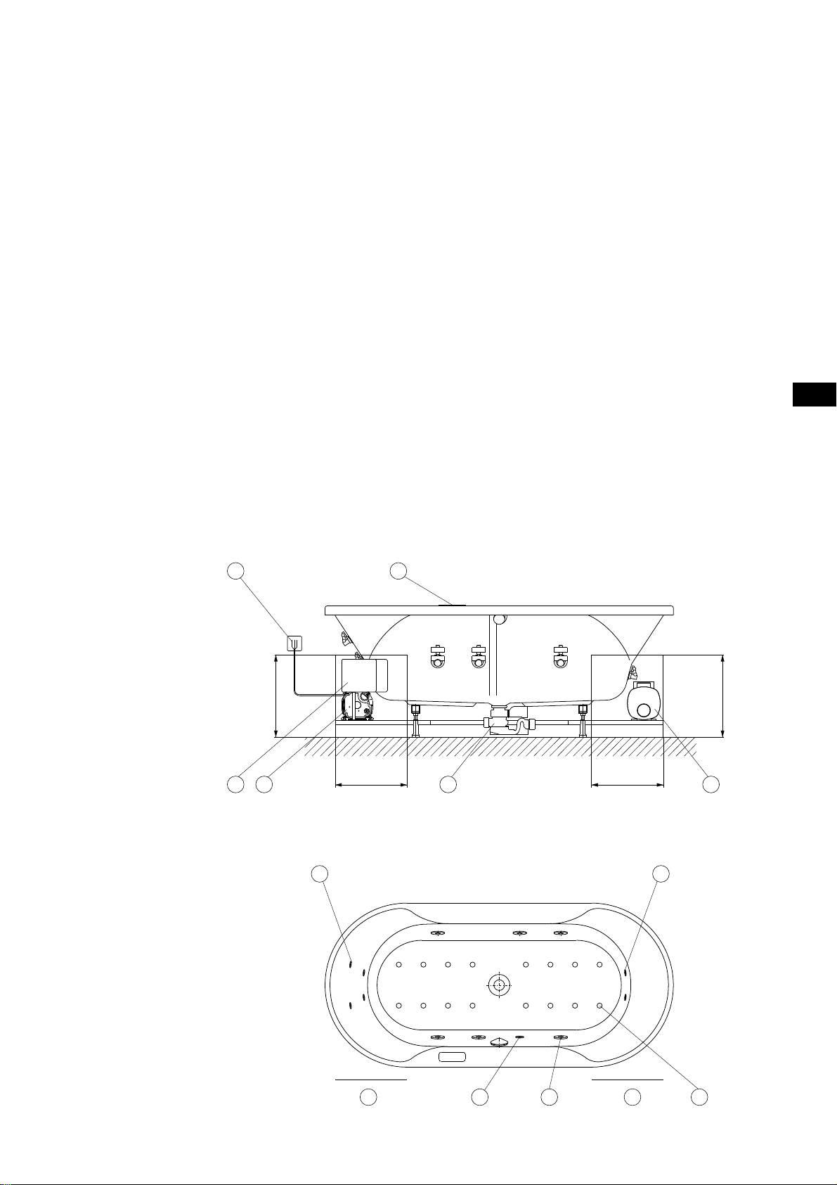
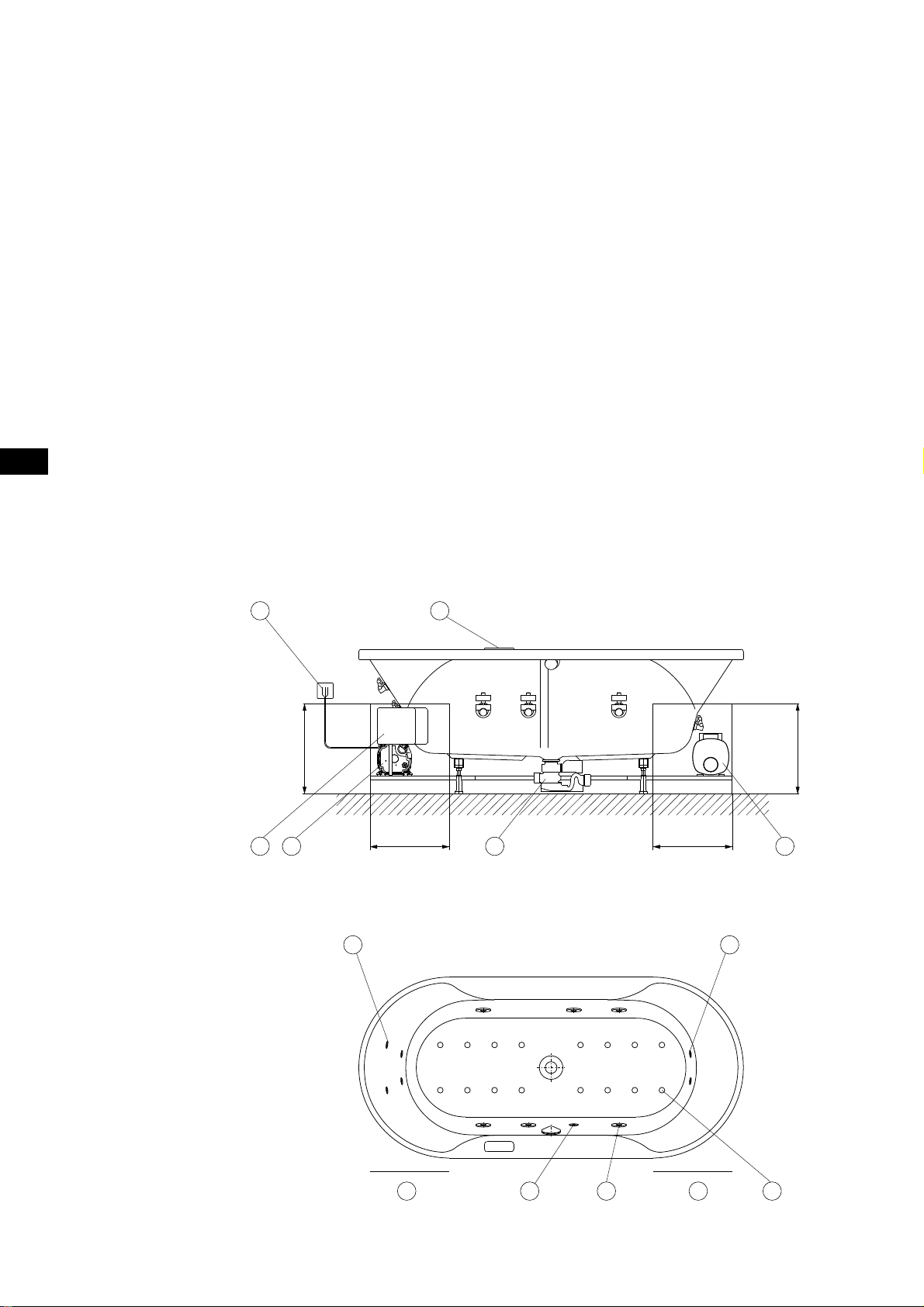
05 Schemazeichnung
1 2
3
min.400
4 5 6
350
7
350
9
min.400
1 Netzanschluss Steuerung 230 V~, 50/60 Hz,
10 A Anschlussdose bauseits
2 Tastatur
3 Steuerung
4 Gebläseeinheit
5 Abwasseranschluss
6 Pumpe
7 Rückendüse (Sonderzubehör)
8 LED-weiß
9 Fußdüse (Sonderzubehör)
10 Revisionsöffnung
11 Whirldüse
12 Bodendüse
Ø
40/50
10 10
8
11 12
7
DE
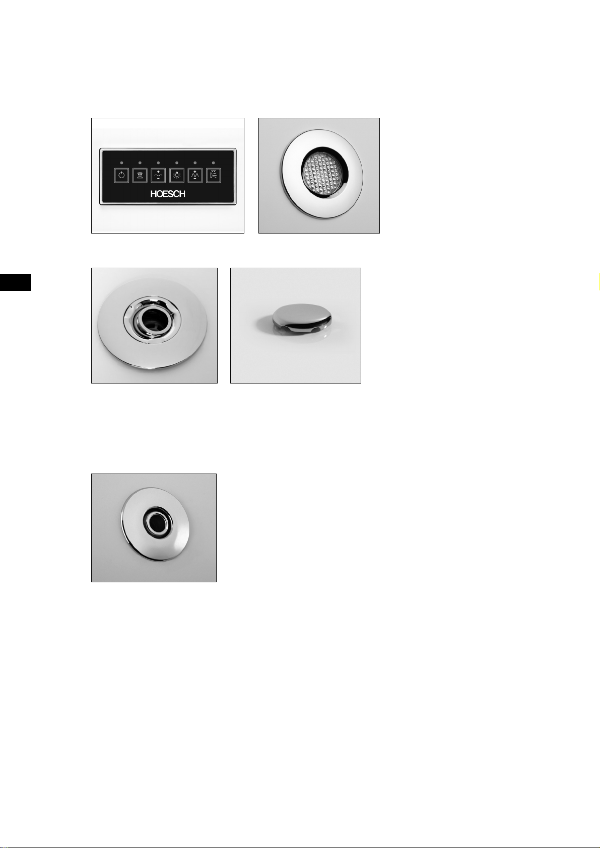
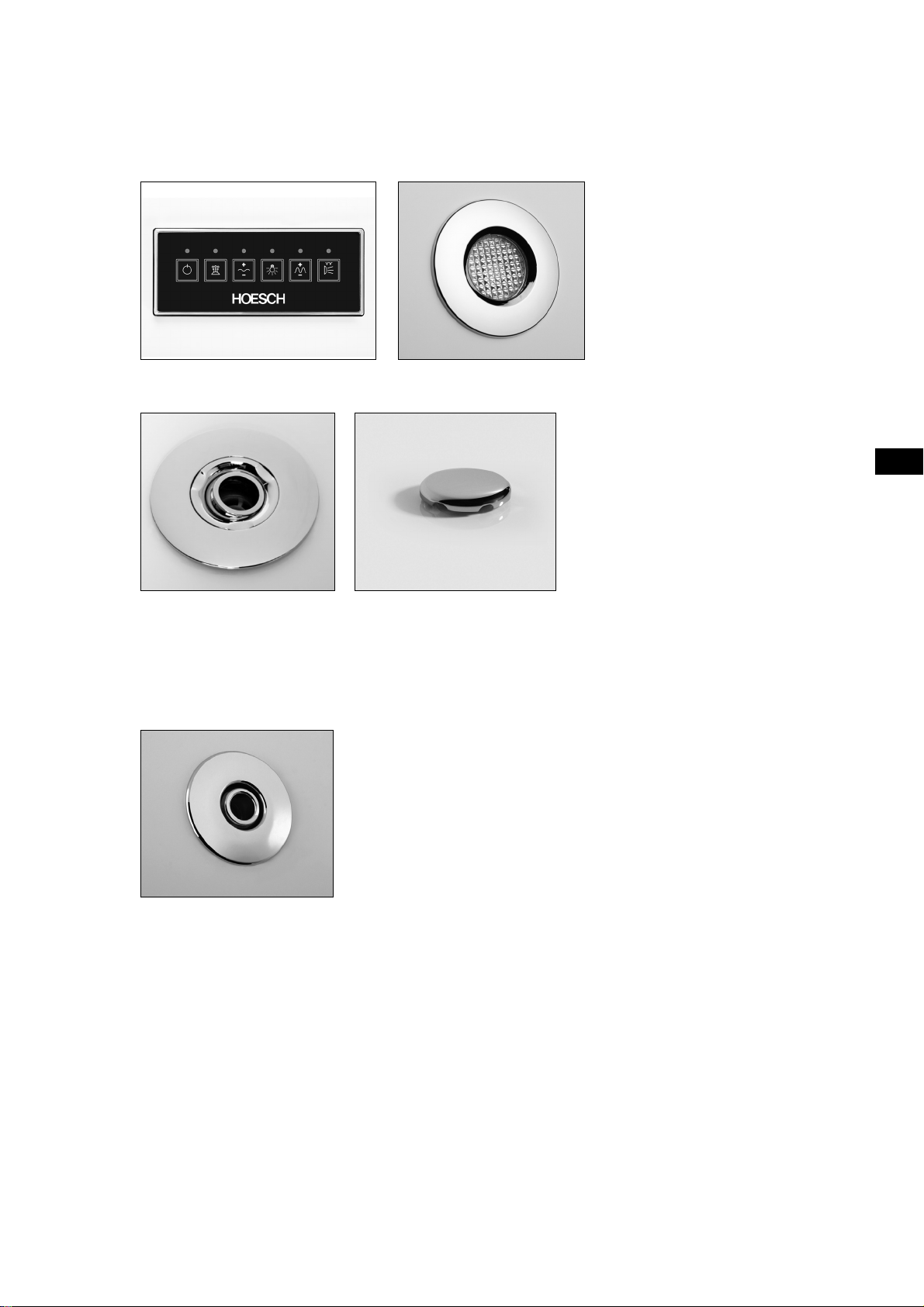
06 Ausstattung
06.01 Standardausstattung
Tastatur LED-weiß
Whirldüse
(Whirlsystem
und Whirl- + Airsystem)
Airdüse
(Airsystem
und Whirl- + Airsystem)
06.02 Zusätzliche Ausstattung
Fuß- und Rückendüse
(Whirlsystem
und Whirl- + Airsystem)
07 Bedienungsanleitung
Es ist soweit: Das erste Bad in Ihrer HOESCH-Whirlwanne steht bevor! Wir wünschen Ihnen viel Freude an Ihrer
neuen Wanne! Ständige Produktionsüberwachung, Forschung und Weiterentwicklung, verbunden mit dem
innovativen Design unserer Luxuswannen aus Sanitär-Acryl, gewährleisten, dass Sie sich für ein hochwertiges
Qualitätsprodukt entschieden haben. Für ungetrübten Badespaß bitten wir Sie, diese Bedienungsanleitung vor
dem ersten Bad sorgfältig zu lesen.
8
08 Einleitung
08.01 Wie funktioniert das Whirlsystem?
Das Whirlsystem bildet einen geschlossenen Wasserkreislauf. Das Ablaufventil ist gleichzeitig Ansaugstutzen. Wasser
wird angesaugt, durch die Whirlpumpe beschleunigt und mit ca. 1 bar Druck durch die Whirldüsen ins Innere der Wanne
geleitet. Durch Unterdruck wird die selbsttätige Luftbeimischung des Wasserstrahls erreicht. Die Leitungen zwischen den
Whirldüsen und der Whirlpumpe sind so angeordnet, dass sie sich beim Ablassen des Badewassers entleeren.
08.02 Wie funktioniert das Airsystem?
Vom Gebläse angesaugte Luft wird durch die Luftkanäle unterhalb des Wannenbodens sowie die Bodendüsen ins Innere
der befüllten Wanne geleitet.
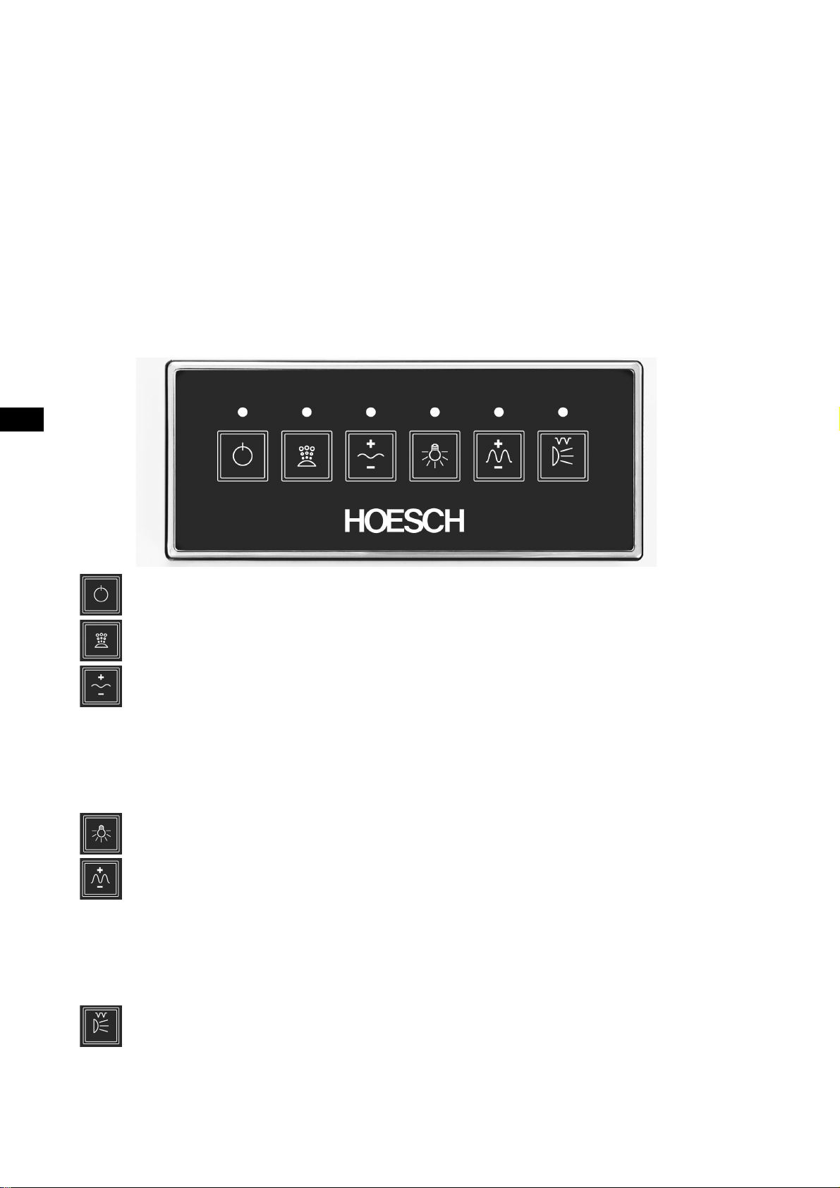
09 Funktionen Laola II
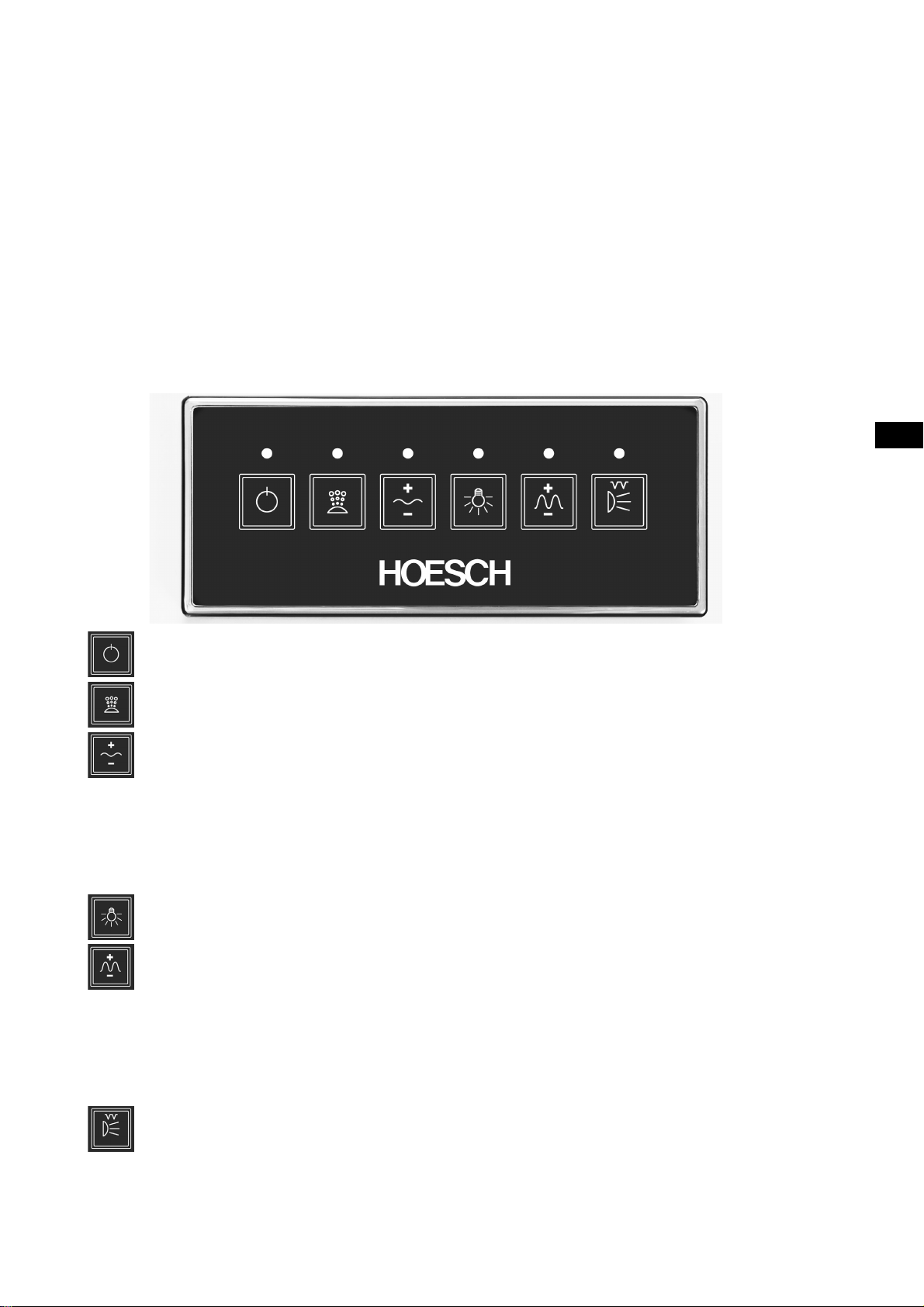
09.01 Tastatur
8 9 10 11 127
134562
1 Alles Aus
Ausschalten sämtlicher Funktionen.
2 Taste Gebläse Ein/Aus. Kurzes Drücken der Taste 2 schaltet die Pumpe
mit der Leistung von 60% ein. Das Drücken dieser Taste während des
Betriebs, schaltet die Pumpe aus.
3 Taste zur Leistungsregelung der Gebläse und des Welleneffektes
aus den Luftdüsen. Die Taste ist während des Betriebs der Gebläse
aktiv. Kurzes Drücken der Taste 3 ändert die Gebläsenleistung. Die
Regelung ist wie folgt: das weitere Drücken der Taste führt zur maximalen
Drehanzahlsteigerung. Nachdem die Pumpe die maximale Drehanzahl
erreicht hat und die Taste 3 immer noch gedrückt wird, wird die Drehzahl
der Pumpe bis zum Minimalwert reduziert. Der Einstellungsbereich
der Pumpendrehzahl: ca. 30 - 100%. Taste 3 mindestens 5 Sekunden
gedrückt halten, somit wird der Welleneffekt aus den Luftdüsen betätigt.
Das Drücken der Taste 3 während der Welleneffekt aktiv ist, schaltet die
Welle aus und stabilisiert die Drehzahl auf dem aktuellem Niveau.
4 Taste Licht Ein/Aus.
5 Taste zur Leistungsregelung der Wasserpumpe. Die Taste ist während
des Betriebs der Wasserpumpe aktiv. Das weitere Drücken der Taste führt
zur Änderung der Leistung der Wasserpumpe. Die Einstellung erfolgt wie
folgt: das aufeinander folgende Drücken der Taste führt zur maximalen
Drehzahlsteigerung. Nachdem die Pumpe die maximale Drehzahl erreicht
hat und die Taste 5 immer noch gedrückt wird, wird sich die Drehzahl
der Pumpe bis zum Minimalwert reduzieren. Der Einstellungsbereich der
Pumpedrehzahl: ca. 50 - 100%. Taste 5 zumindest 5 Sekunden gedrückt
halten, somit wird der Welleneffekt aus den Wasserdüsen betätigt. Das
Drücken der Taste 5 während der Welleneffekt aktiv ist, schaltet die Welle
aus und stabilisiert die Drehzahl auf dem aktuellem Niveau.
6 Taste Wasserpumpe Ein/Aus. Kurzes Drücken der Taste 6 schaltet die
Pumpe mit der Nennleistung von 60% ein. Kurzes Drücken dieser Taste
während des Betriebs schaltet die Pumpe aus. Taste 6 durch 5 Sekunden
gedrückt halten (während die Pumpe im Betrieb ist), schaltet die pulsierende
Massage ein (Wasserpumpe wird in den wiederholenden Zyklen im Betrieb
sein: 3 Sekunden - max. Drehzahl, 2 Sekunden - min. Drehzahl).
DE
7 Rote LED zeigt Betreibsspannung und
Betriebsbereitschaft des Gerätes an,
Dauerlicht - die Steuerung im Betrieb,
Wasserniveau erreicht
kein Leuchen - keine Betriebsspannung
der Steuerung,
""langsames"" pulsierendes Leuchten
(1 Sekunde) - ""STANDBY"" Modus - die
Steuerung ist mit Strom versorgt, kein
Betrieb
(Zeitabmessen bis zur Trocknung)
8 Blaue LED zeigt den Betrieb der Gebläse
an.
Dauerlicht - Gebläse im Betrieb,
(Zeitabmessen bis zur Trocknung)
kein Leuchen - Gebläse nicht im Betrieb,
9 Blaue LED zeigt die Änderung der
Gebläsendrehzahl an,
Dauerlicht - Welleneffekt aus den
Luftdüsen aktiv (kontinuierliche Änderung
der Pumpendrehzahl)
kein Leuchten - Wellenefekt nicht im
Betrieb
10 Blaue LED zeigt den Betrieb des Licht an.
11 Blaue LED zeigt die Drehhzahländerung
der Wasserpumpe an,
Dauerlicht - Welleneffekt aus den
Wasserdüsen aktiv (kontinuierliche
Änderung der Pumpendrehzahl)
kein Leuchten - Wellenefekt nicht im
Betrieb
12 Blaue LED zeigt den Betrieb der
Wasserpumpe an.
Dauerlicht - Wasserpumpe im Betrieb,
kein Leuchten - Wasserpumpe nicht im
Betrieb,
9
DE
10 Trockenlaufschutz
Ihre HOESCH Whirlwanne Laola II ist mit einem Trockenlaufschutz ausgestattet. Die Whirlpumpe, bzw. die Desinfektion
können erst gestartet werden, wenn ein bestimmter Wasserstand erreicht ist. Der Trockenlaufschutz verhindert, dass
das System bei leerer Wanne oder zu geringem Wasserstand in Betrieb genommen wird.
Oberkante der
min. Füllhöhe
min. Füllhöhe =
obersten Düse
11 Autom. Abschalten des Systems
Die Betriebsdauer des Systems ist auf eine Nutzungsdauer von 20 Minuten begrenzt. Nach 20 Minuten - unabhängig
von Tastenbetätigungen - schaltet das System automatisch ab. Durch Drücken der Tasten 1 und/oder 5 kann das jeweilige
System wieder eingeschaltet werden.
12 Ozonisierung (nur bei Airsystem und Whirl- + Airsystem)
Die Ozonisierung erfolgt automatisch mit Einschalten der Gebläseeinheit.
13 Nachblasen (nur bei Airsystem und Whirl- + Airsystem)
Das Nachblasen startet nach Entleerung der Wanne und einer Wartezeit von ca. 10 Minuten automatisch. Die Dauer
beträgt insgesamt ca. 2 Minuten, wobei das Gebläse zunächst 30 Sekunden auf mittlerer Leistung und anschließend
90 Sekunden bei maximaler Leistung aktiviert wird.
Während der Zeitabmessung zum Trocknungsbeginn und während des Trocknungsprozesses sind die Tasten 1,2 und 4 aktiv.
2 + 4 - beim gleichzeitigen Drücken der beiden Tasten, startet sofort die Pumpe, obwohl die Zeit zum Trocknungsbeginn
nicht beendet wurde.
1 - Beim Drücken der Taste während des Betriebs wird die Pumpe ausgeschaltet.
Drücken der Taste während der Zeitabmessung zum Trocknungsbeginn, verursacht das Löschen des Vorgangs.
14 Desinfektion
Die regelmäßige Desinfektion Ihrer Whirlwanne sorgt für eine optimale Hygiene. Wir empfehlen daher, die
Desinfektion einmal im Monat oder nach jedem 2.-3. Badevorgang durchzuführen.
Wichtig: Bei längerer Zeit der Nichtbenutzung sollte die Whirlwanne vor Inbetriebnahme in jedem Fall
⚠
desinfi ziert werden!
Zur Desinfektion ist ein bestimmter Wasserstand erforderlich – ggf. muss der Wasserstand bis zu dem Niveau
erhöht werden, bei dem auch die Lichtfunktion gestartet werden kann.
Für Schäden und Gefahren, verursacht durch andere, für diesen Einsatzzweck nicht geeignete Mittel,
⚠
übernehmen wir keine Haftung!
■ Nach dem Verlassen der Wanne ist Desinfektionsmittel (Angaben des Herstellers beachten!) in die Wanne
zu geben. Wir empfehlen die Verwendung der Desinfektionsmittel Art.-Nr.: 6923 oder Art.-Nr.: 133607.
Empfohlene Dosierung: 100 ml Desinfektionsmittel pro 100 L Wasserinhalt der Wanne. Dabei sind die Angaben
des Herstelles sorgfältig zu beachten.
■ Manuelle Desinfektion durch Drücken der Airtaste bzw. der Whirltaste (je nach System) starten.
10

Ablauf der manuellen Desinfektion
■ Nach Zugabe des Desinfektionsmittels muss das Whirl-(Seitendüsen/Pumpen) / Airsystem (Bodendüsen/
Gebläse) bzw. Whirl-Airsystem zur Verteilung des zugegebenen Desinfektionsmittel manuell gestartet und nach
1 Minute manuell wieder abgeschaltet werden.
■ Nach einer Einwirkzeit von 30 Minuten muss das System nochmals manuell für 2 Minuten in Betrieb genommen
werden (manueller Start / Stop).
■ Nach Ende der Desinfektion ist die Wanne zu entleeren.
15 Benutzung und Pfl ege
Benutzung
Im Allgemeinen ist das Baden in einer Whirlwanne eine Erholung bzw. ein großer Badespaß. Für einige wenige
Personen könnte es möglicherweise zu Gesundheitsrisiken kommen.
Im Zweifel holen Sie bitte den Rat Ihres Arztes ein.
Bei folgenden Personengruppen bzw. Anwendern raten wir von einer Benutzung der Whirlwanne ab:
■ Säuglinge bis zur Vollendung des 1. Lebensjahres
■ Menschen mit labilem Kreislauf
■ Nach starkem Alkoholgenuss
■ Während einer Erkältungskrankheit oder Grippe
■ Bei Herz-/Kreislaufbeschwerden
■ Unmittelbar nach dem Saunabad (längere Abkühlphase abwarten)
■ Unmittelbar nach dem Essen
■ Benutzen Kinder die Whirlwanne ist eine ständige Beaufsichtigung durch Erwachsene sicherzustellen.
■ Benutzen ältere oder behinderte Personen, die in Ihrer Bewegung eingeschränkt sind, die Whirlwanne, so sollte
man besondere Sorgfalt walten lassen.
■ Die Fachbetriebe und der erste Eigentümer der Whirlwanne erklären, den nachfolgenden Eigentümern und
Benutzern die Bedienungsanleitung zur Verfügung zu stellen.
DE
Die Wassertemperatur in der Whirlwanne soll die durchschnittliche Körpertemperatur nicht überschreiten. Der ideale
Temperaturbereich liegt bei + 32°C bis + 37°C.
Stellen Sie sicher, dass keine Elektrogeräte oder andere stromführende Bauteile in die befüllte Whirlwanne fallen können,
um somit Ihre Sicherheit nicht zu gefährden.
Pflege
Badezusätze die Feststoffe enthalten, z. B. Moorbäder, Ölbäder usw. dürfen nicht verwendet werden.
Wir empfehlen die Verwendung von HOESCH Schaumbädern für Whirlwannen.
Nach dem Baden Wannenoberfl äche mit Wasser abspülen und mit einem feuchten Tuch nachwischen.
Keine Scheuermittel verwenden! Für gelegentliche Grundreinigungen ein paar Spritzer Reinigungsmittel auf
die Oberfl äche geben und mit einem weichen Tuch nachreiben. Stärkere Verschmutzungen mit warmem Wasser und mit
fl üssigem, milden Reinigungsmittel oder einer Seifenlauge beseitigen.
Kalkablagerungen mit Branntweinessig und Wasser wegwischen (Armaturen aussparen!). Bei Einsatz
von Abfl ussreinigern die Gebrauchsanweisung beachten!
Leichte Kratzer oder aufgerauhte Stellen bei glänzender Oberfl äche z. B. mit HOESCH Pfl egeset, Art.-Nr.: 6991 00
entfernen.
Hinweis:
Armaturen und Einbauteile nur mit einem weichen Tuch reinigen. Schäden, die durch unsachgemäße Behandlung
mit Chemikalien, Säuren oder Scheuermitteln entstehen, können wir nicht als Reklamationsgrund anerkennen.
11

DE
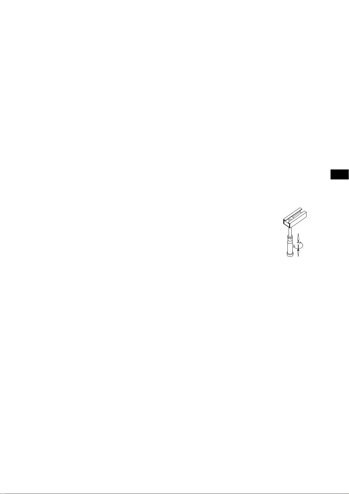
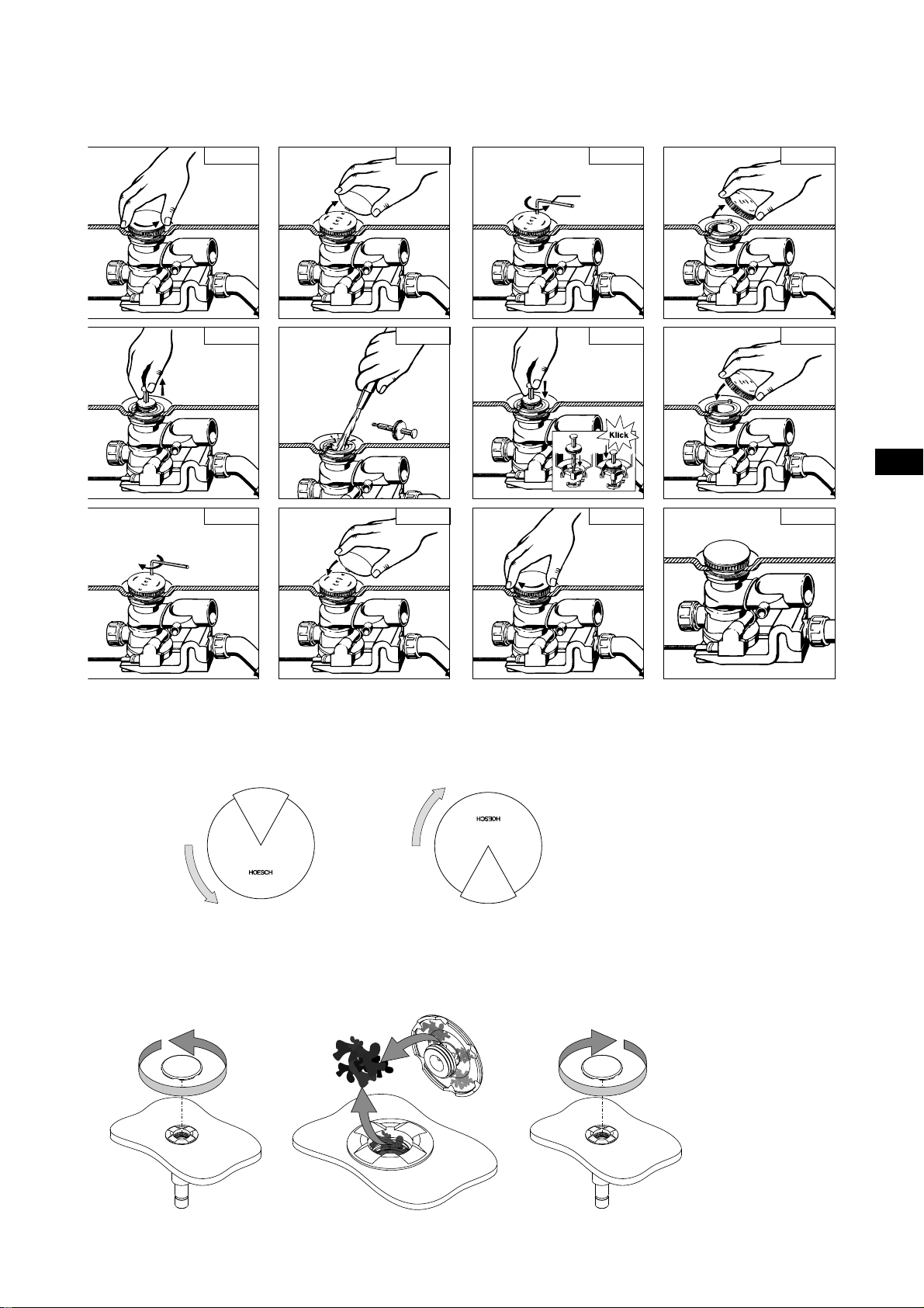
15.01 Ab- und Überlaufarmatur mit Drehknopf
Reinigung/Wartung mit Inbus M4
12 34
Bild Bild Bild Bild
56 78
Bild Bild Bild Bild
9101112
Bild Bild Bild Bild
M 4
Achtung: Bei Verwendung der HOESCH Combi-Plus ist zusätzlich ein Rohrunterbrecher notwendig!
15.02 Überlaufdrehknopf
Ablauf schließen Ablauf öffnen
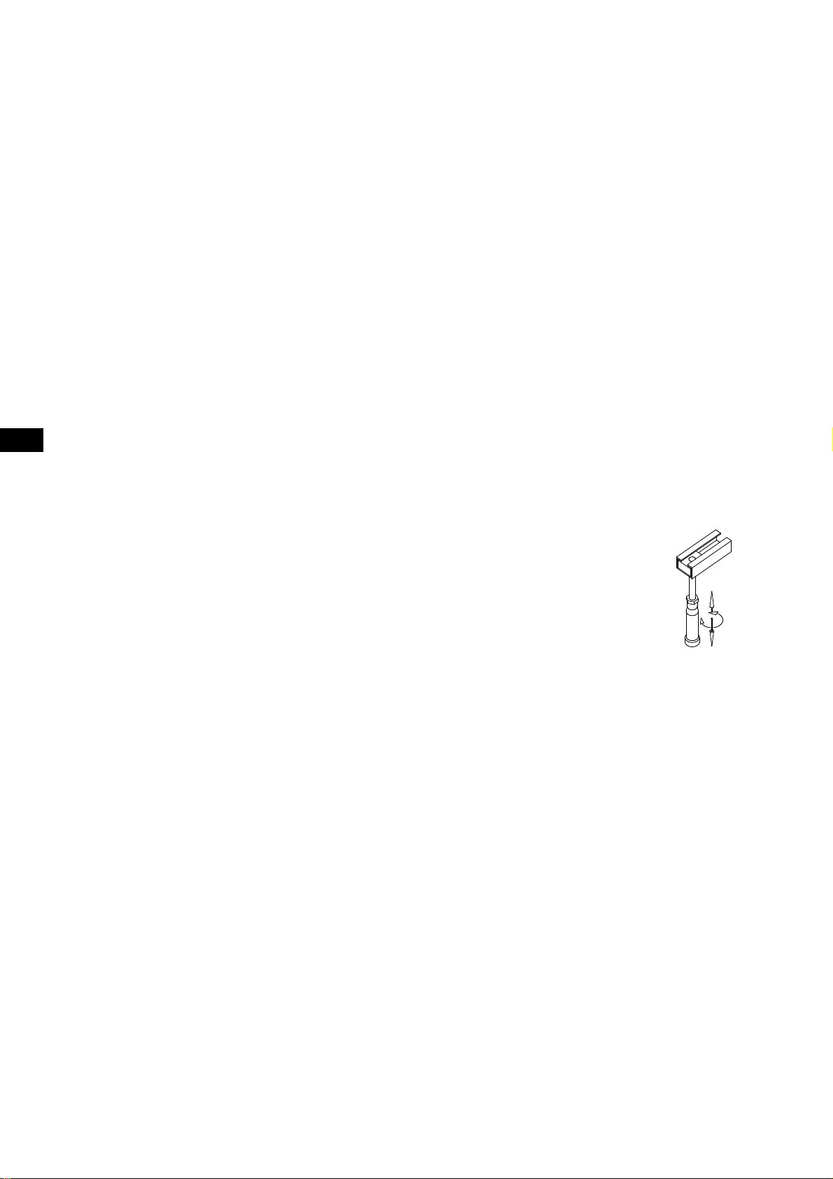
15.03 Airdüse
12 3
12
16 Checkliste
Anhand dieser Checkliste können auftretende Störfälle an Ihrer Whirlwanne schnell und unproblematisch behoben
werden. Arbeiten an der elektrischen Einrichtung sind nur autorisiertem Fachpersonal vorbehalten. Die Whirlwanne ist
vorher vom Stromnetz zu trennen!
Störungen Ursache Abhilfe
Gebläse läuft nicht
Pumpe läuft nicht
Massagestrahl wird schwächer Ablaufventil Ablaufventil säubern siehe Punkt 13.01
Netzspannung 230 V, 50 Hz fehlt Vorsicherung und/oder Fehlerstrom-
Feinsicherung durchgebrannt Auswechseln der Sicherung durch eine
Trockenlaufschutz aktiviert Wasser nachfüllen, bis grüne LED im
Motorschutzsicherung wegen
Überhitzung ausgelöst
Steuerungselektronik Reset durchführen, d. h. die Stromzufuhr
Massagedüsen Reinigung der Düsen
Schutzschalter (FI) einschalten
Fachkraft
Display erscheint
Motor einige Minuten abkühlen lassen
ist für ca. 1 Minute zu unterbrechen
Was ist zu tun, wenn ...
sich während dem Whirlbaden Schaum bildet?
— Sofort Whirlbetrieb und Air-Injection abschalten! Wasser ablassen und eine gründliche Spülung durchführen.
Achten Sie grundsätzlich darauf nur geeignete (keine schäumenden, ölhaltigen) Badezusätze zu verwenden!
Sie die Whirlwanne nicht benutzen oder abwesend sind (z.B. Urlaub)?
— Grundsätzlich sind keine besonderen Maßnahmen erforderlich.
Wie bei allen elektrischen Geräten ist jedoch eine Abschaltung mittels Hauptschalter vom Stromnetz
empfehlenswert.
Vorbereitung für einen Anruf beim HOESCH-Kundendienst
Wenn Ihre Selbsthilfe zur Behebung einer Störung nicht erfolgreich war, halten Sie bitte folgende Informationen für Ihr
Gespräch mit dem HOESCH Servicetechniker bereit:
DE
■ Name des Produktes/Modellbezeichnung
■ Artikel-Nr. des Produktes
■ Fabr.-/Serien-Nummer des Produktes (befi ndet sich auf der Garantiekarte und an der Steuerung oder am Gerät)
Beispiel:
HOESCH
Fabr.-Nr.
0H7 00008
■ Kaufdatum
■ Symptome, unter denen das Problem auftritt
13

GB
Contents
01 General information ............................................................................................................................................ 15
02 Mounting/Installation ........................................................................................................................................... 15
02.01 „HOESCH Combi-Plus“ (additional equipment) .................................................................................................. 15
02.02 Water supply installation ..................................................................................................................................... 15
02.03 Electrical installation ........................................................................................................................................... 15
02.03.1 Protected Area ..................................................................................................................................................... 16
02.03.2 Connections diagram ........................................................................................................................................... 17
02.03.3 Electric heating 2 kW (additional equipment) ...................................................................................................... 17
03 Run test and water-tightness test ....................................................................................................................... 17
04 Bathtub apron ..................................................................................................................................................... 18
05 Diagram ............................................................................................................................................................... 18
06 Equipment ............................................................................................................................................................ 19
06.01 Standard equipment............................................................................................................................................. 19
06.02 Additional equipment ........................................................................................................................................... 19
07 Operating manual ............................................................................................................................................... 19
08 Introduction .......................................................................................................................................................... 20
08.01 How does the whirl system function?................................................................................................................... 20
08.02 How does the Air system function? ...................................................................................................................... 20
09 Functions of Laola system ................................................................................................................................... 20
09.01 Control panel........................................................................................................................................................ 20
10 Dry-run protection ............................................................................................................................................... 21
11 Automatic switching off of the system ................................................................................................................. 21
12 Ozonation (only for air system and whirl+air system) .......................................................................................... 21
13 System drying (only for air system and whirl+air system) .................................................................................. 21
14 Disinfection ......................................................................................................................................................... 21
15 Usage and maintenance ..................................................................................................................................... 22
15.01 Drain/overfl ow fi ttings with an adjusting knob ...................................................................................................... 23
15.02 Overfl ow adjusting knob....................................................................................................................................... 23
15.03 Air jet .................................................................................................................................................................... 23
16 Checklist ............................................................................................................................................................. 24
14
Before the installation read carefully the installation manual!
⚠
The system’s compliance with the following norms has been checked
and the system can bear the following symbols:
Typ EN03
TÜV Rheinland
I
D
:
1
0
0
0
®
•
0
0
0
0
0
0
01 General information
All whirltubs produced by Hoesch are delivered on a self-supporting frame with adjusted height. The system components
(whirl pump, control unit and blower) are located in places shown in the annexed dimensioned diagram. In case of
models where you can choose between the factory-made right-hand and left-hand version, the right-hand version is
delivered as a standard (always looking from the outside, standing in front of the drain/ overfl ow fi tting).
What you should pay attention to:
■ Check whether the delivery is complete and undamaged.
■ We will not be liable for damages that occur during transport and storage.
■ Do not put the bathtub on previously installed pipe system! Avoid any impacts!
■ During the installation cover the bathtub surface and any system elements that stick out, which will protect them
against damages and excessive dirt.
■ Individual elements of the system must remain accessible for later maintenance works!
People with various diseases such as serious infections, blood clots, kidney failure, heart disease, diabetes should use
the whirl system after consultation with a doctor, which allows for the use of appropriate therapy.
We also recommend medical consultation for pregnant women.
The whirl massage is exhaustive for children, they should not be left unattended in such a bath.
The existing system is not intended for use by persons (also children) with reduced physical, sensory or mental capabilities,
or people which do not have any experience or are not familiar with the equipment unless it is done under adult
supervision or in accordance with usage instruction guidelines.
One must pay attention to children who should not have any access to the device.
Older people that move slowly or disabled persons should use the bath carefully.
02 Mounting/Installation
GB
Place the bathtub and level it with the help of plastic legs with adjusted height.
Protect the leg with a fl at securing nut.
For acoustic insulation (in order to avoid the transfer of material sound to the wall), use a wall profi le
available in the market (article No. 6915, essential equipment).
In case of models that are intended to bo connected with the wall, an edge strap for the bathtub is
essential (essential equipment: bathtub anchor, article No. 690401, install according to the attached
installation manual).
During the installation please pay attention to the fact that the apron must support the bathtub edge!
02.01 „HOESCH Combi-Plus“ (additional equipment)
(bathtub tap with special drain/overfl ow fi tting)
An additional pipe interrupter is essential for the installation. Water connection should be made according to the attached
installation manual.
02.02 Water supply installation
The water and drain system should be made in compliance with the binding regulations.
At installation to potable water supply, service technician or user must connect fi rst a safety device according to local
regulations.
02.03 Electrical installation
The Hoesch whirl tubs are designed for home usage (including hotels, workers’ hostels, student hostels, etc.) and meet
the requirements included in relevant DIN/EN norms. An exception is using them for medical purposes.
Notice:
All electrical works should be done by the authorized electrician in accordance with the applicable
⚠
standard DIN/EN, typical country norms and the local energy law!
The whirl system is designed to operate with the alternating voltage of 230 V~AC, 50/60 Hz, 2kW. The electrical power of
the whirl system should be carried from a separate electric circuit and properly protected with a 10 A fuze, in compliance
with the rated power consumption, according to the rating plate. Other users cannot be connected. According to
standards whirlpool baths as I Class electrical devices must be permanently connected to the electrical system via
a bipolar disconnector. For security reasons, the bath supply cable must be connected to the electricity only through
electrical connector secured by overcurrent disconnector and differential current circuit breaker (RCD device) with a
nominal current of 30 mA, which will separate in all poles the installation from electrical network leaving contacts open
width of at least 3 mm. The RCD device shall be verifi ed at least once a month. It is recommended that in situations
when whirl tub is not used for a longer time the whirl installation should be switched off from the power supply system
with the use of the master switch/FI. Minimum cross section of the bath supply cable is 3x1, 5 mm² (length L = 2.5 m). In
case of bathtubs equipped with a standard water heater (3 kW) a supply cable with cross section of 3x2, 5mm² (length
15
L 1
L 2
L 3
N
PE
Main switch in bathroom
(Position outside area 2
according to VDE 0100 Teil 701)
10A rccb
RCD 30 mA
Equipotential bonding 4 mm²
L = 2.5 m) should be used. Fixed electrical connection of the bath should be prepared in zone I (the unit is located under
the tub), compensatory connection should be provided additionally. A marked compensatory clamp
is mounted on
the bath frame, to which a compensating cable should be connected 4mm².
Terminal made by the construction team should be in a form of a permanent distributive damp-resistant socket (IP 65, at
least 30 cm over the fl oor, in the area under the bathtub).When installing a bathtub attention should be paid to the parts
containing active elements (except for items supplied with low safe voltage, i.e. not exceeding 12 V) which must not be
available for persons located in bathtub.
The fact that bathtub is connected to the electricity must be noted in the warranty card with signature and seal of the
authorised person, which determines validity of the guarantee.
02.03.1 Protected Area
GB
r = 60 cm
area 1
area 0
Do not use unit without positive
⚠
earth connection (PE,
Interrupt current connection before
opening!
area 2
60 cm
)!
area 2
60 cm
area 1
area 0
area 2
60 cm
225 cm
16

02.03.2 Connections diagram
/ƍ
water
pump
AIR
NN
blower
L
LIGHT
LN
230V~
L
main
1N AC
WATER
PE
LL'NNLNL
N
PE
L
LIGHT
FUSE
1
JUH\SLQN
2
YLROHWW
3
ZKLWH
4
EODFN
5
UHG
6
EURZQ
7
JUHHQ
8
\HOORZ
9
JUH\
10
SLQN
11
EOXH
12
\HOORZJUHHQ
13
ZKLWHJUHHQ
14
JUH\SLQN
15
EURZQJUHHQ
16
UHGEOXH
KEYBOARD
3 5 41113 141610157 6
2
D2
D1
D3
WATER PUMP
FUSE
AIR PUMP
FUSE
8 9
SW4 keyboard type
SW3 main freq. set (SW2 - ON)
SW2
SW1
main freq. detect. manual auto
system mode EN.01 EN.02
SWITCH ON OFF
6 keys 5 keys
60Hz 50Hz
EG.01A
5V
SIG
K2
K3K4K5K6D6D5D4
GND
K1
5V
GND
Sensor
02.03.3 Electric heating 2 kW (additional equipment)
Afters witching the electric water heater 2 kW on, the rotating water massage nozzle is switched on automatically.
The bath water temperature is maintained at the constant level of approx. 37°C.
In case of a version with integrated electric heating 2 kW the system is factory-equipped with an electric part and control
components. In such a situation a separate electric connection should be made for part of the heating power and it
should be protected separately 10 A.
GB
Ensure polarity according to the connections diagram. Connection to the power supply system and operation of
the system only with the protection cable and connected equalizing of potentials. The power supply connection
of the system control unit and for part of the heating power should be protected with a common current trip
device 30mA.
The temperature is manually regulated with electric heater. The proper access should be predicted.
1
45
3
2
PE
10 A
10 A
RCD 30mA
230 V~ 50 Hz
L
N
1 - connection clamps
2 - steering
3 - heater
L
L
N
N
PE
PE
4 - connecting socket - temperature fuse
5 - PI 65 connection box
(to install by the construction team)
03 Run test and water-tightness test
Once you take steps described at point 02, please proceed with the test run. For this purpose clean the bathtub, fi ll it
with water (temperature 40 +/- 5˚C) until overfl ow level and then turn on whirl massage for 10 min. During this, please
monitor max. and min. speed. Then, turn off the whirl system for 15 min. After one hour, check water-tightness of pipes
and connectors. During next test run a disinfection must be done according to point 14.
17
GB
After installation and leak test it is necessary not later than within 24 hours after fi lling of water and emptying the bathtub
to clean it and protect it from damage during the construction phase. If the above condition is not followed, the warranty
is not valid.
04 Bathtub apron
After a test run fi nish encasing the bathtub. Between the bathtub edge and the casing allow for a gap 3-4 mm wide
for silicon seal (consider the producer’s tips regarding the usage of the product!).
While encasing the bathtub it is necessary to consider the following points:
1. All systems of conduits and components of the system initially installed in the bathtub and the ones installed
at the factory must rest freely behind the walling.
2. The displayed system components, fi rst of all the fan side of the pump, should be protected against dirt
by covering them.
3. Mount the apron in such a way that the system components are protected against touching and water splashing.
The bathtub’s operation without the apron is not allowed, except for the test run.
4. In case of all models, place easily accessible and easily opening inspection windows
min. 400 to 450 mm wide and 350 mm high, according to annexed drawings with dimensions.
Moreover, allow for an inspection window near the outlet.
The inspection window can be opened only with the use of proper tools. The given dimensions should be
absolutely maintained, because in case of a need for maintenance only then it is possible to easily disassemble
the system components. An ideal solution is placing the „air and inspection grate” produced by Hoesch,
dimensions 420 x 325 mm (article No. 6683.---).
5. On account of the rotating jets and the blower a free inlet of air should be provided (approx. Vo = 60,0 m³/h with
the max. number of revolutions of the blower), because when the casing is hermetically tight there is no inlet
of air to the rotating jets and to the blower. A hole with the dimensions 100 x 100 mm in the casing is suffi cient.
The use of the „air and inspection grate” will provide suffi cient infl ow of air.
05 Diagram
1 2
min.400
4 5 6
3
350
7
350
min.400
9
1 The steering connection to the mains 230V~,
50/60 Hz, 10 A connection box self- provided
2 Control panel
3 Controller
4 Blower
5 Sewerage system terminal Ø 40/50
6 Pump
7 Back jet (optional equipment)
8 LED-white
9 Feet jet (optional equipment)
10 Inspecti
11 Hydromassage jet
12 Bottom nozzle
on opening
18
10 10
8
11 12
06 Equipment
06.01 Standard equipment
Control panel LED-white
GB
Hydromassage jet
(Whirlsystem
and Whirl + Airsystem)
and Whirl + Airsystem)
Air jet
(Airsystem
06.02 Additional equipment
Feet and back jet
(Whirlsystem
and Whirl + Airsystem)
07 Operating manual
Finally: you are about to bathe for the first time in your HOESCH whirl tub! We wish you a lot of pleasure in your
new bathtub! The fact that you have a highest quality product is the effect of constant monitoring of the product,
research and development works in connection with the innovative design of our luxurious bathtubs made of
sanitary acrylic. However, in order for your bathing not to be disturbed, we suggest reading this manual first.
19
GB
08 Introduction
08.01 How does the whirl system function?
The water system creates closed water circulation. The drain valve is also the suction nozzle. Water is sucked in, driven
by water pump and runs through water jets into the bathtub with about 1 bar pressure. With the vacuum we achieve selfaeration of water stream. Cables between water jets and the water pump are so arranged that they are emptied during
releasing the water after having a bath.
08.02 How does the Air system function?
The air sucked by the blower is carried by air pipes located under the bottom of the bathtub and via bottom nozzles to the
inside of the bathtub full of water.
09 Functions of Laola system
09.01 Control panel
8 9 10 11 127
134562
1 Switch off everything
switching all functions off.
2 air pump on/off.
Short pressing of button 2 turns the pump on with 60% power.
Pressing this button during operation turns the pump off.
3 air pump power control button and wave effect button from
air jets. Active when air pump is on. Short pressing of button 3
changes the air pump performance. The adjustment is as
follows: at further pressing the button increases the revolution
speed to the maximum value. After the pump has reached the
maximum speed, and button 3 is still pressed, the speed of
the pump is reduced to the minimum value. The pump speed
control range: 30 – 100%. Holding button 3 for 5 sec. switches
on wave effect from the air jets. By Pressing button 3 while the
wave effect is active, the wave effect switches off and speed
stabilizes at the current level.
4 lighting on/off
5 power control button of water pump. Button active during
water pump operation. Each button pressing changes water
pump performance. The adjustment is as follows: further
pressing increases the revolution speed to the maximum
value. After the pump has reached the maximum speed, and
button 5 is still pressed, the speed of the pump is reduced to
the minimum value. The pump speed control range: 50 – 100%.
Holding the button 5 for minimum 5 sec. switches on the wave
effect from air jets. Pressing button 5 while the wave effect is
active, the wave effect switches off and speed stabilizes at the
current level.
6 button water pump on/off. Short pressing of button 6 turns on
the pump with the nominal power of 60%.
Pressing the button shortly during operation, turns off the pump.
Pressing 6 and holding it for minimum 5 seconds (while pump is
on) runs pulsating massage (water pump will work in repeated
cycles: 3 seconds maximum speeds, 2 seconds – minimum
speeds).
7 red LED indicates power supply and operation
readiness of the unit,
continuous lighting – controller in on, required water
level is reached
no lighting – no power supply of the controller,
“slow” blinking light (1 second) – “STANDBY” mode
– power supplied to the controller, no operation,
(time measurement to drying cycle)
8 blue LED indicates blower operation.
continuous light – air pump on,
(time measurement to drying cycle),
no lighting - air pump off
9 blue LED indicates blower speed change,
continuous light – wave effect active from air jets
(continuous change of speed).
no lighting – wave effect not active
10 Blue LED indicates light operation.
11 blue LED indicates blower speed change,
continuous light – wave effect active from water jets
(continuous change of speed).
no lighting – wave effect not active
12 blue LED indicates water pump operation.
continuous lighting – water pump on
no lighting – water pump off
20
10 Dry-run protection
Your Laola II bathtub with whirlpool system is equiped with "dry run" protection. Water pump and disinfection can be
active if the proper water level is achieved. "Dry run" protection prevents system working with empty bathtub or if the
water level is too low.
Upper edge of
Minimum height of water level
Minimum height
of water level
the nozzle located
the highest
11 Automatic switching off of the system
The operational time of the system is limited to 20 minutes. After 20 minutes, regardless of the buttons switched on,
the system switches off automatically. By pressing button 1 and/or 5 you can switch the system on again.
12 Ozonation (only for air system and whirl+air system)
Ozonization is automatically activated when the blower is turned on.
13 System drying (only for air system and whirl+air system)
The system drying function is switched on automatically approx. 10 minutes after emptying the bathtub. After switching
on it works in total for about 2 minutes, during which the blower works for the fi rst 30 seconds with medium power, and
for the next 90 seconds it works with full power.
During time measurement to the beginning of drying and during drying process, buttons 1, 2 and 4 are active.
2 + 4 – simultaneous pressing of the buttons immediately starts the pump despite the fact that time to the beginning of drying
has not elapsed.
1 – pressing the button during operation turns the pump off. Pressing the button during time measurement to drying cancels
the operation
.
14 Disinfection
Regular disinfection ensures optimal hygiene. It is recommended to start the disinfection once a month or every
2-3 bathing.
Notice: In case the bathtub with whirlpool system was not used for a long time, it is necessary to start
⚠
disinfection before the system is used again.
The proper water level is necessary to start the disinfection - eventually the water level has to be up to the level
to start the lighting.
GB
We do not take the resposibility of damages or risks made by using improper agents.
⚠
■ After leaving the bathtub pour the disinfecting agent into it (follow the producer's instructions!). We recommend
using the disinfecting agent with the article No. 6923 or 133607.
Suggested amounts: 100 ml of the disinfecting agent for 100 L of the bathtub capacity.
Producers tips should be observed.
■ Manual disinfection should be start by the pushing the button of air or water system (depends on the system
which bathtub is equipped in).
21

GB
Manual disinfection process
■ If you add the disinfection agent, the water system (side jets/pumps) / air system (bottom jets/blower) or mixed
system has to be started to spread the added disinfection agent and after 1 minute it should be switched off
again manually.
■ After 30 minutes of disinfection process, the system should be start again for 2 minutes (manual start/stop)
■ After disinfection the bathtub should be emptied.
15 Usage and maintenance
Usage
In general, bathing in the water massage bathtub is a relax or great fun. However, for a small group of people it may
cause a threat to their health.
In case of doubts consult a doctor.
In case of the following group of people/users we advise against using the water massage bathtub:
■ Babies up to 1 year old
■ People with unstable blood circulation
■ After consuming a big amount of alcohol
■ People with a cold or fl u
■ In case of problems with the heart/blood circulation
■ After a visit in sauna use the bubble bath after a longer break during which you cool down
■ Immediately after eating
■ When the whirl tub is used by children, they should be under constant supervision of adults.
■ When older or disabled people with limited physical abilities use the whirl tub, special caution should
be exercised.
■ Specialized companies and the fi rst user declare that they will make the operating manual available
for subsequent owners and users.
The temperature of water in the whirl tub should not exceed the average body temperature. The ideal scope
of temperatures is from + 32°C to + 37°C.
For your own safety please make sure that no electric devices or other current conducting elements will not fall into
the bathtub fi lled with water.
Maintenance
Additives for bathing containing solids, such as turf, oils, etc., cannot be used.
We recommend to use Hoesch foam baths for whirl tubs.
After a bath rinse the bathtub surface with water and wipe it with a wet cloth. Do not use scrubbing agents! When
occasionally cleaning the bathtub thoroughly, spread a couple drops of the cleaning agent on the surface and wipe it with
a soft cloth. Remove heavier dirt using warm water and a mild liquid cleaning agent, or soap water.
Calcifi cations should be removed with the use of lime removing vinegar and water (do not these use for fittings!).
In case of using the agents for cleaning drains please observe the usage instructions!
Small scratchings or fragments of the shiny surface that have lost their smoothness should be removed with the use
of e.g. the HOESCH maintenance set, article No.: 6991 00.
Tip:
Fittings and built-in elements should be cleaned with a soft cloth. Damages caused as a result of improper usage
of chemicals, acids and scrubbing agents will not be taken into consideration by us as the reason of a complaint.
22
15.01 Drain/overfl ow fi ttings with an adjusting knob
Cleaning/maintenance with the use of an M4 hexagon socket screw key
12 34
Bild Bild Bild Bild
56 78
Bild Bild Bild Bild
9101112
Bild Bild Bild Bild
M 4
GB
Notice: With HOESCH Combi-Plus it is necessary to use tubular interrupter
15.02 Overfl ow adjusting knob
Close the drain Open the drain
15.03 Air jet
12 3
23
16 Checklist
On the basis of this checklist you can quickly and effortlessly deal with defects occurring in your whirl tub. Works
connected with the electric installation can only be performed by authorized experts in this fi eld. Before commencing
electric works you should switch off the whirl tub from the power supply!
Defects Reason Remedy
GB
The blower is not working
The pump is not working
The massage stream
is getting weaker
Lack of the power voltage
230 V, 50 Hz
Burnt fuse Exchange of fuse by an expert
Dry-run protection is switched on Please fi ll the bathtub above the jets level
Released motor protection against
overheating
Control unit electronics Restart the motor, i.e. stop the current
Drain valve Cleaning the drain valve see point 15.01
Massage jets Clean the jets
Switch on the initial protection and/or the
current trip device (FI)
Let the motor cool down
infl ow for approx. 1 minute
What you should do when …
during whirl bathing foam appears?
— Immediately switch the Whirl system and Air-Injection off! Drain and rinse the bathtub thoroughly. Remember
to use only appropriate additives for bathing (the ones that do not foam and do not contain oils)!
you do not use the whirl tub or you are absent (e.g. you are leaving for a holiday)?
— In fact you do not have to make any special steps.
Like in case of all electric devices it is recommended to switch the device off with the master switch.
Getting ready to call the HOESCH customer service centre
If removing defects by yourself has not been successful, then before calling prepare the following information, so that the
customer service centre can fi nd a solution as quickly as possible:
■ Product name/model signs
■ Article number
■ Factory number/serial number of the product (you will fi nd it on the guarantee card, or on the control unit or on
the product itself)
Example:
HOESCH
Fabr.-Nr.
0H7 00008
■ Purchase date
■ Symptoms of the problem
24

Table des Matières
01 Généralités .......................................................................................................................................................... 26
02 Mise en place/montage ....................................................................................................................................... 26
02.01 „HOESCH Combi-Plus“ (accessoire optionnel) .................................................................................................. 26
02.02 Installation d’eau ................................................................................................................................................. 26
02.03 Installation électrique .......................................................................................................................................... 26
02.03.1 Schéma de l’installation électrique....................................................................................................................... 27
02.03.2 Schéma des raccordements ................................................................................................................................ 28
02.03.3 Chauffage électrique 2 kW (accessoires optionnel) ............................................................................................ 28
03 Test de fonctionnement et test d'étanchéité ....................................................................................................... 28
04 Habillage de la baignoire .................................................................................................................................... 29
05 Schéma technique ............................................................................................................................................... 29
06 Équipement .......................................................................................................................................................... 30
06.01 Équipement standard ........................................................................................................................................... 30
06.02 Équipement supplémentaire ................................................................................................................................ 30
07 Mode d’emploi ..................................................................................................................................................... 30
08 Introduction .......................................................................................................................................................... 31
08.01 Comment fonctionne le système Whirl? .............................................................................................................. 31
08.02 Comment fonctionne le système Air? .................................................................................................................. 31
09 Fonctions Laola II................................................................................................................................................. 31
09.01 Clavier .................................................................................................................................................................. 31
10 Sécurité - contre le fonctionnement à sec ........................................................................................................... 32
11 Arrêt automatique du système ............................................................................................................................ 32
12 Ozonisation (seulement pour Airsystem et Whirl- + Airsystem) ........................................................................... 32
13 Sèchage (seulement pour Airsystem et Whirl- + Airsystem) ................................................................................ 32
14 Désinfection ........................................................................................................................................................ 32
15 Utilisation et entretient ........................................................................................................................................ 33
15.01 Orifi ce de vidage avec sélecteur rotatif ................................................................................................................ 34
15.02 Sélecteur rotatif de sécurité contre le débordement ............................................................................................ 34
15.03 Buse à air ............................................................................................................................................................. 34
16 Liste de contrôle .................................................................................................................................................. 35
FR
Lire attentivement l’instruction de montage avant toute installation!
⚠
Le système est conforme aux prescriptions correspondantes et possède
les références exigées:
Typ EN03
TÜV Rheinland
I
D
:
1
0
0
0
®
•
0
0
0
0
0
0
25
FR
01 Généralités
Toutes les baignoires balnéos Hoesch sont livrées sur un châssis autoporteur réglable en hauteur.
Les schémas ci-joint précisent l’emplacement de divers composants du système (pompe de massage, commande et
blower). Pour les modèles vendus avec « exécution à droite ou à gauche », l’usine livre habituellement le produit avec
«exécution à droite» (vue en se plaçant en face du système de vidage).
Attention:
■ Vérifi er que la fourniture est complète et qu’elle n’est pas abîmée.
■ Nous ne pouvons engager notre responsabilité pour les dommages dues au transport ou à un entreposage
intermédiaire.
■ Ne pas soulever la baignoire par les tuyauteries prémontées! Eviter tout choc!
■ Lors de la pose, protéger la surface de la baignoire et les composants exposés du système d’hydromassage
afi n d’éviter tout endommagement ou salissure excessive.
■ Veiller à ce que les différents éléments du dispositif soient accessibles pour les futurs travaux d’entretien!
Il est recommandé aux personnes souffrant de diverses maladies telles que infections aiguës, troubles de la coagulation,
troubles rénaux, maladies cardiovasculaires, diabète de n'utiliser le système d'hydromassage qu'après avoir demandé
conseil à leur médecin ce qui permet l'application d'une thérapie adaptée.
Nous recommandons également aux femmes enceintes de demander conseil à leur médecin.
L'hydromassage étant épuisant pour les enfants, il est recommandé de ne pas les laisser dans le bain sans surveillance.
Cet appareil ne doit pas être utilisé par des personnes (y compris des enfants) dont les facultés corporelles, sensorielles
ou psychiques sont limitées ou par des personnes n'ayant jamais utilisé l'hydromassage ou n'étant pas familiarisées avec
l'installation sauf si l'utilisation a lieu sous la surveillance d'une personne responsable ou conformément au mode d'emploi
avec une personne responsable.
Il faut veiller à ce que les enfants n'aient pas accès à l'installation.
Les personnes âgées qui se déplacent lentement ou les personnes handicapées doivent utiliser les baignoires avec
précaution.
02 Mise en place/montage
Mettez la cuve en place et utiliser les pieds du support, à hauteur réglable, pour la réglage
horizontale.
Bloquer les pieds avec des contre-écrous plats. Utiliser un profi lé de raccordement mural (réf. 6915,
accessoires optionnels), en vente dans le commerce, pour assurer une isolation acoustique (éviter
la propagation par effet de paroi).
Les modèles murales nécessitent une console murale (accessoires optionnels : dispositif d’ancrage,
réf.690401, à poser conformément aux instructions de montage correspondantes).
Lors du montage, veiller à ce que l’habillage soutienne le rebord de la baignoire.
02.01 „HOESCH Combi-Plus“ (accessoire optionnel)
(Remplissage par le trop plein et vidage)
Le raccordement des conduites et de l’évacuation d’eau doit être effectué conformément aux instructions de montage
correspondant.
02.02 Installation d’eau
Les conduites d’eau et la canalisation doivent être réalisées conformément aux normes en vigueur.
Lors du raccordement à l'installation de distribution d'eau potable, un dispositif de sécurité conforme aux normes
nationales doit être monté en amont sur place ou par l'utilisateur.
02.03 Installation électrique
Les baignoires balnéos de la marque Hoesch sont conçues pour un usage «domestique» (y compris dans les hôtels et
résidences etc.) - à l’exclusion des applications médicales- et sont conformes aux prescriptions DIN/EN correspondantes.
Remarque :
L’ensemble des travaux électriques doivent être effectués par un électricien conformément aux normes
⚠
DIN/EN en vigueur, aux directives nationales applicables ainsi qu'aux règlementations locales en
matière d'électricité !
Le système de baignoires balnéos est conçu pour une tension alternative de 230 V~AC,sous 50/60 Hz, 2kW.
L’installation à remous doit être alimentée par un circuit électrique séparé et protégée par des fusibles de 10 A,
conformément aux indications de la plaque signalétique. Aucun autre utilisateur ne peut être branché. Conformément
aux normes en vigueur, les baignoires hydromassantes doivent, en tant qu’appareils électriques de classe I, être
raccordées en permanence au système électrique par le biais d’un disjoncteur bipolaire. Pour des raisons de sécurité,
le câble de raccord de la baignoire ne peut être branché au réseau électrique qu’avec une fi che de raccordement
sécurisée par un disjoncteur à maximum et un interrupteur différentiel (RCD) à tension nominale de 30 mA. Ainsi,
l’installation se trouve coupée du réseau électrique sur tous les pôles, les contacts devant avoir une ouverture de
3 mm minimum. L’appareil RCD doit être contrôlé au moins une fois par mois. Si le système balnéo n’est pas utilisé,p.e.
pendant les congés, il est recommandable de couper la liaison entre l’installation électrique et le secteur à l’aide
26
L 1
L 2
L 3
N
PE
Interrupteur principal dans la salle de
bains (emplacement hors de l’enveloppe 2
conformément à la norme VDE 0100,
partie 701)
10A temporisé
RCD 30 mA
Ligne Equipotentiel 4 mm²
du disjoncteur principal/FI. La section minimum du câble de raccord de la baignoire mesure 3 x 1,5 mm² (longueur
L = 2,5 m). Pour les baignoires équipées d’un chauffe-eau courant (3 kW), il est recommandé d’utiliser un câble de
raccordement avec une section de 3 x 2,5 mm² (longueur L = 2,5 m). Un raccordement fi xe de la baignoire à l’électricité
doit être préparé en zone I (l’unité se trouve sous la baignoire). De plus, un raccord de compensation doit être mis à
disposition. Un dispositif de serrage marqué
doit être fi xé à la baignoire à laquelle le câble de compensation doit être
raccordé 4mm².
La boîte de raccordement réalisé sur chantier doit être construit en tant qu’une raccordement résistante à l’humidité
(IP 65, au minimum 30 cm au-dessus du sol, dans la zone au-dessous de la baignoire). Lors de l’installation d’une
baignoire, il faut porter une attention particulière aux pièces contenant des éléments actifs (à l’exception d’éléments
à basse tension sûre, soit une tension maximale de 12 V), car ces éléments ne doivent pas être accessibles aux
personnes se trouvant dans la baignoire.
Le fait que la baignoire possède un raccordement électrique doit fi gurer sur la carte de garantie portant la signature
et le tampon de la personne autorisée. La carte sert à justifi er de la validité de la garantie.
02.03.1 Schéma de l’installation électrique
r = 60 cm
zone 1
zone 0
Ne pas mettre en fonction
⚠
avant d’avoir raccordé
le cable de Masse (PE,
Disconnecter imperativement
l’appareil avant intervention!
zone 2
60 cm
)!
zone 2
zone 1
zone 2
FR
60 cm
zone 0
60 cm
225 cm
27
02.03.2 Schéma des raccordements
FR
/ƍ
water
pump
AIR
NN
blower
L
LIGHT
LN
230V~
L
main
1N AC
WATER
PE
LL'NNLNL
N
PE
L
LIGHT
FUSE
1
gris-rose
2
lilas
3
blanc
4
noir
5
rouge
6
marron
vert
7
jaune
8
gris
9
rose
10
bleu
11
vert-jaune
12
blanc-vert
13
gris-rose
14
marron-vert
15
rouge-bleu
16
KEYBOARD
3 5 41113 141610157 6
2
D2
D1
D3
WATER PUMP
FUSE
AIR PUMP
FUSE
8 9
SW4 keyboard type
SW3 main freq. set (SW2 - ON)
SW2
SW1
main freq. detect. manual auto
system mode EN.01 EN.02
SWITCH ON OFF
6 keys 5 keys
60Hz 50Hz
EG.01A
5V
SIG
K2
K3K4K5K6D6D5D4
GND
K1
5V
GND
Sensor
02.03.3 Chauffage électrique 2 kW (accessoires optionnel)
Lors du branchement du réchauffeur électrique d’eau 2 kW, les buses d’hydromassage rotatives s’activent
automatiquement. La température de l’eau est maintenue à un niveau stable d’env.37°C.
En cas de modèle avec le chauffage électrique intégré 2 kW, le systeme est équipé d’usine en piece électrique
et composants de la commande. Dans ce cas-là un deuxième branchement secteur est impératif pour le chauffage
électrique, et doit être protégé séparément par un fusible de 10 A.
Assurer la polarité selon le schéma des raccordements. Le branchement au réseau doit être correct et
le fonctionnement de l'installation ne peut être garantit en cas de raccordement d’une ligne équipotentiel.
Protéger le branchement au réseau, la commande du système et la partie de puissance du chauffage,
par un disjoncteur de 30 mA.
Le réglage de la température se fait manuellement au niveau du chauffage électrique. Un accès doit être prévu
à cet effet.
1
45
3
2
PE
L
N
10 A
1 - Bornes de raccordement
10 A
RCD 30mA
230 V~ 50 Hz
L
L
N
N
PE
PE
2 - Commande
3 - Chauffage
4 - Presa di collegamento - STB
5 - Prise PI 65
(sur place)
03 Test de fonctionnement et test d'étanchéité
Une fois les étapes de montage du point 02 effectuées, procéder à un essai. Pour cela, nettoyer la baignoire, la remplir
avec de l'eau (température 40 +/- 5° C) jusqu'au trop-plein et laisser tourner le système d'hydromassage pendant
10 minutes. Pendant ce temps, contrôler le nombre de tours max. et min. Puis, mettre le système d'hydromassage
en marche pendant environ 15 minutes. Au bout d'une heure, contrôler l'étanchéité des tuyaux et des raccords. Lors d'un
nouveau test de fonctionnement, procéder à la désinfection selon le point 14.
28
 Loading...