

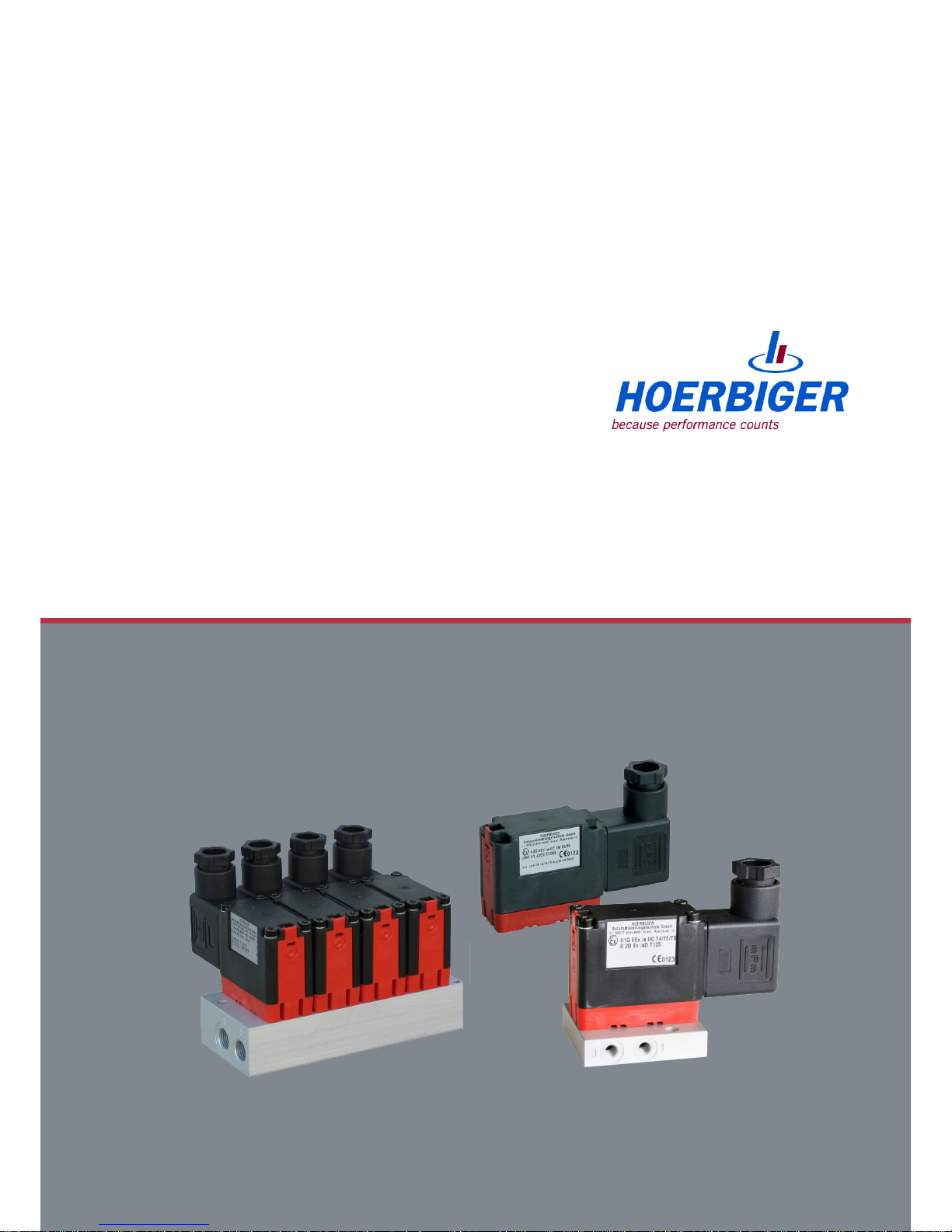
Piezo-pneumatic switch valve
Type P8
Intrinsically safe according to ATEX
Operating instructions
Version 01
ID no.:
3/13/2019
PS09571A

Version: 01
Date: 2018
All rights, errors and changes reserved.
©
Copyright by HOERBIGER 2018
PS09571A
- 2|28 -
Version: 01

Operating instructions
Table of contents
1 Notes about using the operating instructions.............................................................................. 4
1.1 About these instructions ............................................................................................................ 4
1.2 Warnings used .......................................................................................................................... 4
1.3 Symbols................................................................................................................................... 5
1.4 Abbreviations............................................................................................................................ 5
2 Basic safety instructions................................................................................................................ 6
2.1 General notes ........................................................................................................................... 6
2.2 Intended use ............................................................................................................................ 6
2.3 Personnel qualification .............................................................................................................. 8
2.4 Dangers ................................................................................................................................... 9
2.5 Responsibility of the operator................................................................................................... 10
3 Product description ...................................................................................................................... 11
3.1 Function ................................................................................................................................ 11
3.2 Type overview ......................................................................................................................... 11
3.3 Connections ........................................................................................................................... 12
3.4 Technical data........................................................................................................................ 14
3.5 Type plate .............................................................................................................................. 16
4 Assembly and installation............................................................................................................ 17
4.1 Assembly ............................................................................................................................... 17
4.2 Electrical installation............................................................................................................... 19
4.3 Device socket ......................................................................................................................... 19
4.4 Connect control cable to device outlet....................................................................................... 20
5 Start-up.......................................................................................................................................... 22
5.1 Start-up ................................................................................................................................. 22
6 Service ........................................................................................................................................... 23
6.1 Inspection and maintenance plan ............................................................................................. 23
7 Transport and storage................................................................................................................... 24
8 Troubleshooting ............................................................................................................................ 25
9 Decommissioning and disposal................................................................................................... 26
9.1 Decommissioning/dismantling .................................................................................................. 26
9.2 Disposal................................................................................................................................. 26
10 Appendix........................................................................................................................................ 27
10.1 EU design type certificate........................................................................................................ 27
10.2 Product observation................................................................................................................. 27
10.3 Material defects and defects of title.......................................................................................... 27
10.4 Declaration of conformity......................................................................................................... 28
All rights, errors and changes reserved.
©
Copyright by HOERBIGER 2018
PS09571A
- 3|28 -
Version: 01
Operating instructions
Notes about using the operating instructions
1 Notes about using the operating instructions
1.1 About these instructions
These operating instructions describe how to work, operate, and maintain the product
Pneumatic valve P8. They provide important notes for safe and efficient use of the
product.
1. The operating instructions are part of the product. Keep the operating instructions
carefully.
2. Transfer the operating instructions to any subsequent owner or user.
For additional information, contact the manufacturer at the following address:
HOERBIGER Flow Control GmbH
Südliche Römerstraße 15
86972 Altenstadt
Germany
Information on the Internet: www.hoerbiger.com
1.2 Warnings used
Warnings warn about dangers that can occur when handling the product. There are four
danger levels with the following signal words:
Signal word Meaning
DANGER Identifies a danger with high risk that can cause death or
severe injury.
WARNING Identifies a danger with a medium risk that can cause death
or severe injury.
CAUTION Identifies a danger with a low risk that can cause slight or
moderate injury.
NOTICE Identifies a danger that can cause property damage.
All rights, errors and changes reserved.
©
Copyright by HOERBIGER 2018
PS09571A
- 4|28 -
Version: 01
Operating instructions
Notes about using the operating instructions
1.3 Symbols
This symbol indicates useful and important information.
ü This symbol stands for a prerequisite that must be fulfilled before performing an
action.
ð This symbol stands for an individual action to be performed.
1. Numbers indicate several steps to be performed in an action instruction: Step 1
2. Step 2
9 This symbol stands for the intermediate result of an action.
9 This symbol stands for the result of an entire action instruction.
1.4 Abbreviations
Term / Abbreviation Explanation
Ex area Area subject to explosion
GSD Device socket
LED Light Emitting Diode
NG Normally closed
NO Normally open
RF Reset with spring
All rights, errors and changes reserved.
©
Copyright by HOERBIGER 2018
PS09571A
- 5|28 -
Version: 01

Operating instructions
Basic safety instructions
2 Basic safety instructions
2.1 General notes
The product was constructed, manufactured, and tested according to the standards and
safety regulations listed in the current declaration of conformity.
The current declaration of conformity of HOERBIGER Automatisierungstechnik GmbH
and the EU-type examination certificates apply. The CE mark is on the piezo valves’ type
plate.
2.2 Intended use
The piezoelectrically-activated Pneumatic valve P8 serves to control compressed air
activated by the actuators in the standard pneumatic range.
The product is used especially in areas subject to explosion (Ex area according to
EN 1127-1) as well as in non-Ex areas.
Typical areas of application are process technology (turning and positioning drives) and
pneumatic process flow controllers.
1. To ensure perfect, risk-free function and a long life span of the device, follow the
notes in these operating instructions and adhere to the usage conditions and
permissible data according to the data sheet and type plate.
2. The usage planning and operation of the device must be done according to the
recognized rules of technology.
3. Prevent unintentional activations or impermissible interference by taking suitable
measures.
WARNING
Personal injury and property damage possible
■ Only have settings on the valve made by authorized specialized personnel trained by
the manufacturer with suitable tools.
■ Only operate valve in the pressure range specified on the data sheet.
■ Only use valve according to the protection type.
■ Heed the maximum switch-on duration according to the data sheet.
All rights, errors and changes reserved.
©
Copyright by HOERBIGER 2018
PS09571A
- 6|28 -
Version: 01
Operating instructions
Basic safety instructions
WARNING
Use is forbidden in case of:
■ Use of aggressive gases that can damage the valve.
■ Use of pneumatic variables that lie outside the area of application (see Technical
data, page 14).
■ Use of flammable gases that can also explode due to a lack of oxygen.
■ Use as safety valve.
■ Higher pressures than 1.1 bar if the medium is subject to explosion.
■ Use in acid rain or other corrosive atmospheres. Use only after consultation with the
manufacturer.
ð If the device should be operated below the freezing point, dried compressed air must
absolutely be used (pressure dew point 10 K below ambient temperature).
All rights, errors and changes reserved.
©
Copyright by HOERBIGER 2018
PS09571A
- 7|28 -
Version: 01

Operating instructions
Basic safety instructions
2.3 Personnel qualification
Unqualified personnel cannot detect risks and is therefore subject to greater dangers.
1. Only commission qualified personnel with the activities described in these
instructions.
2. Make sure that the personnel adheres to the locally valid regulations and rules for
safe and danger-conscious work.
The following target groups are addressed in these instructions:
Trained person: A trained person is somebody who has been trained extensively by the
operator in his tasks in connection with the safe operation of the valves.
Training is conducted by specialized personnel.
Electrically-qualified person: An electrically-qualified person is somebody who, based on
his specialized training, knowledge, and experience, as well as knowledge of the
applicable regulations, can judge and perform the work with which he is commissioned
and detect possible hazards independently.
Pneumatically-qualified person: A pneumatically-qualified person is somebody who, based
on his specialized training, knowledge, and experience with respect to pneumatic
components and systems as well as knowledge of the applicable regulations, can judge
and perform the work with which he is commissioned and detect possible hazards –
especially with respect to interactions between pneumatic, mechanical, electrical, and
control-technical components – independently.
Activity Authorization
■ Assembly ■ Pneumatically-qualified person
■ Trained person
■ Installation incl. electrical connection
■ Initial start-up
■ Troubleshooting
■ Elimination of faults
■ Taking out of service
■ Electrically-qualified person
■ Trained person with training in the area
of explosion hazards
All rights, errors and changes reserved.
©
Copyright by HOERBIGER 2018
PS09571A
- 8|28 -
Version: 01
Operating instructions
Basic safety instructions
2.4 Dangers
Here you will find information about various types of dangers and damage that can occur
in connection with operation of the product.
Electricity
1. Only have the device connected to the power supply and control lines by an
electrically-qualified person.
2. Only perform installation and maintenance work when the power is disconnected.
Pressure
1. Only have the device assembled by a pneumatically-qualified person.
2. Only install pneumatic components when the compressed air system is
depressurized.
3. During assembly and dismantling, adhere to the recognized rules of technology.
4. During work on pneumatic systems, heed the special safety regulations.
Explosion
1. Do not make any changes to devices that are operated in connection with areas
subject to explosion.
2. Avoid electrostatic charges (danger of explosion with use in Ex areas). These can
arise with friction processes, for example.
3. Use in Ex areas is only permitted with GSD according to DIN EN 175301-803-B.
Use of a GSD with LED in Ex areas is not permitted.
Operation
1. Settings on the valve only by authorized personnel trained by the manufacturer with
suitable tools.
2. Only use the device in industrial applications for compressed air and permissible
gases. Adhere to the working pressure according to the data sheet.
3. The device is only approved for proper or intended use.
4. Do not open the device.
5. Do not remove type designations or seals that do not serve transport protection.
6. Heed the prescribed air purity.
Repair and maintenance
1. Only have repair work on the valve performed by the manufacturer since only the
manufacturer has the equipment for optimal adjustment after repair and can
therefore guarantee perfect function.
2. Do NOT maintain the inner parts of the device.
3. Send the complete valve to the manufacturer for maintenance and service.
All rights, errors and changes reserved.
©
Copyright by HOERBIGER 2018
PS09571A
- 9|28 -
Version: 01

Operating instructions
Basic safety instructions
2.5 Responsibility of the operator
The assumed duties of the operator are:
1. Adherence to operational safety regulations.
2. Adherence to the valid national regulations for occupational safety and explosion
protection.
3. Adherence to the intended use of the valve.
All rights, errors and changes reserved.
©
Copyright by HOERBIGER 2018
PS09571A
- 10|28 -
Version: 01

Operating instructions
Product description
3 Product description
3.1 Function
These product is a piezoelectrically-activated 3/2-way pneumatic valve. Within the valve,
a pneumatically-controlled 3/2-way valve with a piezoelectric pilot valve (piezo chip) is
installed upstream.
With the normally closed version (NG), the flow path from connection 2 to connection 3
is enabled (OFF state) when de-energized. With application of the supply voltage, the
path from connection 1 to connection 2 is enabled (ON state).
Upstream from the piezo valve is a pressure controller with fine filter.
Fig. 1: Schematic circuit diagram
3.2 Type overview
3/2-way poppet valves and single valves, with HOERBIGER-own connection
Type / Order details Valve symbol Activation Note
P8 381RF-NG-S.
P8 385RF-NG-S.-B
1)
Pilot valve
Normally closed
With device outlet,
without connection
plate
P8 381RF-NG-S.-01
P8 385RF-NG-S.-B-01
1)
Individual valve M5
Normally closed
With device outlet
and with connection plate M5
1)
valves with main exhaust air or main and pilot exhaust air and protection type IP65
Accessories: Device outlet type GSD-22; 1, 2 or 4 connection plates and blind plate;
available complete or separately.
All rights, errors and changes reserved.
©
Copyright by HOERBIGER 2018
PS09571A
- 11|28 -
Version: 01

Operating instructions
Product description
3.3 Connections
The P8 valve with large O-ring (see figure) represents a variant with which
building-conditioned ventilation openings are sealed (“cased exhaust air”).
■ Make sure that ventilation is guaranteed with an additional hole in the corresponding
connection block.
The connections shown for the single connection plate are repeated on the connection
plates 2 and 4 times for the battery mounting.
1
Fig. 2: Side view
1 Device outlet type GSD-22
1
2
3
4
5
Fig. 3: Side view
1 Electrical connection (device outlet) 4 Working connection (area
2nd O-ring)
2 Ventilation (optional with large
3rd O-ring possible as cased exhaust
air)
5 Piezoelectric control unit with switch
amplifier
3 Pressure supply (area of inner
O-ring)
All rights, errors and changes reserved.
©
Copyright by HOERBIGER 2018
PS09571A
- 12|28 -
Version: 01

Operating instructions
Product description
Fig. 4: P8 battery mounting on connection plate, 4x
1
2
3
3
5
5
4
Fig. 5: P8 valve can be mounted on connection plate, 1x
1 Screw fastening M3 thread 4 Fastening holes for M4 screw
connections
2 Ventilation (cased exhaust air) 5 Working connection (area of 2nd
O-ring)
3 Pressure supply (area of inner
O-ring)
All rights, errors and changes reserved.
©
Copyright by HOERBIGER 2018
PS09571A
- 13|28 -
Version: 01

Operating instructions
Product description
3.4 Technical data
General technical data
Designation Pneumatic valve P8
Actuation type Piezoelectric pilot valve-controlled
Design Piezo seat valve, not overlap-free
Fastening type Flange
Line connection Flange/threads
Threads M5 with connection plate
Installation position Any
Medium Compressed air and nitrogen
According to ISO 8573-1:2010 (7:3:4)
Flow direction ■ ON: from 1 to 2
■ OFF: from 2 to 3
Storage temperature -40 to +80 °C
Ambient temperature
1)
■ P8 385: -25 to +60 °C
■ P8 381: -10 to +60 °C
Medium temperature
1)
■ P8 385: -25 to +60 °C
■ P8 381: -10 to +60 °C
1)
Use below the freezing point requires dried air (pressure dew point 10 K below ambient
or medium temperature)
Subject to change without notice
Pneumatic characteristics
1)
Nominal pressure (p1) 6 bar
Min. working pressure (p2
min
) 1.5 bar
Max. working pressure (p2
max
) 8 bar
Nominal flow rate (QN) > 50 l/min
1)
Pressure specifications in overpressure
All rights, errors and changes reserved.
©
Copyright by HOERBIGER 2018
PS09571A
- 14|28 -
Version: 01

Operating instructions
Product description
Piezoelectric activation
Approval EU design type certificate
Category,
Ignition protection type
■ P8 385:
– Gas: II 1G Ex ia IIC T4/T5/T6 Ga
■ P8 381:
– Gas: II 2G Ex ia IIC T4/T5/T6 Gb
– Dust: II 2D Ex ia IIIB T125°C Db
1)
HOERBIGER code PT(63) PM(64) PN(61) PN(65) 2)PT(67)
2)
Voltage type DC voltage
Switching voltage
(U“on”)
5.5 to
9 V DC
6 to
16 V DC
7 to
30 V DC
11 to
30 V DC
4.5 to
9 V DC
Switching voltage
(U“off”
max)
3)
1 V DC 1 V DC 1 V DC 1 V DC 1 V DC
Holding current (I“on”) 1 to
19 mA
1.7 to
23 mA
2 to
19 mA
2 to
6.6 mA
1 to
19 mA
Max. current switched
off (I“off”
max)
1)
0.05 mA 0.1 mA 0.22 mA 0.1 mA 0.05 mA
Nominal power (Pn)
1)
5.5 to
171 mW
10 to
368 mW
14 to
571 mW
22 to
198 mW
4.5 to
171 mW
On-time (ED) 100 % ED with maximum 6000 hours constant operation
Protection type (IP) ■ P8 385: IP65 according to DIN EN 60529/A1:2000
■ P8 381: IP43 according to DIN EN 60529/A1:2000
Connection Device plug according to DIN EN 175301-803-B
1)
With use in dust area, it applies that:
■ Max. power loss Pi = 750 mW (T6) / 650 mW (T5) / 550 mW (T4)
■ Max. ambient temperature: 40 °C (T6) / 70 °C (T5) / 80 °C (T4)
2)
Only type series P8 385
3)
For use with cable break detection, check characteristic values for compatibility.
U“off”
max
and I“off”
max
must be ≤ than the values specified above.
Subject to change without notice
All rights, errors and changes reserved.
©
Copyright by HOERBIGER 2018
PS09571A
- 15|28 -
Version: 01

Operating instructions
Product description
Safety technical data according to EU design type certificate
HOERBIGER code PT(63) PM(64) PN(61) PN(65) PT(67)
Voltage (Ui) 9 V 16 V 30 V 30 V 9 V
Current (Ii) Not relevant
External capacity (Ci) 12 nF 12 nF 12 nF 12 nF 12 nF
External inductance (Li) Negligible
Compromising of the valve function possible
■ With mounting outdoors, protect all connections against penetration of humidity.
If necessary, request the current table of compatible, intrinsically safe tools for valves
from HOERBIGER Flow Control GmbH.
3.5 Type plate
II 2G Ex ia IIC T4/T5/T6 Gb
II 2D Ex ia IIIB T125°C Db
Umin./Umax:7-30 VDC
Pmin./max: 1,2bar/ 8bar
Tmin./max: -25°C / 60°C
DMT 01 ATEX E 026 X
0123
Type: P8 385RF-NG-SPM64-B
F-No: PS11048-640A
25/18/ 02
1
2
5
6
7
3
4
8
9
1 Address 6 Item number
2 Ex protection identification 7 Technical data
3 Number of the test center 8 Technical state
4 CE mark 9 Production date (format WW/YY)
5 Type designation
All rights, errors and changes reserved.
©
Copyright by HOERBIGER 2018
PS09571A
- 16|28 -
Version: 01

Operating instructions
Assembly and installation
4 Assembly and installation
4.1 Assembly
DANGER
Mortal danger due to electrical voltage!
■ Switch off current before assembling and dismantling the valve.
WARNING
Danger of crushing due to uncontrolled movement of the machines
Personal injury and/or property damage possible.
■ Before restarting the system, take measures to prevent uncontrolled movement of the
machines.
■ Make sure that nobody is in the danger zone.
WARNING
Personal injury or property damage due to overpressure
Improperly connected or defective pneumatic connections can loosen under pressure and
cause extremely severe injuries.
■ Before assembly and dismantling of valves, switch off compressed air.
■ Make sure that there is neither input nor output pressure on the valves.
■ Only use components that are suitable for the permissible pressure ranges (see Tech-
nical data, page 14).
■ Proceed according to the special country-specific safety regulations.
During installation of the valves in a system/machine in Ex areas, adhere to standards
EN1127-1 and relevant standards.
All rights, errors and changes reserved.
©
Copyright by HOERBIGER 2018
PS09571A
- 17|28 -
Version: 01

Operating instructions
Assembly and installation
WARNING
Personal injury and property damage due to explosion
■ Only install devices within the categories specified on the data sheet.
■ Undertake installation of the intrinsically safe circuits according to the applicable
building regulations (demonstrate knowledge of the builder, protected laying of the
intrinsically safe circuits).
■ Maintain a safety distance of at least 50 mm between intrinsically safe and non
intrinsically safe conductive connection parts.
■ For the interconnection of the devices with the intrinsically safe circuits of the
associated tools, heed the respective maximum values of the field device (valves) and
the associated device in the interest of explosion protection (proof of intrinsic safety).
■ In adverse ambient conditions, protect devices against spray water or dirt according
to the protection type in the current data sheet.
■ For the special conditions of the EU design test certificate, see EU design type
certificate, page 27.
WARNING
Danger due to malfunction
Incorrectly installed valves can cause malfunctions of the entire system and extremely
severe injuries.
■ Create the flange connection according to the instructions.
■ Heed the prescribed installation type and location of the valves (see Technical data,
page 14).
ü The pipelines and flange surfaces are free of contamination.
ü The input pressure is at least 1 bar greater than the maximum required output
pressure.
1. Make sure that the appropriate O-rings or seals are inserted on the valve and the
connection plate.
2. Optionally mount the valve on a connection plate for the direct connection of lines or
on another pneumatic amplifier stage. NOTICE! Tightening torque: P8 385:
60 ±10 Ncm, P8 381: 25 ±5 Ncm
Compromising of the valve function possible
■ Make sure that the ventilation openings are not covered.
■ Protect valve against excessive heat radiation.
■ Protect valve against adverse ambient conditions such as spray water or dirt, in order
to guarantee the protection type according to the data sheet.
All rights, errors and changes reserved.
©
Copyright by HOERBIGER 2018
PS09571A
- 18|28 -
Version: 01

Operating instructions
Assembly and installation
4.2 Electrical installation
DANGER
Mortal danger due to electrical voltage!
■ Only have the device connected to the power supply and control lines by a specialist.
■ Installation may only be done when the device is de-energized.
■ Secure against unintentional switching on.
■ Check electric cables for damage before connecting.
For electrical connections in Ex areas, heed the applicable standards.
DANGER
Mortal danger due to explosion
■ In Ex areas, only use with device outlet according to chapter Device socket,
page 19.
■ Only use the device in areas subject to explosion together with appropriately
approved voltage sources and safety equipment (e.g. separator modules or similar).
■ Have the interconnection assessed by a specialized electrician with knowledge of the
set-up of electrical systems in areas subject to explosion.
■ Lay intrinsically safe lines protected.
■ For the electrical connection, heed the prescribed switching voltage and the
protection type of the cable.
4.3 Device socket
The device outlet corresponds to design B according to industry standard according to
DIN EN 175301-803-B (= type GSD-22).
Use in Ex areas is only permitted with GSD-22 according to DIN EN 175301-803-B.
Use of a GSD with LED in Ex areas is not permitted.
All rights, errors and changes reserved.
©
Copyright by HOERBIGER 2018
PS09571A
- 19|28 -
Version: 01

Operating instructions
Assembly and installation
4.4 Connect control cable to device outlet
1
10
3
5
6
11
2
9
2
10
8
4
7
9
3
The terminal assignments are depicted at the top right of the figure.
1. Loosen the connection locking screw (11).
2. Remove device outlet (10) from the blade contacts of the valve (1). NOTICE! Heed the
installation position of the plug seal (8). The seal must lie correctly and flat.
3. Pull the plug locking screw completely out of the device outlet (10).
4. Pull the connection block (2) completely out of the device outlet with a screwdriver.
5. Turn the screw connection (7) out of the device outlet.
6. Remove the washer (6) and seal (5) from the device outlet.
7. Feed the control cable (4) through the screw connection (7), washer (6), seal (5) into
the device outlet.
8. Adjust the control cable of the seal in diameter so that the cable is tight in the seal.
9. Remove insulation at the end of the control cable. NOTICE! Do not damage the two
wires.
10. Strip the wires with a cable stripper. NOTICE! For the installation, a two-line cable is
sufficient.
11. Clamp both wires of the cable to the screw terminals of the connection block: Wire
“0 Volt” to terminal 1 (3), wire “control voltage” to terminal 2 (9). NOTICE! The
ground clamp is not used. The terminal numbering is engraved in both sides of the
connection block.
12. Place the seal (5), washer (6), and the screw connection (7) to the control cable.
All rights, errors and changes reserved.
©
Copyright by HOERBIGER 2018
PS09571A
- 20|28 -
Version: 01

Operating instructions
Assembly and installation
13. Turn screw connection in the device outlet.
14. Place device outlet with connected cable on the contacts of the valve.
15. Tighten with plug locking screw. NOTICE! Make sure that the plug seal (8) is placed on
the valve over the blade contacts and there is no strain on the cables.
All rights, errors and changes reserved.
©
Copyright by HOERBIGER 2018
PS09571A
- 21|28 -
Version: 01

Operating instructions
Start-up
5 Start-up
5.1 Start-up
With use in environments with flammable gases, heed the Ex directive and other
applicable regulations and the respectively valid local regulations (e.g. flush with inert
gas, avoid adiabatic processes, etc.).
WARNING
Personal injury and property damage possible
■ Only have the start-up done by people who have sufficient knowledge and experience
with respect to compressed air systems and the machine/system to be started up.
■ Before operation with combustible gases, consult the manufacturer.
■ Heed additional measures according to the local set-up provisions (e.g. incorporation
into the repeated pressure test).
■ For start-up of the valves, adhere to the following sequence of steps.
ü The power supply is switched off.
ü There is neither input nor output pressure present.
1. Check proper mounting.
2. Open compressed air supply.
WARNING
Danger of crushing due to uncontrolled movement of the machines
Personal injury and/or property damage possible.
■ Before restarting the system, take measures to prevent uncontrolled movement of the
machines.
■ Make sure that nobody is in the danger zone.
3. Switch on electric signal control.
All rights, errors and changes reserved.
©
Copyright by HOERBIGER 2018
PS09571A
- 22|28 -
Version: 01

Operating instructions
Service
6 Service
The transmission behavior of the devices is also stable across long time periods. Regular
adjustment or similar is thus not required. There should also not be any maintenance
work required.
Compromising of the valve function due to incorrect cleaning
■ Do not use cleansers that contain solvents for cleaning work.
■ No solvents or solids may penetrate the openings for ventilation and manual
activation.
WARNING
Personal injury and property damage due to improper servicing
Malfunctions can results.
■ In case of fault, do NOT service the device.
■ In case of fault, shut the device down immediately.
■ Remove the complete valve and send it to the manufacturer's local agent for
servicing.
6.1 Inspection and maintenance plan
Work to be performed ir d w ¼ y y oh
■ Check pneumatic connections for leaks
X
■ Check electrical cable for cracks, kinks, and
damage to the cable insulation.
■ Replaced damaged lines.
X
■ Check type plates to ensure they are present,
visible, legible, and complete; replace if
necessary
1
■ Check fastening screws to ensure they are
tight, tighten if necessary
X
Legend: ir= if required, d = daily, w = weekly , ¼ = quarterly, y = annually, oh = operat-
ing hours
All rights, errors and changes reserved.
©
Copyright by HOERBIGER 2018
PS09571A
- 23|28 -
Version: 01

Operating instructions
Transport and storage
7 Transport and storage
1. Store the product in level, dry rooms that are free of dust and vibrations.
2. In case of longer unpackaged storage, seal all pneumatic connections of the valve
with tape that can be removed without leaving residues.
For more information, see Technical data, page 14.
All rights, errors and changes reserved.
©
Copyright by HOERBIGER 2018
PS09571A
- 24|28 -
Version: 01

Operating instructions
Troubleshooting
8 Troubleshooting
1. Customers and third parties should not make any changes to or perform any
troubleshooting on the device.
2. Send the defective product to the manufacturer or its local representative for
servicing.
All rights, errors and changes reserved.
©
Copyright by HOERBIGER 2018
PS09571A
- 25|28 -
Version: 01

Operating instructions
Decommissioning and disposal
9 Decommissioning and disposal
9.1 Decommissioning/dismantling
WARNING
Risk of injury due to pressure
■ Do not perform any work on the valve when it is pressurized.
ü The power supply is switched off.
ü There is no input or output pressure.
ü The machines/systems (e.g. actuators) have been moved into a safe switch state
(control positions).
ð Dismantle.
9.2 Disposal
The disposal of the packaging and used parts is the customer’s responsibility.
ð Dispose of the product according to the local regulations at approved collection
points or have removed by approved disposal companies.
All rights, errors and changes reserved.
©
Copyright by HOERBIGER 2018
PS09571A
- 26|28 -
Version: 01

Operating instructions
Appendix
10 Appendix
10.1 EU design type certificate
We will be glad to send the customer the EU design type certificate on request.
The EU design type certificate applies only for the electrical examination of the basic P8
valve devices.
The approval according to EU design type certificate is only provided with device outlets
according to DIN EN 175301-803, design B according to industry standard.
10.2 Product observation
Our goal is continuous enhancement of our products and close cooperation with the
customer. Please tell us about faults or problems with the valve.
10.3 Material defects and defects of title
These operating instructions and technical details with respect to the specifications and
figures in these operating instructions are subject to change without notice.
The company HOERBIGER Flow Control GmbH makes no quality or durability guarantees,
and also no guarantees about suitability for a particular purpose. These must be agreed
upon expressly in writing. Public statements, promotions, and advertising co not
constitute quality specifications for the product.
The operator’s claims relating to material defects and defects of title assume that he
presses this claim in writing immediately, at the latest within two working days.
HOERBIGER Flow Control GmbH is in no case responsible for damage to the product
itself or consequential damages caused by the product that are caused by improper
handling of the product.
Insofar as HOERBIGER Flow Control GmbH is responsible for a defect, HOERBIGER Flow
Control GmbH will, at its option, provide rectification of substitute performance.
Liability of HOERBIGER Flow Control GmbH – regardless of the legal justification – exists
only in case of intention or gross negligence, negligent injury of life, body, health for
defects that were fraudulently concealed or whose absence was guaranteed expressly in
writing. Furthermore, according to the product liability law for personal injury or property
damage to privately used objects.
In case of negligent injury of essential contract duties, HOERBIGER Flow Control GmbH
is also liable, also in case of slight negligence, however limited to the contract-typical,
foreseeable damages. Additional claims are excluded.
In case individual regulations of these operating instructions, the applicable legal
regulations or other instructions of HOERBIGER Flow Control GmbH are disregarded,
material defects and defects of title are terminated.
All rights, errors and changes reserved.
©
Copyright by HOERBIGER 2018
PS09571A
- 27|28 -
Version: 01

Operating instructions
Appendix
In particular, HOERBIGER Flow Control GmbH is not responsible for failures or faults
that are caused by modifications by the customer or other persons. In such cases, the
repair costs due will be invoiced. These will also be invoiced for the checking of the
device if no fault could be found on the device.
There are no claims to the availability of previous versions and to the ability to refit
devices delivered to the respective current series state.
10.4 Declaration of conformity
The current declaration of conformity is included in the scope of delivery and it can be
found in the download area on the company's website:
http://www.hoerbiger.com/
All rights, errors and changes reserved.
©
Copyright by HOERBIGER 2018
PS09571A
- 28|28 -
Version: 01
 Loading...