

HOERBIGER ORIGA SYSTEM PLUS OSP-P, OSP-P 10, OSP-P 16, OSP-P 25, OSP-P 32 Operating Instructions Manual
...
ORIGA SYSTEM PLUS
Operating Instructions
Modular Pneumatic Linear Drive System OSP-P

Modular Pneumatic Linear Drive System OSP-P
Content
Chapter Page
1 Foreword to the Operating Instructions 3
2 Safety 4
3 Warranty 5
4 Transport and Assembly 6
5 After sales service 6
6 Technical description of the basic cylinder OSP-P 7
6.1 Technical data .................................................................................................................................. 7
6.2 Design and Function ...................................................................................................................... 7
7 Technical Description of Clean Room Cylinder OSP-P 9
7.1 Technical data .................................................................................................................................. 9
7.2 Design and function principle of clean room cylinders ........................................................ 9
8 Installation in machine or plant 10
8.1 Preparations.................................................................................................................................... 10
8.2 Installation of OSP-P ..................................................................................................................... 10
8.3 Connection diagram..................................................................................................................... 11
8.4 Accessories ..................................................................................................................................... 11
9 Commissioning 11
9.1 Commissioning of an OSP-P cylinder ...................................................................................... 11
9.2 Commissioning of a Complete Plant ........................................................................................ 12
9.3 Re-commissioning after long periods without operation ................................................... 12
10 Removal from plant 12
11 Service / Maintenance OSP-P 13
11.1 Maintenance intervals .................................................................................................................. 13
11.2 Cleaning .......................................................................................................................................... 13
11.3 Dismantle, clean, repair and assemble cylinder OSP-P ....................................................... 14
12 Trouble shooting 22
12.1 List of faults...................................................................................................................................... 22
12.2 Cleaning the Inner Sealing Band .............................................................................................. 23
13 Removal / Disposal 23
14 Manufacturer`s Declaration 24
15 Spare Parts Lists 25
15.1 Replacement Parts (not OSP-P Clean Room Cylinder) ......................................................... 26
15.2 Service Kits (not OSP-P Clean Room Cylinder) ...................................................................... 26
15.3 Replacement Parts (not OSP-P Clean Room Cylinder) ......................................................... 26
15.4 Lubrication ...................................................................................................................................... 27
2
1 Foreword to the Operating Instructions
The purpose of these Operating Instructions is to assist you in familiarising yourself with the OSP-P
and to make use of the functions it has been designed for.
The Operating Instructions contain important advice so that you can use the OSP-P safely, reliably
and economically. Observance of these Operating Instructions will help you to avoid danger, reduce
repair costs and downtime as well as to increase reliability and the service life of the OSP-P.
These Operating Instructions need to be read and applied by all persons working with the OSP-P,
including:
• operating the unit, including setup work, trouble shooting during the work sequence, removal of
production waste, servicing, handling as well as removing waste of hazardous materials (operating
and auxiliary materials);
• maintenance (preventive maintenance, inspection, repairs)
In addition to the Operating Instructions and the mandatory regulations for accident prevention and
environmental protection applicable in the user country and at the location of deployment , the
standard technical rules and regulations for safe and professional work shall also be observed.
User’s Responsibilities
The following is assumed to be the operator’s/organisation’s responsibility:
• compliance with EN 89/655 and the national applications
• compliance with the applicable national regulations for safety at work
• authorized use of OSP-P
• correct applications of these operating instructions.
EN
Commissioning of the OSP-P is forbidden until it has beed established that the machine/
plant in which it is to be installed complies with the requirements of the EC Machines
Directives.
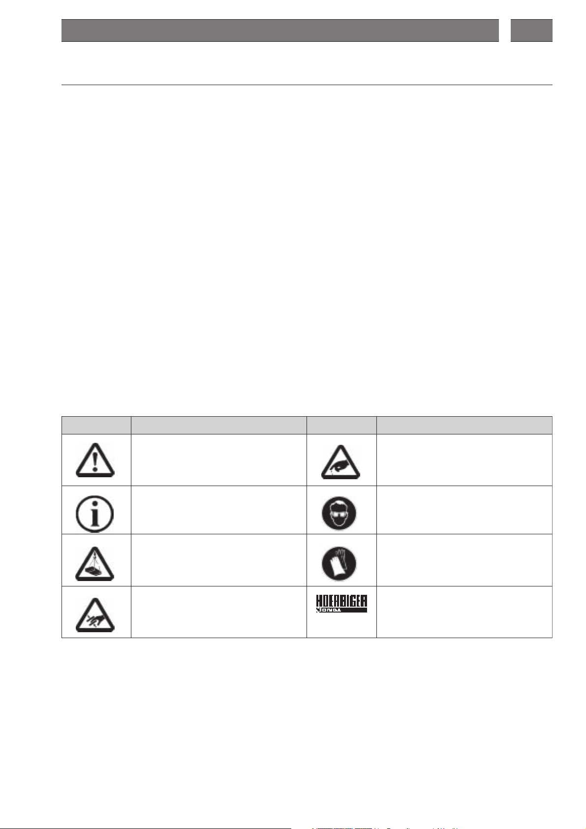
Explanation of Symbols and Notes
Notes which are highlighted by these symbols help to prevent injury to personnel. Please ensure
that all users understand them.
lobmyS lobmySfonoitanalpxE lobmyS lobmySfonoitanalpxE
noitnettA: oteruliaffidesusilobmyssihT
,snoitcurtsnignitarepohtiwylluferacylpmoc
lanosrepotdaelnac.cte,secneuqesgnitarepo
.tnalpehtotegamadrostnediccalataf,seirujni
noitamrofnIotsetondnaspitroflobmyS:
tneverpotplehotdnaenihcamfoesuetatilicaf
.egamad
noitnettAdaolgnillaF:etoN: sevolgytefasraeW
noitnettAgnihsurcforegnaD:etoN: yrosseccaelbaliavA
noitnettA: .ctesregnifotstucforegnaD
etoN: sessalgytefasraeW
Copyright
Copyright 2005
They must not be copied in full or in part, distributed or used in an unauthorized manner for compe-
titive purposes or passed on to others. Contravention may lead to legal action.
HOERBIGER-ORIGA GmbHHOERBIGER-ORIGA GmbH
HOERBIGER-ORIGA GmbH retains the copyright in these operating instructions.
HOERBIGER-ORIGA GmbHHOERBIGER-ORIGA GmbH
3

Modular Pneumatic Linear Drive System OSP-P
The Type Lable
You will find the type label on the OSP-P under the red cover strip near the company name.
Ø 10:
Stroke
Ø 16-80:
2 Safety
Order No.
Type Designation
Unit of Measurement
Europe [mm]
Customer Order No.
Diameter
Variant Code
Delivery Date
Repair No.
Stroke
Production Order No.
Produkt Monitoring
Our goal is to supply safe, state-of the-art products. Therefore we monitor our products constantly
after delivery. Please inform us immediately of any recurring malfunctions or problems with the
OSP-P.
Authorized Use
The operating safety of the OSP-P is only guaranteed if it is used in authorized applications.
Authorized applications of the OSP-P are:
• To move loads.
• To exert force.
The OSP-P is driven by compressed air.
The following should also be observed:
• Conditions laid down in the order confirmation.
• The Operating Instructions.
• Cataloque OSP-P.
If the OSP-P is used in any other way, this would constitute an „
This could result in property damage or personal injury for which we cannot be held responsible.
The risk is borne by the user alone.
UnauthorizUnauthoriz
Unauthoriz
UnauthorizUnauthoriz
ed Useed Use
ed Use“.
ed Useed Use
Personnel
The operator of the complete plant must ensure that work on the OSP-P is carried out only by authorized and qualified personnel. Authorized personnel are trained engineers of the operator, the manufacturer and the service partner.
Safety-Conscious Working Practices
The contents of these Operating Instructions, particularly the chapter on “Safety Instructions” must
be duly observed under all circumstances.
Before commencing work, all personnel assigned to work with the OSP-P must have read and thoroughly understood the Operating Instructions - and the chapter on Safety in particular. Doing so
while at work is too late !! This also applies in particular to personnel working occasionally on the
OSP-P, e.g., during set-up and maintenance.
At appropriate intervals, check the safety-awareness of the personnel at work with due observance
of the Operating Instructions.
The following are not permitted:
• Unauthorized modifications of the OSP-P.
• Working methods which impair the safety of the OSP-P.
Observe at the OSP-P :
• All attached safety instructions.
• Markings for compressed air connections.
Maintain these instructions in a fully legible condition.
Observe also the manufacturer’s instructions on lubricants, solvents and cleaning agents.
4

EN
Conversions and alterations
The linear drives shall not be modified in its construction and safety aspects, without the prior written approval of HOERBIGER-ORIGA GmbH. Any such modifications carried out without approval will
rule out all liability on the part of HOERBIGER-ORIGA GmbH.
In principle, no safety and protection devices/equipment shall be dismantled or put out of operation.
When installing special attachments, the assembly regulations of the manufacturer shall be obser-
ved as required.
The following regulatory instruments must be observed as a matter of course:
• Relevant rules and regulations for accident prevention.
• Generally recognised safety regulations.
• EU-Directives and
• country-specific provisions.
Dangers after shutting down the OSP-P or the whole plant
Even after venting the whole plant there can still pressure in the cylinder. This may result in uncontrolled movements of the piston.
Reversal of Movement in an Emergency
See the operating instructions for the whole plant.
Spare parts
The use of original spare parts and accessories authorised by the manufacturer is an important
aspect for your safety. The use of other parts may change the characteristics of the OSP-P.
We accept no liability for any consequences resulting from the use of such parts.
3 Warranty
We reserve the right to make alterations to these Operating Instructions as well as to technical
details with reference to data and illustrations as contained in these Operating Instructions.
HOERBIGER-ORIGA GmbH issues no quality and durability guarantees or any guarantees for the
suitability for certain purposes unless these are expressly agreed in writing.
Public statements, statements of quality or advertising are not statements of characteristics.
If the user wants to make a claim under the warranty, he needs to notify the fault immediately and
describe it precisely in his statement of complaint. Under no circumstances is
Hoerbiger-ORIGA GmbH responsible for damage to the product itself or for consequential damage
caused by the product, as caused by incorrect and faulty handling of the product. Insofar as
HOERBIGER-ORIGA GmbH is responsible for a fault, HOERBIGER-ORIGA GmbH may, at its discretion,
either repair/modify the product or replace the item with a new one.
All OSP-P are provided with an identification plate within the framework of ISO 9000, that is
attached to an OSP-P. This identification plate shall not be removed or destroyed in any way.
A liability of Messrs HOERBIGER-ORIGA GmbH – irrespective of the legal reason – exists only in the
event of intentional or gross negligence, culpable injury to life, body, health, in the event of deficiencies with malicious intent of deception or faults the absence of which has been expressly guaranteed.
Furthermore, the company is liable to the extent stipulated by the product liability law regarding
personal injury or material damage on objects used privately. In the event of culpable violation of
essential contractual obligations, HOERBIGER-ORIGA GmbH is liable also in the case of minor negligence, however, limited to the damage that could be foreseen under the contract.
Any other claims are ruled out.
No warranty shall apply in the event of non-observance of these Operating Instructions, the relevant
legal provisions as well as further instructions of the supplier.
In particular, we are not responsible for stoppages caused by modifications by the customer or other
persons. In such cases, we charge the normal repair costs. These are also charged for an inspection
of the equipment where no fault can be found on the equipment.
This regulation also applies during the warranty period.
Users have no rights regarding the supply of previous equipment versions or regarding the upgra-
ding of equipment to the current version.
5
Modular Pneumatic Linear Drive System OSP-P
4 Transport and Assembly
4.1 Transport
To avoid damages during transportation and storage the linear drives have to be transported as
described below and to be protected against dirt, humidity and violence by means of appropriate
protective packing.
Danger caused by falling load
Incorrect transport and assembly of the OSP-P can:
• Endanger human life.
• Result in material damage.
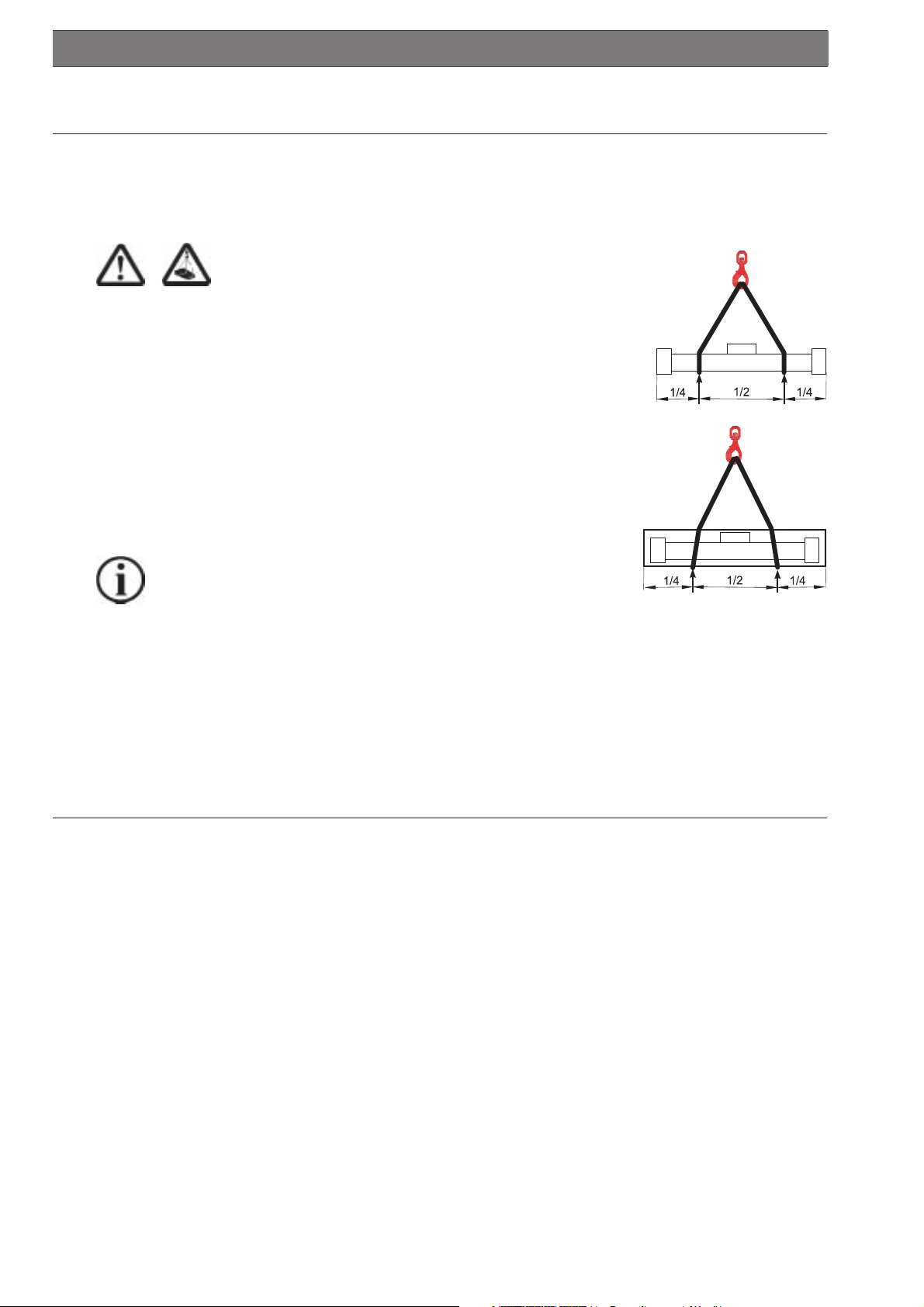
Transport of OSP-P:
Avoid deflection of the OSP-P!
• If necessary, carry long and thin cylinders with several persons.
Transport of the packaged OSP-E with a crane or a forked-lift
truck. (see illustrations on the right side)
• Apply ropes of appropriate length with a load application ratio as
shown or position the fork-lift truck at the appropriate points.
• In the case of very long cylinders always use appropriate harness
such as equalizers or fixtures in order to avoid deflection of the
cylinders.
unpacked
packed
Information
Transport damage and missing parts are to be reported immediately and in writing to the
transport company or to HOERBIGER-ORIGA GmbH or to the delivery company.
4.2 Storage
Where storage or interim storage is involved, you must observe the following:
• Dry, dust- and vibration-free storage.
• On a
• Outdoors under a suitable covering.
You must avoid deflection (bending) of the OSP-P !
flat surfaceflat surface
flat surface.
flat surfaceflat surface
5 After sales service
Spare parts and after sales service addresses
Refer to the last page of these Operating Instructions.
Spare parts list
For the purposes of preventive maintenance for the linear drives, we offer seal kit sets, service
packages and spare parts (refer to Chapter 15 page 25).
Please observe our homepage
wwwwww
www
wwwwww
.origa-servic.origa-servic
.origa-servic
.origa-servic.origa-servic
e.ce.c
e.c
e.ce.c
omom
om
omom
6
6 Technical description of the basic cylinder OSP-P
6.1 Technical data
For further detailed information on
• dimensions
• space requirements, mounting dimensions
• forces and loads
• speeds and cushioning energy
• weights
and additional data see catalogue OSP-P.
EN
Operating pressure range: p
Speed: > 0,005 m/s (Ø10 > 0,12 m/s)
Compressed air requirements: Free of water and dirt. Additional lubrication with oil mist is not
Noise level: The sound emission values (sound level) of the OSP-P are
Installation: In any position
Temperature range: From -10° C to 80° C.
The right to introduce technical modifications is reserved.
Information
With oil mist lubrication, the cylinder must be supplied with oil constantly while in operation.
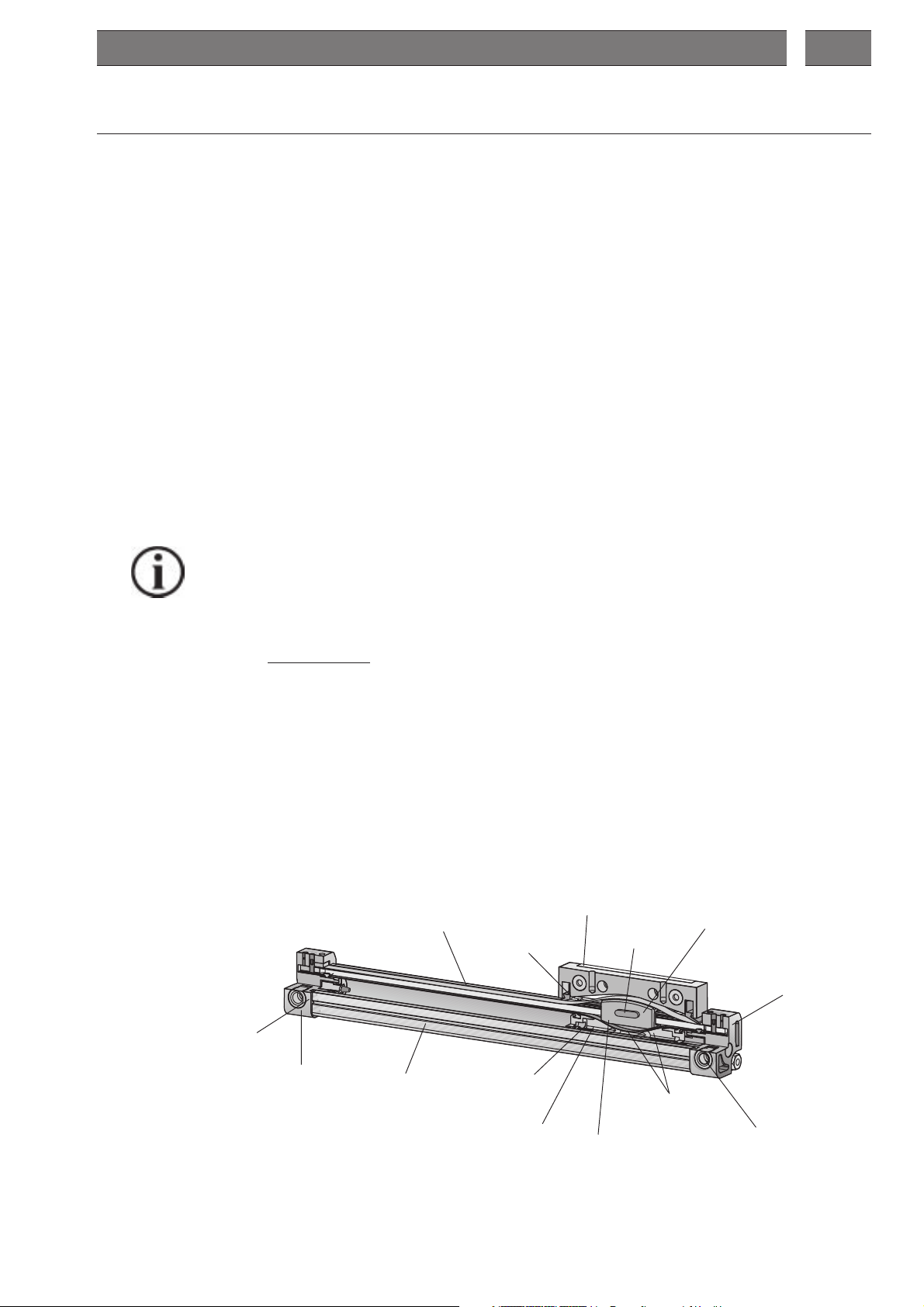
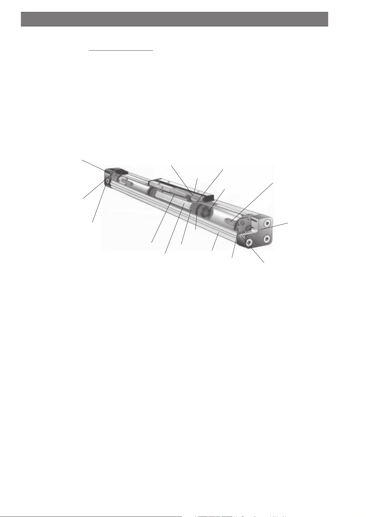
6.2 Design and Function
6.2.1 Design Features Cylinder Ø 10
• The OSP-P is a pneumatic working cylinder without piston rod.
• The longitudinal slot in the cylinder is sealed and protected by stainless steel bands.
• The piston consists of piston yoke, support rings, sealing bands, piston seals, bearing strips and
magnets on the inside.
On the outside it includes the carrier and the wipers.
• The load is mounted on a carrier.
• The air supply (from the air connection) goes through the cushion spigot into the cylinder barrel.
• The end cushioning is made via integrated rubber buffer. It cannot be adjusted.
• The cylinder has permanent grease lubrication. Oil lubrications require a constant supply of oil.
• For speeds < 0,2 m/s we recommend our slow speed grease.
= 8 bar.
max
necessary.
below 70 dB(A).
Carrier (39)
Bearing stripl (28)
Magnets firmly
bonded with
piston yoke
Inner band sealing (17)
(I-Band)
Piston yoke (27)
End cap right
with integrated
rubber buffer
(37)
Air connection
Air connection
End cap left
with integrated
rubber buffer
(35)
Outer sealing band (11)
(O-Band)
Cylinder barrel (1)
Wiper (8)
Piston seal (24)
Support ring (25)
NOTE:
Numbers in brackets refer to parts list item and exploded view drawing of the spare parts list
(from page 25).
7
Modular Pneumatic Linear Drive System OSP-P
6.2.2 Design Features Cylinder Ø 16 to Ø 80
• The OSP-P is a pneumatic working cylinder without piston rod.
• The longitudinal slot in the cylinder is sealed and protected by stainless steel bands.
• The piston consists of piston yoke, support rings, piston seals, cushion seals, slide shoes and
magnet set on the inside.
On the outside it includes the carrier and the wipers.
• The load is directly mounted on a piston yoke.
• The air supply (from the air connection) goes through the cushion spigot into the cylinder barrel.
• End cushioning is created by a compression space around the cushion spigot between the
cushion seal and the cover, at the end of each cylinder barrel. With the help of a needle valve it
can be adjusted at each cylinder end.
• The cylinder has permanent grease lubrication. Oil lubrications require a constant supply of oil.
• For speeds < 0,2 m/s we recommend our slow speed grease.
End cap left (35)
Needle valve to adjust end
cushioning
Air connection
Note:
Outer sealing band (11)
(A-Band)
Slide shoe (28)
Piston yoke(27)
Cover (9)
Piston
seal (24)
Support ring (25)
Cylinder barrel (1)
Needle valve to adjust end
cushioning
Numbers in brackets refer to parts list item and exploded view drawing of the spare parts list
(page 25).
6.2.3 Functional Principle and Application Cylinder Ø 10 to Ø 80
• The piston is moved by compressed air in the cylinder. In the typical operating mode, both sides
of the cylinder are initially charged with compressed air and then the side towards which one
wants the cylinder to move is vented. For special applications it is possible to use different types
of control if other parameters are also taken into consideration.
• The piston yoke holds the sealing bands in grooves. The force is transmitted directly to the
outside.
• The unit is fitted with the help of threads on its front face. Cover mountings can be supplied as
accessories.
• For long cylinders, additional mid-section supports should be used (also available as accessories). For further details please refer to the catalogue.
Inner band sealing (17)
(I-Band)
Cushion spigot (20)
Cushion seal (23)
End cap right (35)
Air connection
8
7 Technical Description of Clean Room Cylinder OSP-P
7.1 Technical data
All other detailed information comply with the OSP-P standard cylinder. For additional details please
refer to the
cc
atat
alogue OSPalogue OSP
c
at
alogue OSP
cc
atat
alogue OSPalogue OSP
-P-P
-P.
-P-P
EN
Piston diameter: 16, 25 and 32
Clean room classClean room class
Clean room class in accordance with DIN EN ISO 14644-1 with vacuum suction flow of 4 m
Clean room classClean room class
ISO-Class 4 at v
ISO-Class 5 at v
average
average
Requirements to compressed air: free of water and dirt. Additional oil mist lubrication not
required.
Installation: in any position
Temperature range: -10° C to 80° C
Max. stroke: 1200 mm, longer strokes on request
The right to introduce technical modifications is reserved.
IMPORTANT:
Lubrication: permanent grease lubrication
(additional oil mist lubrication not recommended)
Option: slow speed grease
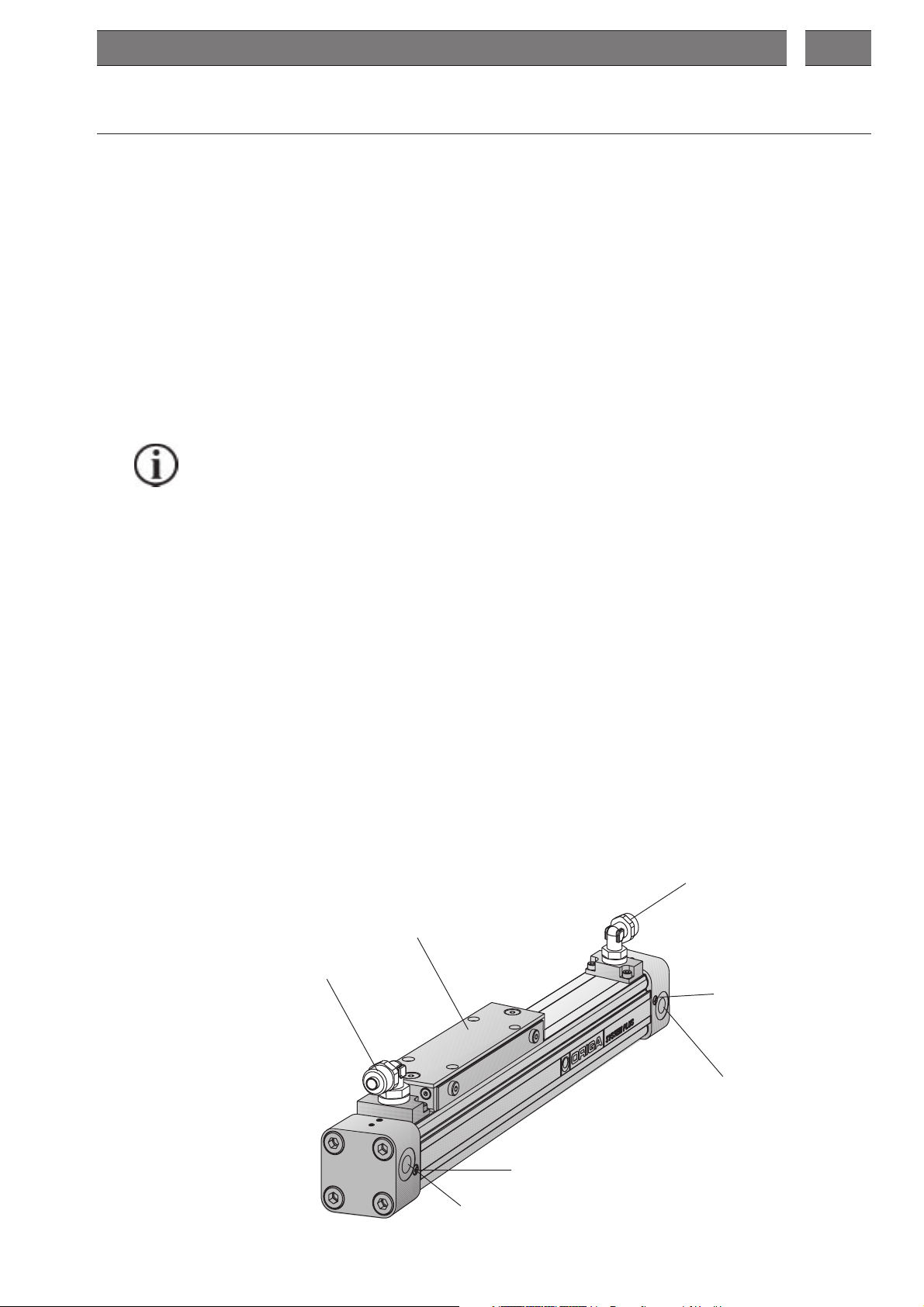
7.2 Design and function principle of clean room cylinders
• The rodless clean room cylinder OSP-P is moved by compressed air. In the typical operating
mode, both sides of the cylinder are initially charged with compressed air and then the side
towards which one wants the cylinder to move is vented. For special applications it is possible
to use different types of control if other parameters are also taken into account.
• The unit is fitted with the help of threads on its front face. Cover mountings can be supplied as
original accessories.
• The load is directly mounted on the piston.
• The longitudinal slot in the cylinder is sealed and protected by stainless steel bands.
• The difference between the clean room cylinder OSP-P and the rodless standard cylinder OSP-P
is that a vacuum is created between the internal and the external steel band.
To generate the vacuum there are two air connections where a vacuum pump can be connected.
To ensure proper extraction of the particle emission a vacuum suction flow of 4 m³/h is recommended.
• End cushioning is infinitely variable (see cushioning diagram in catalogue OSP-P).
• For speed ranges < 0.2 m/s we recommend our slow speed grease.
• All fixing screws are of stainless material.
= 0,14 m/s
= 0,5 m/s
3
/h
Air connection
vacuum pump
Air connection
vacuum pump
Piston yoke
Needle valve to adjust end
cushioning
Air connection cylinder
Needle valve to adjust end
cushioning
Air connection cylinder
9
 Loading...