

Page 1
PL
INSTRUKCJA UŻYTKOWNIKA
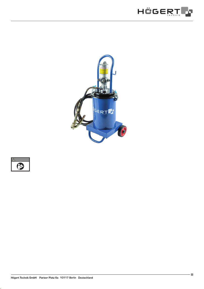
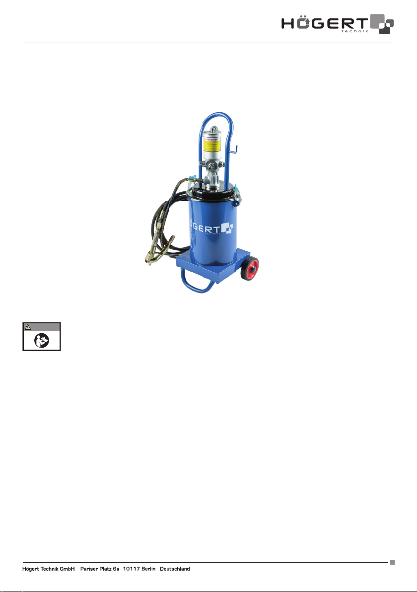
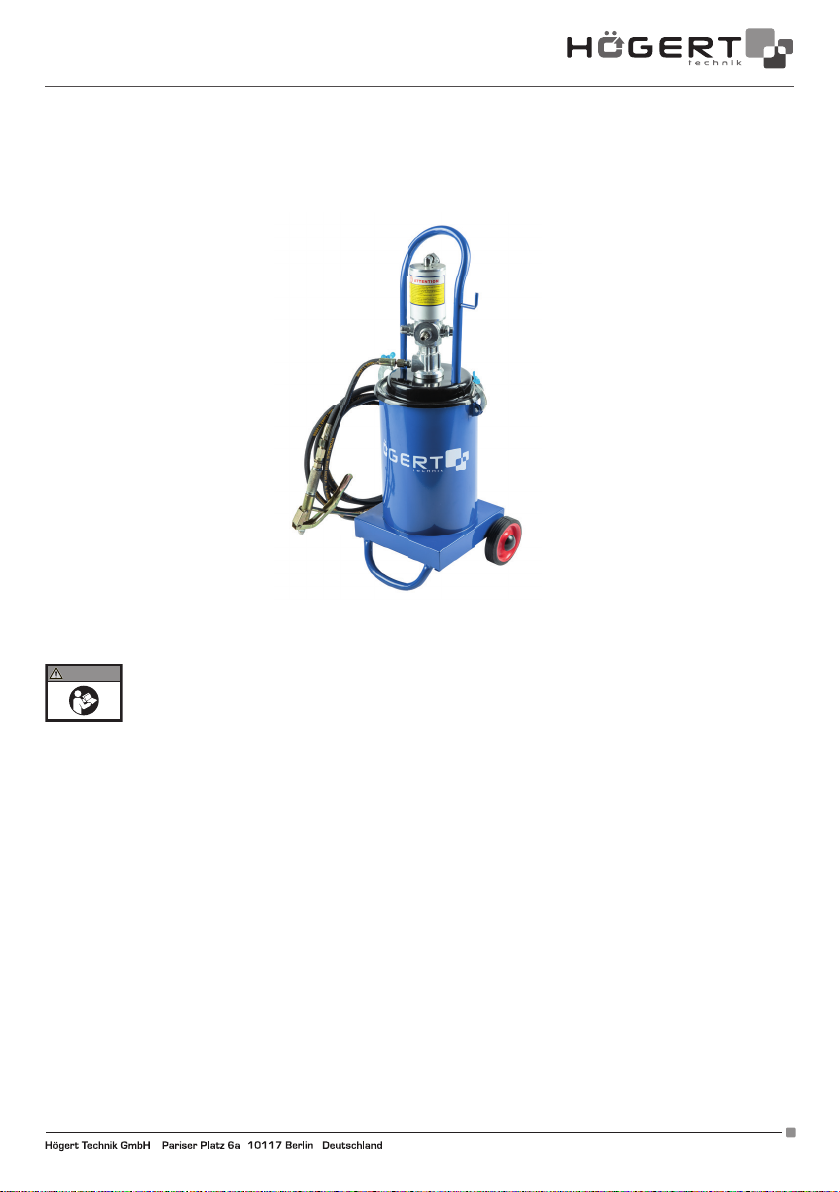
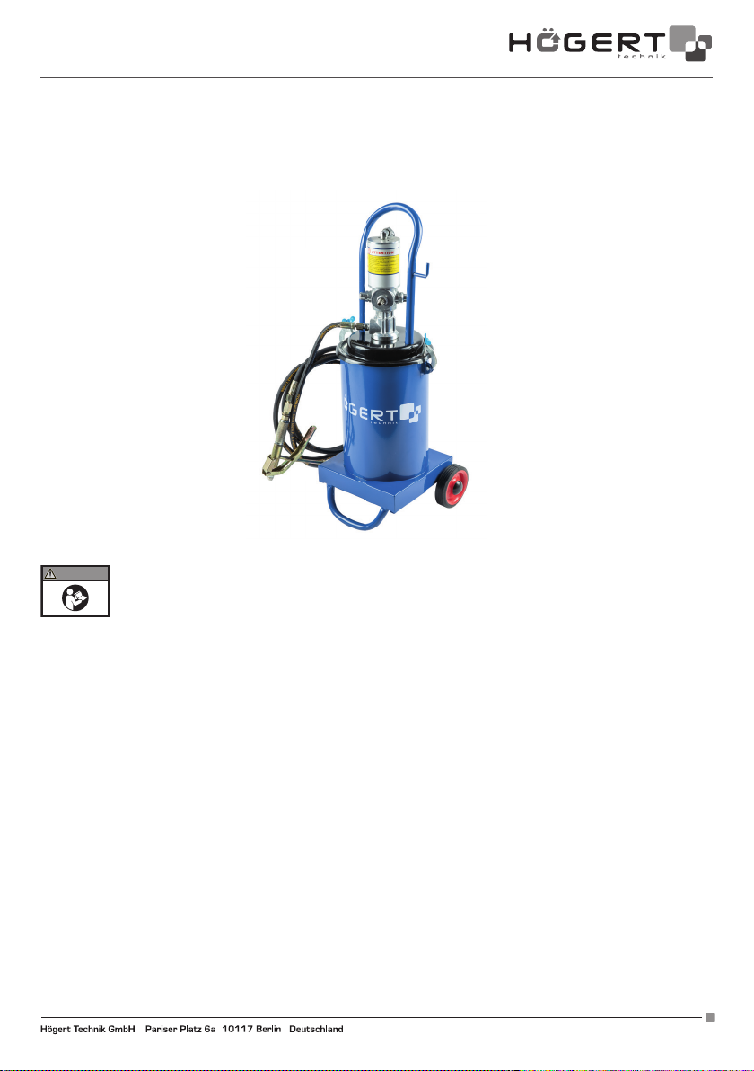
SMAROWNICA PNEUMATYCZNA 12 L HT4R795
Dziękujemy za zakup naszego produktu. Urządzenie to, wyprodukowane według wysokich standardów, jeśli będzie używane
zgodnie z niniejszymi instrukcjami i właściwie konserwowane, zapewni lata bezawaryjnej pracy.
WARNING
W BEZPIECZNYM MIEJSCU NA PRZYSZŁY UŻYTEK.
Smarownica pneumatyczna HT4R795 wykorzystuje sprężone powietrze jako napęd. Cechuje się niezawodnością, niskim zużyciem
powietrza, wysokim ciśnieniem roboczym, wygodą użytkowania, wysoką wydajnością, niskim nakładem pracy, możliwością wtrysku
smaru o dużej lepkości. Zastosowanie w motoryzacji, rolnictwie, przemyśle.
GŁÓWNE PARAMETRY
Stosunek ciśnień: 50 : 1
Sprężone powietrze: 6-8 Bar / 87-116 PSI
Średnica cylindra: 70 mm
Skok cylindra: 35 mm
Wydajność: 0,85 l / min
Ciśnienie transmisji: 300-400 Bar / 4350-5800 PSI
Pojemność zbiornika smaru: 12 kg
Waga urządzenia: 16,5 kg
Wymiary zewnętrzne: 840 x 360 x 320 mm
DZIAŁANIA I BUDOWA SPRZĘTU
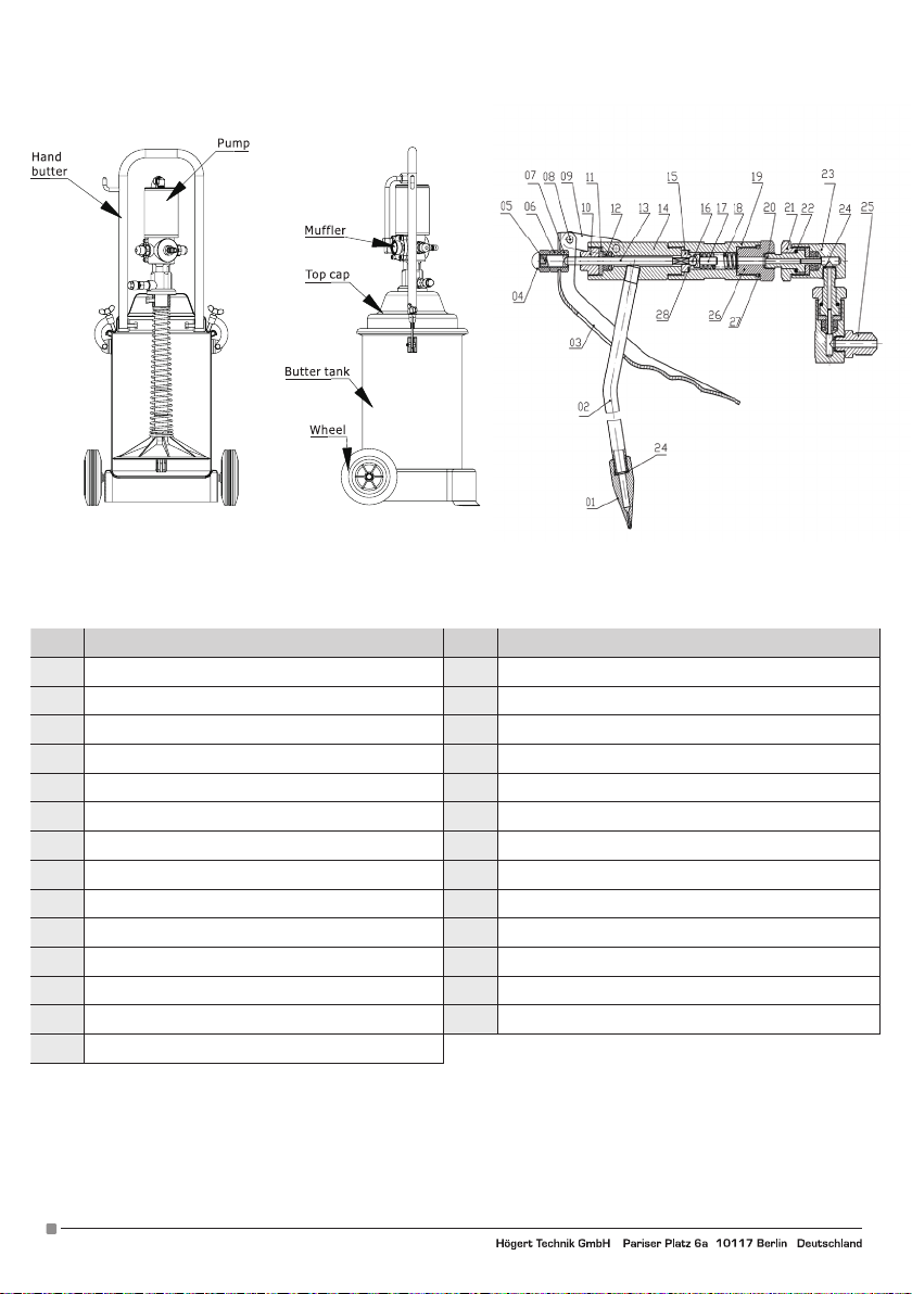
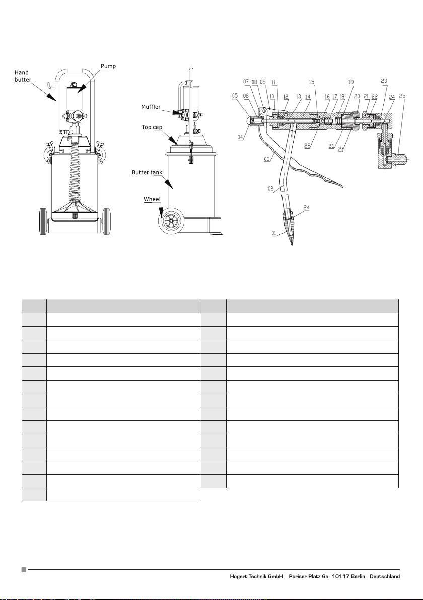
Smarownica pneumatyczna składa się z pompy wtryskowej smaru, pistoletu do wtryskiwania smaru, rury wysokociśnieniowej, szybkozłączki, pojemnika smaru.
Pompa wtryskowa smaru jest połączona z górną pompą powietrza i dolną pompą tłokową. Pompa powietrza jest pompą napędową;
sprężone powietrze jest wykorzystywane do napędzania tłokowej pompy w ruchu posuwisto-zwrotnym w celu wytworzenia ciśnienia
smaru. Z uwagi na fakt, że dopuszczalna powierzchnia tłoka cylindra jest większa niż powierzchnia cylindra tłoka pompy tłokowej,
ciśnienie można znacznie zwiększyć, prawidłowy współczynnik powierzchni wynosi 50 : 1. Przy sprężonym powietrzu 6 Bar, wyjściowe
ciśnienie smaru może osiągnąć 300 Bar (pomijając straty).
Adres producenta/ Adresse des Herstellers/ Manufacturer’s Address/ Адрес производителя
GTV Poland Sp. z o.o. Sp. k., ul. Przejazdowa 21, 05-800 Pruszków. www.hoegert.com
WAŻNE: NALEŻY UWAŻNIE ZAPOZNAĆ SIĘ Z TREŚCIĄ NINIEJSZEJ INSTRUKCJI. ZWRÓCIĆ UWAGĘ NA
WYMAGANIA DOTYCZĄCE BEZPIECZEŃSTWA WYKONYWANYCH PRAC. OSTRZEŻENIA I UWAGI: Z PRODUKTU
NALEŻY KORZYSTAĆ W SPOSÓB PRAWIDŁOWY, Z ZACHOWANIEM OSTROŻNOŚCI ORAZ ZGODNIE Z JEGO
PRZEZNACZENIEM. NIEZASTOSOWANIE SIĘ DO POWYŻSZEGO MOŻE BYĆ PRZYCZYNĄ USZKODZENIA
MIENIA I/LUB CIAŁA ORAZ SPOWODUJE UTRATĘ GWARANCJI. INSTRUKCJĘ NALEŻY PRZECHOWYWAĆ
1
Page 2
No. Nazwa No. Opis
1 Końcówka 15 Uchwyt zaworu
2 Króciec 16 Kulka stalowa 6 mm
3 Uchwyt 17 Rurka smarownicza
4 Nakrętka 18 Sprężyna
5 Śruba regulacyjna 19 Podajnik smaru
6 Śruba mocująca 20 Rdzeń osi
7 Śruba mocująca 21 Uszczelka
8 Nit 22 Kulka stalowa 2 mm
9 Ramię przegubu 23 Korpus główny
10 Śruba kompresyjna 24/28 Podkładka miedziana
11 Uszczelka 25 Złącze wlotu smaru
12 Uszczelka smaru 26 Uszczelka
13 Belka górna 27 Pierścień uszczelniający
14 Korpus
2
Adres producenta/ Adresse des Herstellers/ Manufacturer’s Address/ Адрес производителя
GTV Poland Sp. z o.o. Sp. k., ul. Przejazdowa 21, 05-800 Pruszków. www.hoegert.com
Page 3
PRZYGOTOWANIE PRZED UŻYCIEM URZĄDZENIA
Włącz sprężarkę powietrza, przygotuj sprężone powietrze od 6 do 8 Bar.
Odkręć śruby obudowy pokrywy zbiornika, odchyl uchwyty korpusu wraz z pokrywą zbiornika, pompą wtrysku smaru i urządzeniem do
tłoczenia smaru pod kątem od 20 do 30 stopni, aby wpuścić powietrze od spodu płyty gumowej dociskowej, wygodnie jest ją wyciągać
bez konieczności demontażu jakichkolwiek części
Maksymalna pojemność smaru do zainstalowania w zbiorniku smaru wynosi 12 kg, pełna instalacja zależy od potrzeb. Aby zapobiec
tworzeniu się pęcherzy, smar należy docisnąć i wyrównać powierzchnię.
Uchwyty wraz z pokrywą, pompą wtrysku smaru, przyrządami do tłoczenia smaru umieszcza się pionowo w zbiorniku smaru, mocno
dociska listwę gumową do powierzchni smaru. Wsunąć rurkę wlotową smaru, wkręcić śrubę mocującą znajdującą się obok pokrywy
zbiornika.Pompa wtryskowa smaru i pistolet do wtrysku smaru są połączone za pomocą przewodu wysokociśnieniowego.
Podłączyć kompresor szybkozłaczką do złącza wlotu powietrza, przepuścić sprężone powietrze i włączyć pompę regulującą ciśnienie, tak aby pompa powietrza mogła poruszać się ruchem posuwisto-zwrotnym i podawać powietrze przez mufę. Na początku pracy
pompy wtryskowej smar stopniowo będzie wypełniał rurkę pompy tłokowej, a ciśnienie smaru również będzie wzrastało stopniowo
po zadziałaniu wstępnym. Prędkość ruchu posuwisto-zwrotnego pompy wtryskowej zmniejsza się, aż do końcowego zatrzymania,
następnie ciśnienie wewnętrzne pompy osiąga równowagę, a ciśnienie również osiąga maksymalną wartość. Jeśli naciśnięty zostanie
spust z pistoletu wytryśnie smar. Pompa wtryskowa smaru będzie kontynuowała swój ruch posuwisto-zwrotny, aby uzupełnić smar.
Gdy smar ponownie wypełni rurkę pompy tłokowej, ciśnienie smaru również osiągnie wartość maksymalną, a pompa wtryskowa
smaru zatrzyma ruch posuwisto-zwrotny W ten sposób pompa wtryskowa smaru pracuje w sposób przerywany. W momencie zatrzymania pompy wtryskowej smaru ruch posuwisto-zwrotny najwyższe ciśnienie smaru, konieczne jest sprawdzenie wszystkich części
łączących w celu upewnienia się, że nie ma przecieków.
KONSERWACJA SPRZĘTU
1. Sprężone powietrze powinno być filtrowane, aby nie dopuścić do przedostawania się zanieczyszczeń do pompy powietrza.
2. Sprężone powietrze nie powinno przekraczać ciśnienia 8 Bar.
3. W czasie spoczynku odłączyć przewód powietrzny i pociągnąć za spust pistoletu do usunięcia smaru, aby zmniejszyć wewnętrzne
ciśnienie w urządzeniu.
5. Pompę powietrza należy regularnie smarować.
7. Nie uruchamiać maszyny, gdy w zbiorniku jest zbyt mało smaru, aby zapobiec nagrzaniu pompy tłokowej i uszkodzeniu części.
8. Prace związane z czyszczeniem i konserwacją powinny być wykonywane regularnie, czyszcząc cały układ smarowania, pistolet.
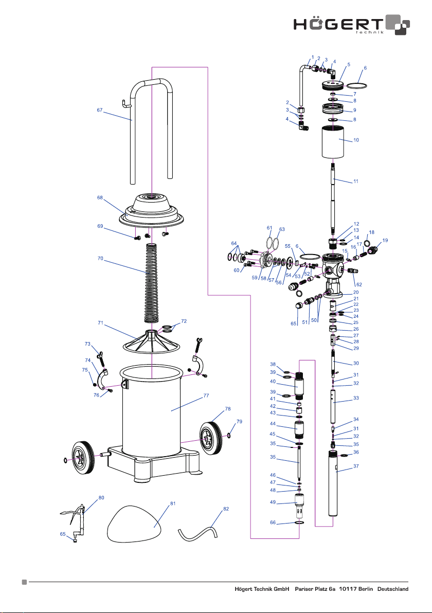
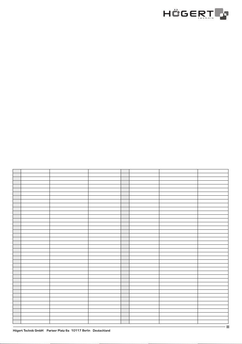
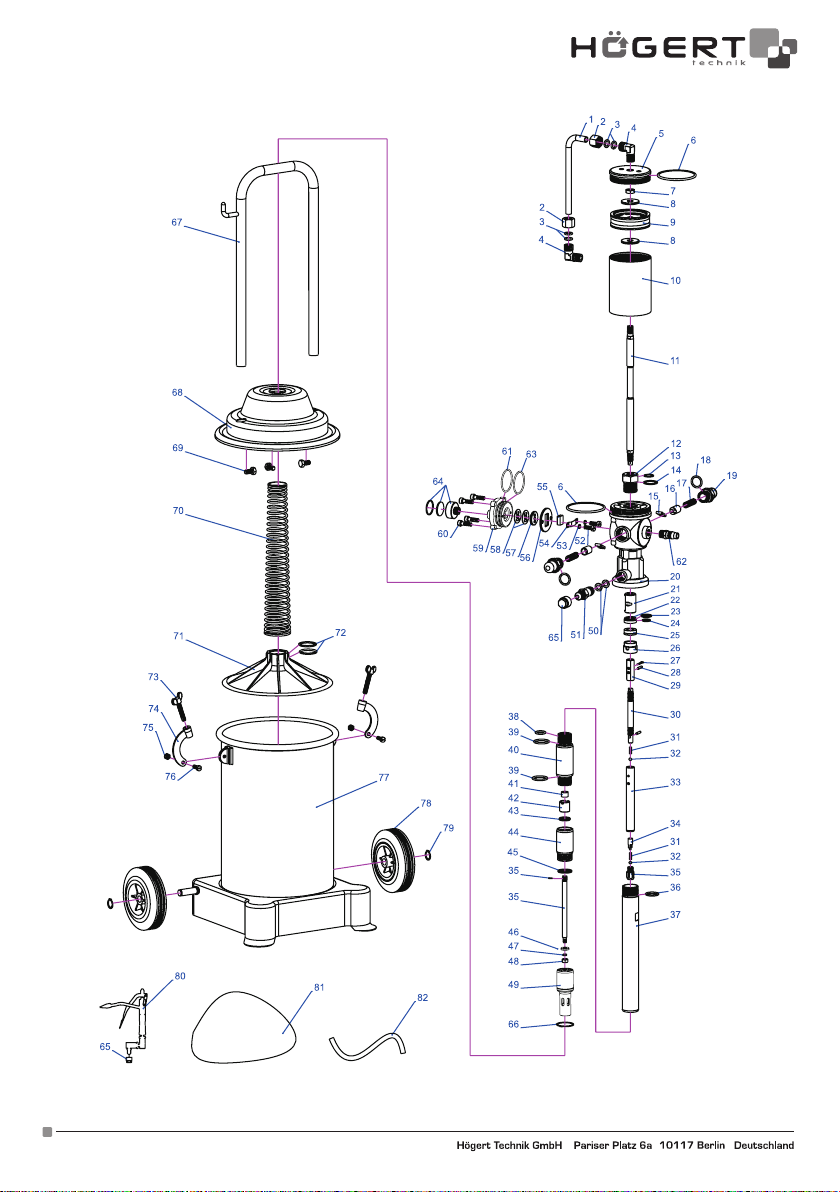
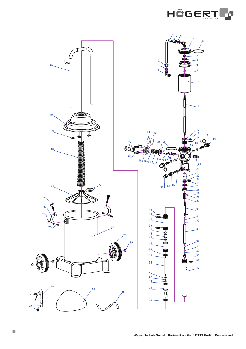
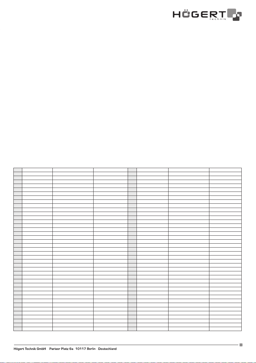
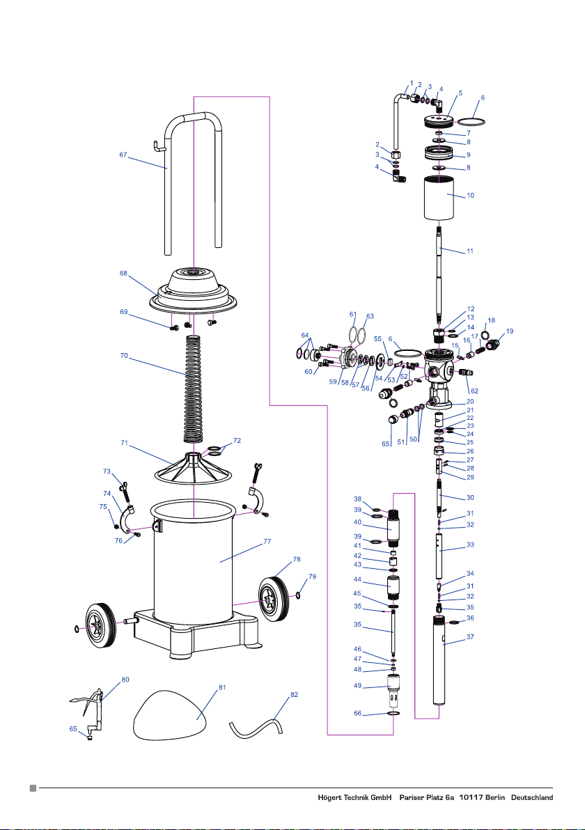
SCHEMAT BUDOWY I LISTA CZĘŚCI
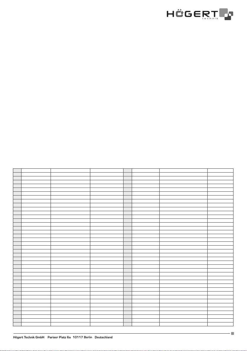
1 RH2121-D-004 przewód powietrza 42 RH1121-12 zawór zwrotny
2 RH1121-02 Nakrętka 43 RH1121-11 uszczelka zaworu
3 GB3452.1-1992 Uszczelka Ø7.5 x 2.65 mm 44 RH1121-13 gniazdo zaworu wlotowego
4 RH1121-03 złącze "L" 45 RH1121-14 pierścień przelewowy
5 RH1121-04 pokrywa cylindra 46 RH2121-D-005 podkładka
6 GB3452.1-1992 Uszczelka Ø 70 x 3.1 mm 47 GB/T 859-1987 uszczelka sprężynowa Ø 6 mm
7 GB/T 6175-2000 Nakrętka 48 GB/T 6175-2000 nakrętka
8 RH1121-07 uszczelka tłoka 49 RH2121-D-003 rura wlotowa smaru
9 RH1121-06 Tłok 50 RH1121-53 podkładka miedziana
10 RH1121-05 cylinder 51 RH1121-15 złącze wylotu smaru
11 RH1121-08/26 trzpień tłoka 52 GB/T 65-2000 śruba
12 RH1121-09 śruba uszczelniająca 53 GB/T 859-1987 uszczelka sprężynowa Ø 4 mm
13 GB3452.1-1992 uszczelka Ø 16 x 2.4 mm 54 RH1121-22 sprężyna tłumiąca
14 GB3452.1-1992 uszczelka Ø 20 x 1.8 mm 55 RH1121-21 bloczek
15 RH1121-11 zawór zwrotny 56 RH1121-20 płytka
16 RH1121-12 tuleja zaworu 57 RH1121-19 płytka
17 RH1121-13 sprężyna 58 RH1121-52 uszczelka
18 GB3452.1-1992 uszczelka Ø 17 x 2.65 mm 59 RH2121-D-002 pokrywa
19 RH1121-14 złączka 60 GB/T70.1-2000 śruby mocujące
20 RH2121-D-001 głowica 61 GB3452.1-1992 uszczelka Ø 46 x 2.50 mm
21 RH1121-23 tuleja 62 RH1121-25 złącze wlotu powietrza
22 RH1121-17 uszczelka 63 GB3452.1-1992 uszczelka Ø 45.3 x 2.65 mm
23 GB3452.1-1992 uszczelka Ø 16 x 1.80 mm 64 RH2121-D-006 Tłumik
24 GB3452.1-1992 uszczelka Ø 11.2 x 1.80 mm 65 RH1121-16 złączka
25 RH1121-18 uszczelka "U" UN 12 x 22 x 8 mm 66 GB 894-86 pierścień zabezpieczający Ø 30 mm
26 RH1121-27 pokrywa uszczelniająca 67 RH1121-18 uchwyt
27 GB/T 91-2000 czop Ø 3 x 20 mm 68 RH1121-19 pokrywa
28 GB/T 879-2000 czop Ø 3 x 15 mm 69 GB/T 5783-2000 śruby mocujące M8 x 15 mm
29 RH1121-02 nakrętka regulacyjna 70 RH1121-51 sprężyna
30 RH1121-03 trzpień 71 RH1121-A-55 dysk dociskowy
31 RH1121-04 sprężyna wlotu smaru 72 GB3452.1-1992 uszczelka Ø 35 x 2.50 mm
32 GB 308-89 stalowa kulka Ø 6 mm 73 RH1121-22 śruby motylkowe
33 RH1121-05 osłona trzpienia 74 RH1121-30 zaciski
34 RH1121-06 tuleja sprężyny 75 GB/T 6184-2000 nakrętki nylonowe
35 RH2121-07/08 dysza 76 GB/T 5783-2000 śruby mocujące M6 x 16 mm
36 GB3452.1-1992 uszczelka Ø 24 x 2.40 mm 77 RH1121-23 pojemnik smaru
37 RH1121-30 rura łącząca 78 RH1121-26 kółka
38 GB3452.1-1992 uszczelka Ø 14 x 2.65 mm 79 GB 894-86 pierścień zabezpieczający Ø 16 mm
39 GB3452.1-1992 uszczelka Ø 20 x 2.65 mm 80 HYQ-200 pistolet
40 RH1121-10 korpus pompy 81 RH1121-27 pokrywa uszczelniająca
41 RH1121-25 uszczelka "U" UN 8 x 14 x 6 mm 82 RH1121-55 przewód
Adres producenta/ Adresse des Herstellers/ Manufacturer’s Address/ Адрес производителя
GTV Poland Sp. z o.o. Sp. k., ul. Przejazdowa 21, 05-800 Pruszków. www.hoegert.com
3
Page 4
4
Adres producenta/ Adresse des Herstellers/ Manufacturer’s Address/ Адрес производителя
GTV Poland Sp. z o.o. Sp. k., ul. Przejazdowa 21, 05-800 Pruszków. www.hoegert.com
Page 5
DE
BENUTZERHANDBUCH
PNEUMATISCHE FETTPRESSE 12 L
Vielen Dank, dass Sie sich für unser Produkt entschieden haben.
Hergestellt nach hohen Standard, wird dieses Produkt, wenn den Anweisungen entsprechend verwendet, und ordnungsgemäß
gewartet, Ihnen störungsfreien Betrieb garantieren.
WARNING
Die pneumatische Fettpresse HT4R795 verwendet Druckluft als Antrieb. Er zeichnet sich durch Zuverlässigkeit, geringen Luftverbrauch, hohen Betriebsdruck, bequeme Bedienung, hohe Leistung, geringen Arbeitsaufwand und die Möglichkeit, hochviskoses Fett
einzuspritzen, aus. Anwendung in Automobil, Landwirtschaft, Industrie.
HAUPTPARAMETER
Druckverhältnis: 50 : 1
Druckluft: 6-8 Bar / 87-116 PSI
Durchmesser des Zylinders: 70 mm
Hub des Zylinders: 35 mm
Leistung: 0,85 l / min
Übertragungsdruck: 300-400 Bar / 4350-5800 PSI
Fassungsvermögen des Schmierstofftanks: 12 kg
Gewicht des Geräts: 16,5 kg
Äußere Abmessungen: 840 x 360 x 320 mm
FUNKTIONSWEISE UND AUFBAU DES GERÄTS
Die pneumatische Fettpresse besteht aus Fetteinspritzpumpe, Fettspritzpistole, Hochdruckschlauch, Schnellkupplung, Fettbehälter.
Die Fetteinspritzpumpe ist mit der oberen Luftpumpe und der unteren Kolbenpumpe verbunden. Die Luftpumpe ist die Antriebspumpe; mit Hilfe von Druckluft wird die Hubkolbenpumpe in eine Vor- und Rückwärts-Bewegung versetzt, um Schmiermitteldruck zu
erzeugen. Da die zulässige Fläche des Zylinderkolbens größer ist als die Fläche des Kolbenzylinders der Kolbenpumpe, kann der
Druck kann deutlich erhöht werden, das richtige Flächenverhältnis beträgt 50 : 1. Bei 6 Bar Druckluft kann der Ausgangsschmierstoffdruck 300 Bar erreichen (ohne Berücksichtigung von Verlusten).
Adres producenta/ Adresse des Herstellers/ Manufacturer’s Address/ Адрес производителя
GTV Poland Sp. z o.o. Sp. k., ul. Przejazdowa 21, 05-800 Pruszków. www.hoegert.com
WICHTIG: BITTE LESEN SIE DIESE ANLEITUNG SORGFÄLTIG DURCH. BEACHTEN SIE DIE SICHEREN BETRIEBSAN-
FORDERUNGEN, WARNHINWEISE UND VORSICHTSMASSNAHMEN.
PFEGEN SIE DAS PRODUUKT UND BENUTZEN SIE ES NUR GEMÄß DEM FÜR IHN BESTIMMTEN ZWECKS. ANDERNFALLS KANN ES ZU SCHÄDEN UND / ODER VERLETZUNGEN KOMMEN, WELCHE ZUM UNWIEDERRUFLICHEN ERLÖSCH DER GARANTIE FÜHREN. BEWAHREN SIE DIESE ANWEISUNGEN FÜR DEN ZUKÜNFTIGEN GEBRAUCH AUF.
5
Page 6
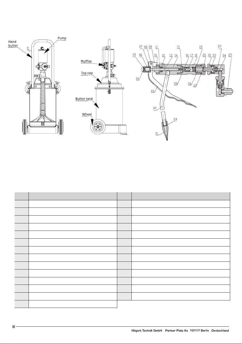
NR Name Nr. Name
1 Spitze 15 Ventilgriff
2 Stutzen 16 Stahlkugel 6 mm
3 Halterung 17 Schmiermittelschlauch
4 Mutter 18 Feder
5 Justierschraube 19 Schmiermittelzuführung
6 Befestigungsschraube 20 Achsenkern
7 Befestigungsschraube 21 Dichtung
8 Niete 22 Stahlkugel 2 mm
9 Schwenkarm 23 Hauptkörper
10 Kompressionsschraube 24/28 Kupferunterlegscheibe
11 Dichtung 25 Fetteinlassanschluss
12 Schmiermitteldichtung 26 Dichtung
13 Oberer Balken 27 Dichtungsring
14 Körper
6
Adres producenta/ Adresse des Herstellers/ Manufacturer’s Address/ Адрес производителя
GTV Poland Sp. z o.o. Sp. k., ul. Przejazdowa 21, 05-800 Pruszków. www.hoegert.com
Page 7
VORBEREITUNG VOR DER VERWENDUNG DES GERÄTS
Schalten Sie den Luftkompressor ein, bereiten Sie Druckluft von 6 bis 8 Bar vor.
Lösen Sie die Gehäuseschrauben des Tankdeckels, kippen Sie die Gehäusehalterungen zusammen mit dem Tankdeckel, der Fetteinspritzpumpe und der Fettpumpvorrichtung in einem Winkel von 20 bis 30 Grad, um Luft unter der Gummidruckplatte einströmen zu
lassen, es ist bequem, sie herauszuziehen, ohne irgendwelche Teile entfernen zu müssen
Die maximale Kapazität des Fettbehälters beträgt 12 kg, die vollständige Installation hängt von den jeweiligen Bedürfnissen ab. Um
Blasenbildung zu vermeiden, sollte das Fett angedrückt werden und die Oberfläche geebnet werden.
Die Halterungen werden zusammen mit dem Deckel, der Fetteinspritzpumpe und den Fettpumpwerkzeugen senkrecht in den Fettbehälter gestellt, die Gummileiste wird fest gegen die Schmierfläche gedrückt. Setzen Sie das Fetteinlassrohr ein, schrauben Sie die
neben dem Behälterdeckel befindliche Halteschraube ein.
Fettinjektionspumpe und Fettinjektionspistole sind über einen Hochdruckschlauch verbunden.
Schließen Sie den Kompressor mit einer Schnellkupplung an den Luftansauganschluss an, lassen Sie Druckluft durchströmen und
schalten Sie die Druckregelpumpe ein, damit sich die Luftpumpe in einer Vor- und Rückwärts-Bewegung bewegen und Luft durch
die Muffe fördern kann. Zu Beginn des Einspritzpumpenbetriebs füllt das Schmiermittel allmählich das Kolbenpumpenrohr, und auch
der Schmiermitteldruck steigt nach dem anfänglichen Betrieb allmählich an. Die Geschwindigkeit der Vor- und Rückwärts-Bewegung
der Einspritzpumpe nimmt bis zum endgültigen Stillstand ab, dann erreicht der Innendruck der Pumpe das Gleichgewicht und der
Druck erreicht ebenfalls den Maximalwert. Wenn der Abzug gedrückt wird, wird Fett aus der Pistole ausgestoßen. Die Fetteinspritzpumpe setzt ihre Vor- und Rückwärts-Bewegung fort, um das Fett nachzufüllen. Wenn das Fett das Kolbenpumpenrohr wieder füllt,
erreicht auch der Fettdruck den Maximalwert und die Fetteinspritzpumpe stoppt die Vor- und Rückwärts-Bewegung. Auf diese Weise
arbeitet die Fetteinspritzpumpe intermittierend. Im Moment des Anhaltens der Einspritzdüse, der Vor- und Rückwärtsbewegung,
des höchsten Drucks des Schmierfetts, ist es notwendig, alle Verbindungsteile zu überprüfen, um sicherzustellen, dass keine Lecks
vorhanden sind.
WARTUNG DES GERÄTES
1. Die Druckluft sollte gefiltert werden, damit keine Verunreinigungen in die Luftpumpe gelangen können.
2. Die Druckluft sollte einen Druck von 8 bar nicht überschreiten.
3. Trennen Sie im Ruhezustand die Luftleitung und ziehen Sie den Pistolenabzug, um das Fett zu entfernen und den Innendruck im
Gerät zu verringern.
5. Die Luftpumpe sollte regelmäßig geschmiert werden.
7. Lassen Sie die Maschine nicht laufen, wenn sich zu wenig Fett im Behälter befindet, um zu verhindern, dass sich die Kolbenpumpe
erhitzt und Teile beschädigt werden.
8. Reinigungs- und Wartungsarbeiten sollten regelmäßig durchgeführt werden, einschließlich der Reinigung des gesamten
Schmiersystems und der Pistole.
KONSTRUKTIONSPLAN UND TEILELISTE.
1 RH2121-D-004 Luftleitung 42 RH1121-12 Rückschlagventil
2 RH1121-02 Mutter 43 RH1121-11 Ventildichtung
3 GB3452.1-1992 Dichtung Ø7.5 x 2.65 mm 44 RH1121-13 Einlassventilbuchse
4 RH1121-03 Anschluss "L" 45 RH1121-14 Überlaufring
5 RH1121-04 Zylinderabdeckung 46 RH2121-D-005 Unterlegscheibe
6 GB3452.1-1992 Dichtung Ø 70 x 3.1 mm 47 GB/T 859-1987 Federdichtung Ø 6 mm
7 GB/T 6175-2000 Mutter 48 GB/T 6175-2000 Mutter
8 RH1121-07 Kolbendichtung 49 RH2121-D-003 Fetteinlassrohr
9 RH1121-06 Kolben 50 RH1121-53 Kupferunterlegscheibe
10 RH1121-05 Zylinder 51 RH1121-15 Fettauslassanschluss
11 RH1121-08/26 Kolbenbolzen 52 GB/T 65-2000 Schraube
12 RH1121-09 Dichtungsschraube 53 GB/T 859-1987 Federdichtung Ø 4 mm
13 GB3452.1-1992 Dichtung Ø 16 x 2.4 mm 54 RH1121-22 Dämpferfeder
14 GB3452.1-1992 Dichtung Ø 20 x 1.8 mm 55 RH1121-21 Block
15 RH1121-11 Rückschlagventil 56 RH1121-20 Platte
16 RH1121-12 Ventilhülse 57 RH1121-19 Platte
17 RH1121-13 Feder 58 RH1121-52 Dichtung
18 GB3452.1-1992 Dichtung Ø 17 x 2.65 mm 59 RH2121-D-002 Abdeckung
19 RH1121-14 Verbinder 60 GB/T70.1-2000 Befestigungsschrauben
20 RH2121-D-001 Kopf 61 GB3452.1-1992 Dichtung Ø 46 x 2.50 mm
21 RH1121-23 Hülse 62 RH1121-25 Luftansaugstutzen
22 RH1121-17 Dichtung 63 GB3452.1-1992 Dichtung Ø 45.3 x 2.65 mm
23 GB3452.1-1992 Dichtung Ø 16 x 1.80 mm 64 RH2121-D-006 Schalldämpfer
24 GB3452.1-1992 Dichtung Ø 11.2 x 1.80 mm 65 RH1121-16 Verbinder
25 RH1121-18 U-Dichtung UN 12 x 22 x 8 mm 66 GB 894-86 Sicherungsring Ø 30 mm
26 RH1121-27 Dichtungsdeckel 67 RH1121-18 Griff
27 GB/T 91-2000 Zapfen Ø 3 x 20 mm 68 RH1121-19 Abdeckung
28 GB/T 879-2000 Zapfen Ø 3 x 15 mm 69 GB/T 5783-2000 Befestigungsschrauben M8 x 15 mm
29 RH1121-02 Einstellmutter 70 RH1121-51 Feder
30 RH1121-03 Stift 71 RH1121-A-55 Druckscheibe
31 RH1121-04 Fetteinlauffeder 72 GB3452.1-1992 Dichtung Ø 35 x 2.50 mm
32 GB 308-89 Stahlkugel Ø 6 mm 73 RH1121-22 Rändelschrauben
33 RH1121-05 Stiftabdeckung 74 RH1121-30 Klemmen
34 RH1121-06 Federhülse 75 GB/T 6184-2000 Nylonmuttern
35 RH2121-07/08 Düse 76 GB/T 5783-2000 Befestigungsschrauben M6 x 16 mm
36 GB3452.1-1992 Dichtung Ø 24 x 2.40 mm 77 RH1121-23 Fettbehälter
37 RH1121-30 Verbindungsrohr 78 RH1121-26 Räder
38 GB3452.1-1992 Dichtung Ø 14 x 2.65 mm 79 GB 894-86 Sicherungsring Ø 16 mm
39 GB3452.1-1992 Dichtung Ø 20 x 2.65 mm 80 HYQ-200 Pistole
40 RH1121-10 Pumpenkörper 81 RH1121-27 Dichtungsdeckel
41 RH1121-25 U-Dichtung UN 8 x 14 x 6 mm 82 RH1121-55 Kabel
Adres producenta/ Adresse des Herstellers/ Manufacturer’s Address/ Адрес производителя
GTV Poland Sp. z o.o. Sp. k., ul. Przejazdowa 21, 05-800 Pruszków. www.hoegert.com
7
Page 8
8
Adres producenta/ Adresse des Herstellers/ Manufacturer’s Address/ Адрес производителя
GTV Poland Sp. z o.o. Sp. k., ul. Przejazdowa 21, 05-800 Pruszków. www.hoegert.com
Page 9
EN
USER'S MANUAL
HIGH PRESSURE GREASE PUMP 12
Thank you for purchasing our Product. Manufactured to a high standard this product will, if used according to these
instructions andproperly maintained, give you years of trouble free performance.
WARNING
HT4R795 high-pressure grease injector uses compressed as drive, the pump creates the high-pressure by pressing the grease, and the
oil injected by the high pressure. The grease injector is becoming the essential equipment in oil injected industralization. Its features are
good reliability, low air consumption, high working pressure, convienient usage, high effi ciency of production, loe labor intension, capability
of injecting grease of high viscidity. Applying in automobile, tractors and ather dynamic machines grease injection aspects.
MAIN TECHNOLOGY PARAMETERS
Pressure ratio: 50 : 1
Compressed air: 6-8 Bar / 87-116 PSI
Air cylinder diameter: 70 mm
Journey: 35 mm
Grease transmission velocity: 0,85 l / min
Transmission pressure: 300-400 Bar / 4350-5800 PSI
Capacity of grease container: 12 kg
Weight of equipment: 16,5 kg
Outline dimension: 840 x 360 x 320 mm
OPERATION AND STRUCTURE OF EQUIPMENT
High pressure grease injector is composed by grease inject pump, grease inject, high pressure tube, quick changing connector, grease
storage vehicle. The grease inject pump is combined with upper air pump and lower plunger piston pump. Air pump is the driving
pump of plunger piston pump. Compressed air is used to drive the plunger piston pump in reciprocating motion for grease inlet grease
outlet and creating the grease pressure. Becauce of the valid area of the piston of cylinder is bigger than that of cylinder of plunger
piston pump, so pressure can be greatly enhanced. The valid area ratio is 50 : 1 (named as pressure ratio). When 6 Bar compressed air
inputted, the output grease pressure can reach 300 Bar (omit wastage).
Adres producenta/ Adresse des Herstellers/ Manufacturer’s Address/ Адрес производителя
GTV Poland Sp. z o.o. Sp. k., ul. Przejazdowa 21, 05-800 Pruszków. www.hoegert.com
IMPORTANT: PLEASE READ THESE INSTRUCTIONS CAREFULLY. NOTE THE SAFE OPERATIONAL REQUIREMENTS, WARNINGS & CAUTIONS. USE THE PRODUCT CORRECTLY AND WITH CARE FOR THE PURPOSE FOR
WHICH IT IS INTENDED. FAILURE TO DO SO MAY CAUSE DAMAGE AND/OR PERSONAL INJURY AND WILL
INVALIDATE THE WARRANTY. KEEP THESE INSTRUCTIONS SAFE FOR FUTURE USE.
9
Page 10
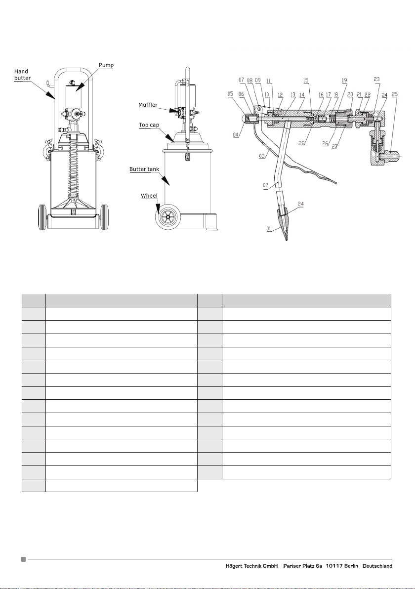
No. Name No. Name
1 Gun mouth 15 Valve holder
2 Drill tubing 16 6 mm Steel ball
3 Handle 17 Steel ball place
4 Round head nut 18 Spring
5 Adjust the screw rod 19 Takes over control
6 Thin nut 20 Core axis
7 Thick nut 21 Seals the nut I
8 Rivet 22 2 mm Steel ball
9 Including contact tag 23 Attachment body
10 Compression screw 24/28 Red copper pad
11 Seal filling pice 25 Grease-inlet connector
12 Grease seal 26 Seals the nut II
13 Roof bar 27 O type seal ring
14 Korpus
10
Adres producenta/ Adresse des Herstellers/ Manufacturer’s Address/ Адрес производителя
GTV Poland Sp. z o.o. Sp. k., ul. Przejazdowa 21, 05-800 Pruszków. www.hoegert.com
Page 11
PREPARATION BEFORE USING THE DEVICE
Switch on the air compressor, have 6 to 8 Bar compressed air in preparation.
Screw off the dishing houslong screws beside the two sides of tank cover. Tilt the handles of body with the tank cover, grease injection
pump and grease pressing device to an angle of 20 to 30 degrees. To let air enter through the bottom of oil pressure rubber board. It is
convenient to pul lit out without the necessity of uninstalling any parts.
The maximum capacity of lubricant grease to be installed in grease storage tank is 12 kg. Full instalation is depending on requirement.
To prevent the buble from creating, the grease should be pressed and Surface should be planed.
The handles of cars with the cover, grease injection pump and grease pressing devices are placed vertically into the grease storage
tank. Press the rubber board tightly on the grease surface. Insert the grease inlet pipe into the bottom of the cabinet, screw on the
dishing tightening screw beside the tank cover. Install the quick replacing connector in the air source pipe.
The grease injection pump and grease injection gun are connected by the high pressure pipe. The cleaning job should be finished
during the connection. At the beginning of the grease injection pump the grease gradually filled in the pipe of plung piston pump. The
grease pressure also increasing gradually after working project. The velocity of reciprocating motion of grease injection pump decreased. Till the final stop, then the inner pressure of pump reaches the equilibrium. The pressure also reaches the maximum value this
time. If trigger of grease injection pump is pulled, high pressure will inject from the gun. When the grease filled in the pipe of plunge
piston pump again. The grease pressure also reaches the maximum value and the grease injection pump stops the reciprocating
motion. The grease injection pump is thus working discontinuously.
At the time of grease injection pump stop the reciprocating motion highest grease pressure it is necessary to check all connecting
parts to ensure noleak exist.
MAINTENACE EQUIPMENT
1. The compressed air should be filtrated to keep the dirt in air from entering the air pump to abrade the air supply sliding block,
cylinder etc.
2. The compressed air should not sulpass 8 Bar, so as to prevent overloading and effect the longevity of high pressure pipe.
3. While using the high pressure pipe forcing bending and heavy loading is forbidden to prevent damage.
4. During the rest time, the quick replacing connector should be uninstalled and pull trigger of grease injection gun to emit the grease,
so as to decrease the inner grease pressure of the equipment to extend the longevity of high pressure pipe.
5. Lubricant grease should be injected into the air pump regularly.
6. In the disassembling proces, avoid the touching of each part to keep the accuracy of the disassembled parts.
7. Do not run the machine without loads while the grease is insifficent in storage tank, so as to prevent heating the plunge piston pump
to damage parts.
8. Cleaning and maintenance job should be done regularly.
GREASE INJECTOR PART LIST
1 RH2121-D-004 Air tube 42 RH1121-12 Check valve
2 RH1121-02 Air tube Nut 43 RH1121-11 Check valve gasket
3 GB3452.1-1992 O type seal ring Ø7.5 x 2.65 mm 44 RH1121-13 Grease inlet valve seating
4 RH1121-03 Bend connector 45 RH1121-14 Overflow ring
5 RH1121-04 Cylinder cover 46 RH2121-D-005 Loading board
6 GB3452.1-1992 O type seal ring Ø 70 x 3.1 mm 47 GB/T 859-1987 Spring gasket Ø 6 mm
7 GB/T 6175-2000 Turret Nut 48 GB/T 6175-2000 Turret Nut
8 RH1121-07 Piston Gasket 49 RH2121-D-003 Grease inlet pipe
9 RH1121-06 Piston 50 RH1121-53 Purplr copper gasket
10 RH1121-05 Cylinder 51 RH1121-15 Grease outlet connector
11 RH1121-08/26 Piston pole module 52 GB/T 65-2000 Deck bolt
12 RH1121-09 Seal screw 53 GB/T 859-1987 Spring gasket Ø 4 mm
13 GB3452.1-1992 O type seal ring Ø 16 x 2.4 mm 54 RH1121-22 Damping spring
14 GB3452.1-1992 O type seal ring Ø 20 x 1.8 mm 55 RH1121-21 Gas-supplier slide block
15 RH1121-11 R everse valve 56 RH1121-20 Clapboard
16 RH1121-12 Valve sleeves 57 RH1121-19 Gas-supplierseatlng
17 RH1121-13 Reverse spring 58 RH1121-52 Paper gasket
18 GB3452.1-1992 O type seal ring Ø 17 x 2.65 mm 59 RH2121-D-002 Gas supplier rover
19 RH1121-14 Slide seating 60 GB/T70.1-2000 Inside hexangular cylinder head bolt
20 RH2121-D-001 Gas supplier 61 GB3452.1-1992 O type seal ring Ø 46 x 2.50 mm
21 RH1121-23 Pulling sheath 62 RH1121-25 Ąir·inlet connector
22 RH1121-17 Sealing gasket 63 GB3452.1-1992 O type seal ring Ø 45.3 x 2.65 mm
23 GB3452.1-1992 O type seal ring Ø 16 x 1.80 mm 64 RH2121-D-006 Muffler
24 GB3452.1-1992 O type seal ring Ø 11.2 x 1.80 mm 65 RH1121-16 Learning oil caul king
25 RH1121-18 U seal ring UN 12 x 22 x 8 mm 66 GB 894-86 Axis Cir Ciip Ø 30 mm
26 RH1121-27 Sealing cover 67 RH1121-18 Hand butter
27 GB/T 91-2000 Dowel Ø 3 x 20 mm 68 RH1121-19 Top cap
28 GB/T 879-2000 Dowel Ø 3 x 15 mm 69 GB/T 5783-2000 Hexangular head stud bolt M8 x 15 mm
29 RH1121-02 Adjust nut 70 RH1121-51 Presses Oil Spring
30 RH1121-03 Connectlng pole 71 RH1121-A-55 Presses oil disk
31 RH1121-04 Grease inlet spring 72 GB3452.1-1992 O type seal ring Ø 35 x 2.50 mm
32 GB 308-89 Steel bali Ø 6 mm 73 RH1121-22 Butterfly shaped nut
33 RH1121-05 Plunger piston pole 74 RH1121-30 ShacKle
34 RH1121-06 Spring seating 75 GB/T 6184-2000 Nylon Nut
35 RH2121-07/08 Loading pole module 76 GB/T 5783-2000 Hexangular head stud bolt M6 x 16 mm
36 GB3452.1-1992 O type seal ring Ø 24 x 2.40 mm 77 RH1121-23 Butter Tank
37 RH1121-30 Connecting pipe 78 RH1121-26 Wheels
38 GB3452.1-1992 O type seal ring Ø 14 x 2.65 mm 79 GB 894-86 Axis Cir Ciip Ø 16 mm
39 GB3452.1-1992 O type seal ring Ø 20 x 2.65 mm 80 HYQ-200 Gun
40 RH1121-10 Pump body 81 RH1121-27 Spare part list
41 RH1121-25 U seal ring UN 8 x 14 x 6 mm 82 RH1121-55 High pressure pipe
Adres producenta/ Adresse des Herstellers/ Manufacturer’s Address/ Адрес производителя
GTV Poland Sp. z o.o. Sp. k., ul. Przejazdowa 21, 05-800 Pruszków. www.hoegert.com
11
Page 12
12
Adres producenta/ Adresse des Herstellers/ Manufacturer’s Address/ Адрес производителя
GTV Poland Sp. z o.o. Sp. k., ul. Przejazdowa 21, 05-800 Pruszków. www.hoegert.com
Page 13
RU
РУКОВОДСТВО ЭКСПЛУАТАЦИИ
ПНЕВМАТИЧЕСКИЙ СМАЗЧИК 12 Л HT4R795
Спасибо за покупку нашего продукта. Данный продукт изготовлен в соответствии с высокими стандартами и даст
Вам годы бесперебойной работы, если он используется в соответствии с настоящей инструкцией и должным образом
сервисуется.
WARNING
ДЛЯ БУДУЩЕГО ИСПОЛЬЗОВАНИЯ.
Пневматический смазочный пистолет HT4R795 использует сжатый воздух в качестве привода. Она характеризуется
надежностью, низким расходом воздуха, высоким рабочим давлением, удобством использования, высокой эффективностью,
низким уровнем технического обслуживания, способностью впрыскивать смазку высокой вязкости. Применение
в автомобилестроении, сельском хозяйстве, промышленности.
ОСНОВНЫЕ ПАРАМЕТРЫ
Коэффициент давления: 50 : 1
Сжатый воздух: 6-8 бар / 87-116 PSI
Диаметр цилиндра: 70 мм
Ход цилиндра: 35 мм
Производительность: 0,85 л/мин
Давление передачи: 300-400 Бар / 4350-5800 PSI
Вместимость бака для смазки: 12 кг
Вес единицы: 16,5 кг
Наружные размеры: 840 x 360 x 320 мм
ЭКСПЛУАТАЦИЯ И КОНСТРУКЦИЯ ОБОРУДОВАНИЯ
Пневматический смазочный пистолет состоит из смазочного насоса, смазочного пистолета, трубы высокого давления,
быстроразъемной муфты, контейнера для смазки.
Насос для впрыска смазки соединен с верхним воздушным насосом и нижним поршневым насосом. Воздушный насос - это
приводной насос; сжатый воздух используется для привода поршневого насоса в возвратно-поступательном движении для
создания давления смазки. В связи с тем, что допустимая площадь поверхности поршня цилиндра больше площади поверхности
поршневого цилиндра поршневого насоса, давление может быть значительно увеличено, правильное соотношение площади
поверхности 50 : 1. При использовании сжатого воздуха 6 бар давление смазки на выходе может достигать 300 бар (без учета
потерь).
Adres producenta/ Adresse des Herstellers/ Manufacturer’s Address/ Адрес производителя
GTV Poland Sp. z o.o. Sp. k., ul. Przejazdowa 21, 05-800 Pruszków. www.hoegert.com
ВАЖНО: ПОЖАЛУЙСТА, ВНИМАТЕЛЬНО ПРОЧИТАЙТЕ ДАННУЮ ИНСТРУКЦИЮ. ОБРАТИТЕ
ВНИМАНИЕ НА ЭКСПЛУАТАЦИОННЫЕ ТРЕБОВАНИЯ БЕЗОПАСНОСТИ, ПРЕДУПРЕЖДЕНИЯ И МЕРЫ
ПРЕДОСТОРОЖНОСТИ. ИСПОЛЬЗУЙТЕ ДАННЫЙ ПРОДУКТ ПРАВИЛЬНО ДЛЯ ЦЕЛЕЙ, ДЛЯ КОТОРЫХ ОН
ПРЕДНАЗНАЧЕН. НЕСПОСОБНОСТЬ СДЕЛАТЬ ЭТО МОЖЕТ ВЫЗВАТЬ ПОВРЕЖДЕНИЕ ИЛИ ТРАВМУ И
ПРИВЕСТИ К АННУЛИРОВАНИЮ ГАРАНТИИ. ПОЖАЛУЙСТА, СОХРАНИТЕ ИНСТРУКЦИЮ БЕЗОПАСНОСТИ
13
Page 14
NR Name Nr. Name
1 Наконечник 15 Рукоятка клапана
2 Насадка 16 Стальной шарик 6 мм
3 Рукоятка 17 Смазочная трубка
4 Крышка 18 Пружина
5 Регулировочный винт 19 Подача смазки
6 Зажимной винт 20 Ядро оси
7 Зажимной винт 21 Прокладка
8 Заклепка 22 Стальной шарик 2 мм
9 Поворотный кронштейн 23 Основной корпус
10 Компрессионный винт 24/28 Медная шайба
11 Прокладка 25 Впускной патрубок смазки
12 Смазочное уплотнение 26 Прокладка
13 Верхняя балка 27 Уплотнительное кольцо
14 Корпус
14
Adres producenta/ Adresse des Herstellers/ Manufacturer’s Address/ Адрес производителя
GTV Poland Sp. z o.o. Sp. k., ul. Przejazdowa 21, 05-800 Pruszków. www.hoegert.com
Page 15
ПОДГОТОВКА ПЕРЕД ИСПОЛЬЗОВАНИЕМ УСТРОЙСТВА
Включите воздушный компрессор, подготовьте сжатый воздух от 6 до 8 бар.
Ослабьте винты корпуса крышки бака, наклоните кронштейны корпуса вместе с крышкой бака, насосом впрыска смазки и
устройством подачи смазки под углом 20-30 градусов, чтобы позволить воздуху войти из-под резиновой нажимной плиты и
удобно вытащить его без извлечения каких-либо частей. Максимальная вместимость консистентной смазки, устанавливаемой
в резервуар для смазки, составляет 12 кг, полная установка зависит от ваших потребностей. Для предотвращения образования
пузырьков смазку следует прижать, а поверхность должна быть ровной. Держатели вместе с крышкой, насосом для
впрыскивания консистентной смазки, насосными устройствами для впрыскивания консистентной смазки располагаются
вертикально в резервуаре с консистентной смазкой, плотно прижимают резиновую ленту к поверхности консистентной смазки.
Вставить трубу для впуска смазки, ввинтить крепежный винт, расположенный рядом с крышкой резервуара.
Насос и пистолет для впрыскивания смазки подключаются через шланг высокого давления.
Соедините компрессор с быстроразъемным соединением с патрубком подачи воздуха, пропустите сжатый воздух и включите
насос регулирования давления, чтобы воздушный насос мог перемещаться в возвратно-поступательном движении и подавать
воздух через патрубок. В начале работы инжекторного насоса смазка будет постепенно заполнять трубку поршневого насоса, а
давление смазки будет также постепенно возрастать после начальной работы. Скорость возвратно-поступательного движения
инжекторного насоса уменьшается до конечной остановки, затем внутреннее давление насоса достигает равновесия, а
давление также достигает максимального значения. При нажатии на спусковой крючок из пистолета выбрасывается смазка.
Насос для впрыскивания смазки продолжит возвратно-поступательное движение, чтобы пополнить смазку. Когда смазка
снова заполнит трубку поршневого насоса, давление смазки также достигнет своего максимального значения, и насос для
впрыскивания смазки прекратит свое возвратно-поступательное движение Таким образом, насос для впрыскивания смазки
работает с перерывами. Когда насос для впрыскивания смазки останавливает возвратно-поступательное движение при
наибольшем давлении смазки, необходимо проверить все соединительные детали, чтобы убедиться в отсутствии утечек.
ОБСЛУЖИВАНИЕ ОБОРУДОВАНИЯ
1. Сжатый воздух должен быть отфильтрован, чтобы предотвратить попадание загрязнений в воздушный насос.
2. давление сжатого воздуха не должно превышать 8 бар.
3. отсоедините воздушную линию в состоянии покоя и нажмите на спусковой крючок пистолета, чтобы удалить смазку для снижения
внутреннего давления в устройстве.
4. Воздушный насос следует регулярно смазывать.
5. Hе запускайте машину, если в резервуаре слишком мало смазки, чтобы поршневой насос не нагревался и не повреждал детали.
6. Работы по очистке и техническому обслуживанию должны проводиться регулярно, очистка всей системы смазки, пистолета.
1 RH2121-D-004 вентиляционная труба 42 RH1121-12 обратный клапан
2 RH1121-02 Гайка 43 RH1121-11 уплотнение клапана
3 GB3452.1-1992 Прокладка Ø7.5 x 2.65 мм 44 RH1121-13 седло впускного клапана
4 RH1121-03 разъём "L" 45 RH1121-14 обходное кольцо
5 RH1121-04 крышка цилиндра 46 RH2121-D-005 подкладка
6 GB3452.1-1992 Прокладка Ø 70 x 3.1 мм 47 GB/T 859-1987 пружинная прокладка Ø 6 мм
7 GB/T 6175-2000 Гайка 48 GB/T 6175-2000 гайка
8 RH1121-07 uszczelka tłoka 49 RH2121-D-003 подводящая смазка трубы
9 RH1121-06 Поршень 50 RH1121-53 медная шайба
10 RH1121-05 цилиндр 51 RH1121-15 выходной смазочный фитинг
11 RH1121-08/26 поршневой палец 52 GB/T 65-2000 винтовой
12 RH1121-09 уплотнительный винт 53 GB/T 859-1987 пружинное уплотнение Ø 4 мм
13 GB3452.1-1992 Прокладка Ø 16 x 2.4 мм 54 RH1121-22 амортизационная пружина
14 GB3452.1-1992 Прокладка Ø 20 x 1.8 мм 55 RH1121-21 шкив
15 RH1121-11 обратный клапан 56 RH1121-20 пластинка
16 RH1121-12 Втулка клапана 57 RH1121-19 пластинка
17 RH1121-13 пружина 58 RH1121-52 Прокладка
18 GB3452.1-1992 Прокладка Ø 17 x 2.65 мм 59 RH2121-D-002 крышка
19 RH1121-14 коннектор 60 GB/T70.1-2000 крепёжные шурупы
20 RH2121-D-001 основа 61 GB3452.1-1992 Прокладка Ø 46 x 2.50 мм
21 RH1121-23 втулка 62 RH1121-25 Коннектор воздухозаборника
22 RH1121-17 Прокладка 63 GB3452.1-1992 Прокладка Ø 45.3 x 2.65 мм
23 GB3452.1-1992 Прокладка Ø 16 x 1.80 мм 64 RH2121-D-006 Глушитель
24 GB3452.1-1992 Прокладка Ø 11.2 x 1.80 мм 65 RH1121-16 соединитель
25 RH1121-18 Прокладка "U" UN 12 x 22 x 8 мм 66 GB 894-86 стопорное кольцо Ø 30 мм
26 RH1121-27 уплотнительная крышка 67 RH1121-18 рукоятка
27 GB/T 91-2000 чопик Ø 3 x 20 мм 68 RH1121-19 заслонка
28 GB/T 879-2000 чопик Ø 3 x 15 мм 69 GB/T 5783-2000 крепёжные шурупы M8 x 15 мм
29 RH1121-02 регулировочная гайка 70 RH1121-51 пружина
30 RH1121-03 стержень 71 RH1121-A-55 нажимной диск
31 RH1121-04 пружина впуска смазки 72 GB3452.1-1992 Прокладка Ø 35 x 2.50 мм
32 GB 308-89 стальной шар Ø 6 мм 73 RH1121-22 барашковые винты
33 RH1121-05 крышка хвостовика 74 RH1121-30 хомуты
34 RH1121-06 пружинная втулка 75 GB/T 6184-2000 нейлоновые гайки
35 RH2121-07/08 насадка 76 GB/T 5783-2000 крепёжные шурупы M6 x 16 мм
36 GB3452.1-1992 Прокладка Ø 24 x 2.40 мм 77 RH1121-23 Контейнер для смазки
37 RH1121-30 соединительная труба 78 RH1121-26 колёсики
38 GB3452.1-1992 Прокладка Ø 14 x 2.65 мм 79 GB 894-86 стопорное кольцо Ø 16 мм
39 GB3452.1-1992 Прокладка Ø 20 x 2.65 мм 80 HYQ-200 пистолет
40 RH1121-10 корпус насоса 81 RH1121-27 уплотнительная крышка
41 RH1121-25 прокладка"U" UN 8 x 14 x 6 мм 82 RH1121-55 провод
КОНСТРУКТИВНАЯ СХЕМА И ПЕРЕЧЕНЬ ДЕТАЛЕЙ.
Adres producenta/ Adresse des Herstellers/ Manufacturer’s Address/ Адрес производителя
GTV Poland Sp. z o.o. Sp. k., ul. Przejazdowa 21, 05-800 Pruszków. www.hoegert.com
15
Page 16
16
Adres producenta/ Adresse des Herstellers/ Manufacturer’s Address/ Адрес производителя
GTV Poland Sp. z o.o. Sp. k., ul. Przejazdowa 21, 05-800 Pruszków. www.hoegert.com
 Loading...