

Page 1
PL
INSTRUKCJA OBSŁUGI
ZESTAW DO LUTOWANIA GAZOWEGO
HT2C511, HT2C512, HT2C513, HT2C514
Dziękujemy za zakup naszego produktu. Wyprodukowany zgodnie
z wysokim standardem produkt zapewni lata bezproblemowej pracy pod
warunkiem stosowania zgodnie z instrukcją i odpowiednio utrzymany.
1. Upewnij się, że zawór palnika jest szczelnie zamknięty. Moment
zamykania zaworu powinien wynosić 0,3 N/m.
2. Podłączyć wąż do palnika za pomocą odpowiednich kluczy.
3. Podłącz wąż do regulatora ciśnienia, a następnie do kranu. UWAGA:
Sprawdzić, czy pomiędzy regulatorem ciśnienia a kurkiem butli
znajduje się uszczelka. Jeśli występuje, zawór nadmuchowy musi być
umieszczony między wężem a regulatorem ciśnienia.
4. Otworzyć zawór butli.
5. Sprawdź uszczelki między palnikiem a rurą oraz między rurą a cylindrem
za pomocą odpowiedniego detektora (tego samego typu co art. 1726).
6. W przypadku wycieku zamknij butlę i ponownie sprawdź szczelność
i uszczelnienia. Jeśli problem będzie się powtarzał, skontaktuj się ze
sprzedawcą.
7. Otworzyć umiarkowanie zawór kranu (1/2 obrotu) w kierunku
przeciwnym do ruchu wskazówek zegara i umieścić płomień na dyszy lub
nacisnąć przycisk zapłonu (w modelach z zapłonem piezoelektrycznym).
8. Następnie całkowicie otwórz kran, aby uzyskać maksymalną moc
palnika.
9. Po zakończeniu pracy zawsze najpierw zamykaj zawór butli, a następnie
zawór palnika.
10. Podczas wymiany butli zawsze pracuj w dobrze wentylowanym miejscu,
z dala od źródeł ciepła i otwartego ognia. Następnie powtórz czynności
opisane w punkcie 1.
OSTRZEŻENIA
11. Stosować wyłącznie z propanem o ciśnieniu od 0,5 do 3 BAR.
12. Nie używać ze stałymi regulatorami kalibracji do użytku domowego,
ponieważ dostarczane ciśnienie jest niewystarczające.
13. Używaj tylko na zewnątrz w dobrze wentylowanych miejscach.
14. Po zakończeniu pracy dysza będzie bardzo gorąca; przechowywać
w bezpiecznym miejscu z dala od materiałów łatwopalnych.
15. Wszelkie prace przy urządzeniu muszą być wykonywane przez
wyspecjalizowany personel autoryzowany przez Producenta. Używaj
tylko oryginalnych części zamiennych.
16. Zalecamy używanie palnika z zaworem nadmuchowym.
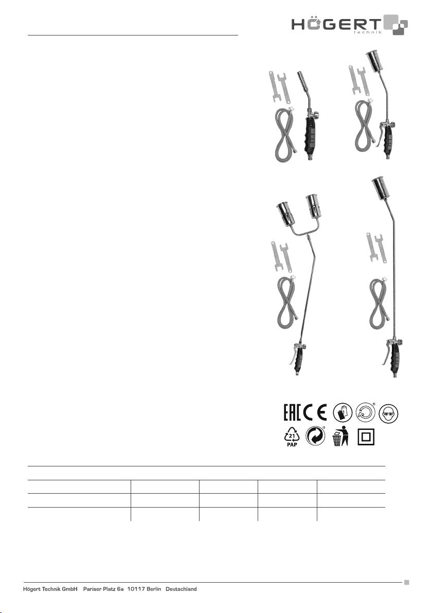
HT2C511
HT2C513
HT2C512
HT2C514
Tabela zużycia
Dysza
Ciśnienie 20 30 45 60
0. 5 BAR 0.12 kg/h 0.39 kg/h 0.85 kg/h 2.20 kg/h
3 BAR 0.31 kg/h 1.00 kg/h 2.25 kg/h 5.70 kg/h
Adres producenta/ Adresse des Herstellers/ Manufacturer’s Address/ Адрес производителя
GTV Poland S.A., ul. Przejazdowa 21, 05-800 Pruszków, www.hoegert.com
1
Page 2
8
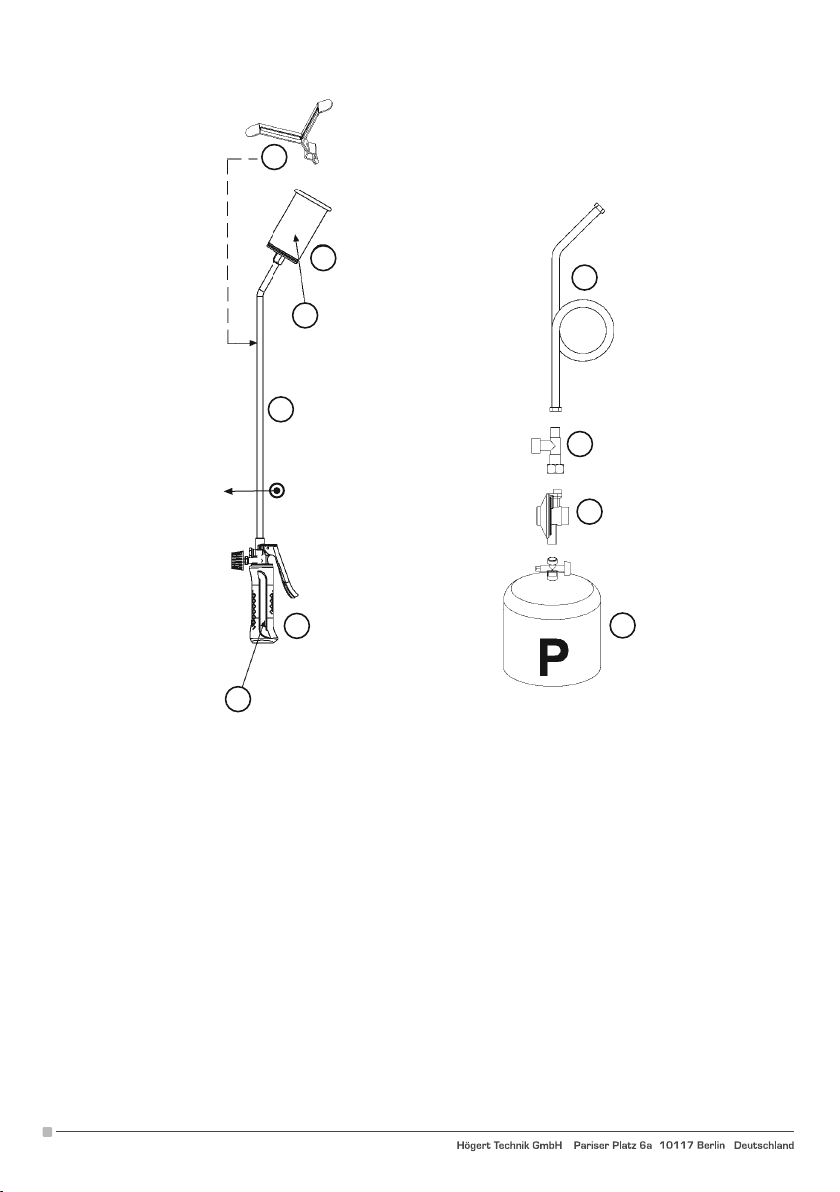
ZAWARTOŚĆ
1. Dysza
2. Rozszerzenie
3. Pochodnia
10
1
4
9
2
5
6
3
7
AKCESORIA OPCJONALNE
4. Wąż wysokociśnieniowy (min. 20 BAR) - średnica wewnętrzna ok. 8 mm. Używaj tylko zatwierdzonych węży
5. Zawór wybuchowy
6. Regulator ciśnienia 0-3 BAR
7. Butla z propanem
8. Jarzmo
ZNAKOWANIA
9. Nazwa producenta
Dopuszczalne gazy (P-GPL/LPG)
Konsumpcja
2
Adres producenta/ Adresse des Herstellers/ Manufacturer’s Address/ Адрес производителя
GTV Poland S.A., ul. Przejazdowa 21, 05-800 Pruszków, www.hoegert.com
Page 3
EN
INSTRUCTIONS FOR USE
GAS WELDING KIT
HT2C511, HT2C512, HT2C513, HT2C514
Thank you for purchasing our product. Manufactured to a high standard,
this product will, if used according to these
instructions, and properly maintained, give you years of trouble free performance.
1. Ensure that the torch tap is tightly closed. The closing torque of the valve
should be 0.3 N/m.
2. Connect the hose to the torch with the use of appropriate spanners.
3. Connect the hose to the pressure regulator and then to the tap. CAUTION:
Check whether there is a gasket between the pressure regulator and the
cylinder tap. If any, the blast valve must be positioned between the hose
and the pressure regulator.
4. Open the cylinder tap.
5. Check the seals between the torch and the tube and between the tube
and the cylinder with a proper detector (the same type as art. 1726).
6. If there is any leakage, close the cylinder and check the tightness and
seals again. If the problem persists, contact your dealer.
7. Open the tap's valve moderately (1/2 turn) anti-clockwise and place a
flame on the nozzle or press the ignition button (for models with piezo
ignition).
8. Then open the tap fully to obtain maximum power from the torch.
9. When you have finished working, always close the cylinder tap first, then
the torch tap.
10. When replacing the cylinder, always work in a well-ventilated area away
from sources of heat and open flames. Then repeat the operations
described in point 1.
WARNINGS
11. Use only with propane gas at a pressure between 0.5 and 3 BAR.
12. Do not use with fixed calibration regulators for domestic use as the
pressure supplied is insufficient.
13. Use only outdoors in well-ventilated places.
14. Once you finish work, the nozzle will be very hot; store it in a safe place
away from flammable materials.
15. Any work on the equipment must be performed by specialised
personnel authorised by the Manufacturer. Use only original spare
parts.
16. We recommend using the torch with the blast valve. .
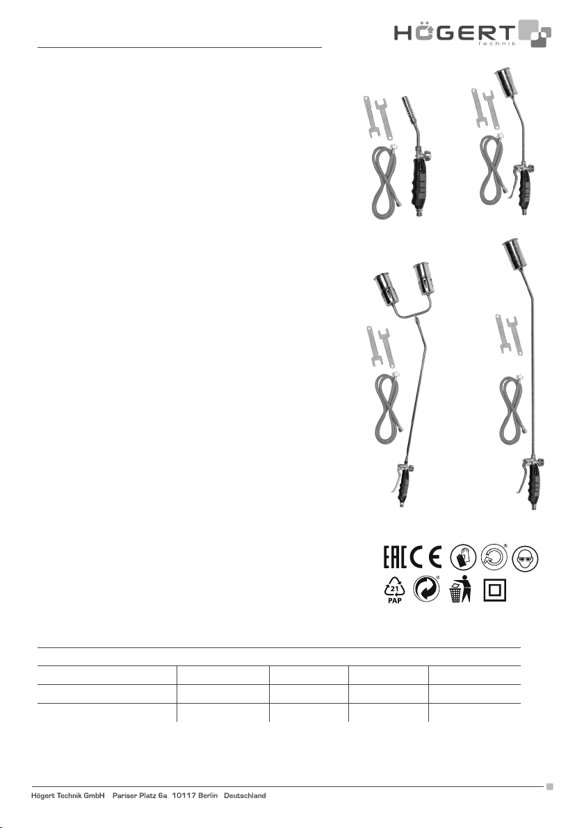
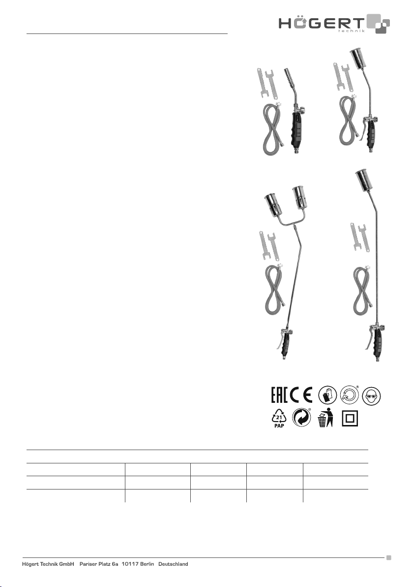
HT2C511
HT2C513
HT2C512
HT2C514
Consumption table
Nozzle
Pressure 20 30 45 60
0. 5 BAR 0.12 kg/h 0.39 kg/h 0.85 kg/h 2.20 kg/h
3 BAR 0.31 kg/h 1.00 kg/h 2.25 kg/h 5.70 kg/h
Adres producenta/ Adresse des Herstellers/ Manufacturer’s Address/ Адрес производителя
GTV Poland S.A., ul. Przejazdowa 21, 05-800 Pruszków, www.hoegert.com
3
Page 4
8
1
4
9
2
5
6
3
10
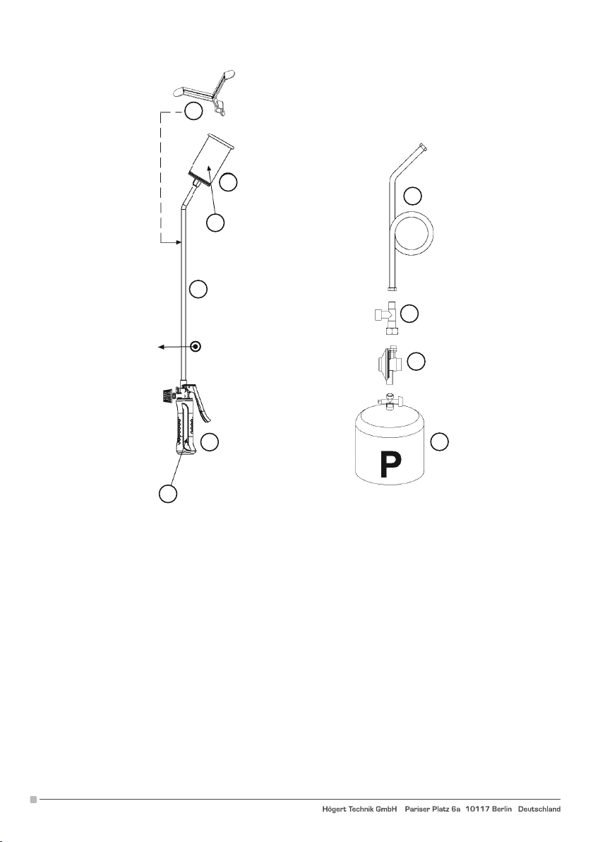
CONTENUTO-CONTENTS-CONTENTU-INHALT-CONTENIDO
1. Nozzle
2. Extension
3. Torch
OPTIONAL ACCESSORIES
4. High pressure hose (min. 20 BAR) - internal diameter of approx. 8 mm. Use only approved hoses
5. Blast valve
6. Pressure regulator 0-3 BAR
7. Propane cylinder
8. Yoke
MARKINGS
9. lndicazione di-Indication of-Indication de: Manufacturer name
Permissible gases (P- GPL/LPG)
Consumption
7
4
Adres producenta/ Adresse des Herstellers/ Manufacturer’s Address/ Адрес производителя
GTV Poland S.A., ul. Przejazdowa 21, 05-800 Pruszków, www.hoegert.com
Page 5
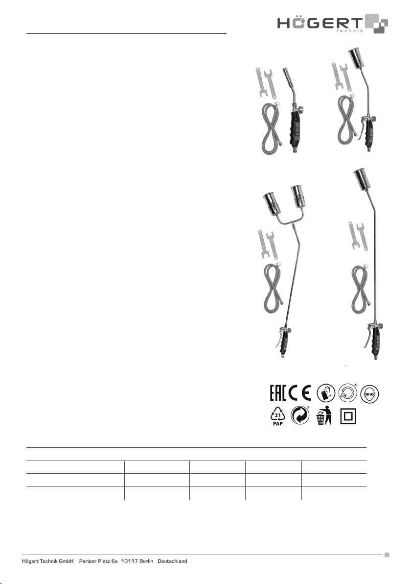
DE
BENUTZERHANDBUCH LÖTKOLBEN
GASSCHMELZSCHWEISS-KIT
HT2C511, HT2C512, HT2C513, HT2C514
Vielen Dank, dass Sie sich für unser Produkt entschieden haben.
Hergestellt nach hohen Standard, wird dieses Produkt, wenn den Anweisungen entsprechend verwendet, und ordnungsgemäß gewartet, Ihnen
störungsfreien Betrieb garantieren.
1. Vergewissern Sie sich, dass der Hahn des Schweißstabs fest geschlossen
ist. Das Schließmoment des Handrads sollte 0,3 N/m betragen.
2. Verbinden Sie den Schlauch mit dem Schweißstab mit Hilfe geeigneter
Schraubenschlüssel.
3. Schließen Sie den Schlauch an den Druckregler und dann an den Hahn
an. ACHTUNG: Prüfen Sie das Vorhandensein der Dichtung zwischen
dem Druckregler und dem Gasflaschenhahn. Gegebenenfalls muss das
Explosionsschutzventil zwischen dem Schlauch und dem Druckregler
angebracht werden.
4. Öffnen Sie den Gasflaschenhahn.
5. Prüfen Sie die Dichtungen zwischen dem Schweißstab und dem
Schlauch zwischen dem Gasschlauch mit einem Belle-Detektor (vom
Typ Art. 1726).
6. Im Falle einer Leckage schließen Sie die Gasflasche und überprüfen Sie
erneut die Anzugsmomente und die Dichtungen. Wenn das Problem
weiterhin besteht, wenden Sie sich an Ihren Händler.
7. Öffnen Sie das Handrad des Hahns leicht (1/2 Umdrehung) gegen den
Uhrzeigersinn und ziehen Sie eine Flamme an die Düse, oder drücken
Sie den Zündknopf (bei Modellen mit Piezozündung).
8. Öffnen Sie dann den Hahn vollständig, um die maximale Leistung Ihres
Schweißstabs zu erhalten.
9. Nach Beendigung der Arbeit schließen Sie zuerst immer den
Gasflaschenhahn und dann den Hahn des Schweißstabs.
10. Nehmen Sie den Gasflaschenwechsel immer in gut belüfteten
Bereichen und fern von Wärmequellen und offenen Flammen vor.
Wiederholen Sie dann die Schritte ab Punkt 1.
WARNHINWEISE
11. Verwenden Sie nur Propangas bei einem Druck zwischen 0,5 und 3
BAR.
12. Verwenden Sie keine Gasflaschen mit eingestellten Druckreglern für
den Hausgebrauch, da der abgegebene Druck nicht ausreichend ist.
13. Arbeiten Sie nur im Freien an gut belüfteten Orten.
14. Wenn die Düse heiß ist, bewahren Sie sie an einem sicheren Ort auf, der von brennbaren Materialien weit weg liegt.
15. Alle Arbeiten am Gerät dürfen nur von Fachpersonal durchgeführt werden, das vom Hersteller autorisiert wurde. Verwenden Sie nur
Original-Ersatzteile.
16. Die Verwendung des Schweißstabs mit Explosionsschutzventil wird empfohlen.
HT2C511
HT2C513
HT2C512
HT2C514
Verbrauchsübersicht
Düse
Druck 20 30 45 60
0. 5 BAR 0.12 kg/h 0.39 kg/h 0.85 kg/h 2.20 kg/h
3 BAR 0.31 kg/h 1.00 kg/h 2.25 kg/h 5.70 kg/h
Adres producenta/ Adresse des Herstellers/ Manufacturer’s Address/ Адрес производителя
GTV Poland S.A., ul. Przejazdowa 21, 05-800 Pruszków, www.hoegert.com
5
Page 6
8
1
4
9
2
5
6
3
7
10
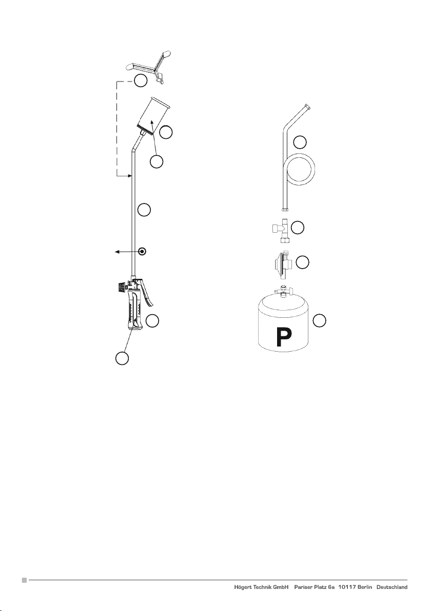
CONTENUTO-CONTENTS-CONTENTU-INHALT-CONTENIDO
1. Düse
2. Verlängerung
3. Schweißstab
OPTIONALES ZUBEHÖR
4. Hochdruckschlauch (min. 20 BAR) - Innendurchmesser ca. 8 mm. Nur zugelassene Schläuche verwenden
5. Explosionsschutzventil
6. Druckregler 0-3 BAR
7. Propangasflasche
8. Kippständer
KENNZEICHNUNGEN
9. Angabe von-Indication of-Indication de: Name des Herstellers
Zulässiges Gas (P- LPG/LPG)
Verbrauch
6
Adres producenta/ Adresse des Herstellers/ Manufacturer’s Address/ Адрес производителя
GTV Poland S.A., ul. Przejazdowa 21, 05-800 Pruszków, www.hoegert.com
Page 7
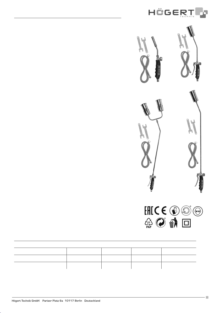
RU
ИНСТРУКЦИЯ ПО ОБСЛУЖИВАНИЮ
КОМПЛЕКТ ДЛЯ ГАЗОВОЙ СВАРКИ
HT2C511, HT2C512, HT2C513, HT2C514
1. Убедитесь, что кран выдувной трубы плотно закрыт. Момент закрытия
маховика должен составлять 0,3 Н/м.
2. Подсоедините трубку к резаку с помощью соответствующих гаечных ключей.
3. Подсоедините шланг к регулятору давления, а затем к крану. ВНИМАНИЕ:
Проверьте наличие прокладки между регулятором давления и краном
баллона. При наличии, между трубой и регулятором давления должен быть
установлен противовзрывной клапан.
4. Откройте кран баллона.
5. Проверьте уплотнения между резаком и трубкой и между трубкой и
цилиндром с помощью детектора пузырьков воздуха (тип арт. 1726).
6. В случае утечки закройте баллон и снова проверьте затяжку и герметичность.
Если проблема сохраняется, обратитесь к дилеру.
7. Умеренно (на 1/2 оборота) откройте маховик крана против часовой стрелки
и поднесите пламя к соплу или нажмите кнопку розжига (для моделей с
пьезорозжигом).
8. Затем полностью откройте кран, чтобы получить максимальную мощность
резака.
9. По окончании работы всегда закрывайте сначала кран баллона, затем кран
резака.
10. При замене баллонов всегда работайте в хорошо проветриваемых
помещениях, вдали от источников тепла и открытого огня. Затем повторите
действия, начиная с шага 1.
ПРЕДУПРЕЖДЕНИЯ
11. Используйте только с газом пропаном при давлении от 0,5 до 3 БАР.
12. Не используйте регуляторы с фиксированной настройкой для бытового
использования, так как создаваемое давление недостаточно.
13. Используйте только на открытом воздухе в хорошо проветриваемых местах.
14. Если насадка горячая, храните ее в безопасном месте вдали от
легковоспламеняющихся материалов.
15. Любые работы с оборудованием должны выполняться специализированным
персоналом, которому производитель выдал соответствующие разрешения.
Используйте только оригинальные запасные части.
16. Рекомендуется использовать резак с антивзрывным клапаном.
HT2C511
HT2C512
Таблица потребления
Сопло
Давление 20 30 45 60
0, 5 БАР 0.12 кг/ч 0.39 кг/ч 0.85 кг/ч 2.20 кг/ч
3 БАР 0.31 кг/ч 1.00 кг/ч 2.25 кг/ч 5.70 кг/ч
Adres producenta/ Adresse des Herstellers/ Manufacturer’s Address/ Адрес производителя
GTV Poland S.A., ul. Przejazdowa 21, 05-800 Pruszków, www.hoegert.com
HT2C513
HT2C514
7
Page 8
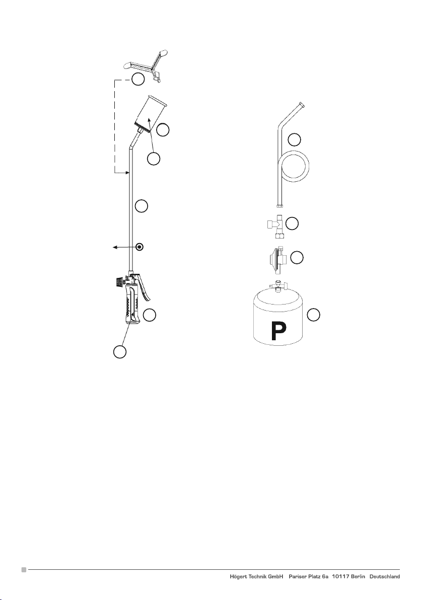
8
1
4
9
2
5
6
3
7
10
СОДЕРЖАНИЕ
1. Сопло
2. Расширение
3. Резак
ДОПОЛНИТЕЛЬНЫЕ АКСЕССУАРЫ
4. Шланг высокого давления (мин. 20 BAR) - внутренний диаметр ок. 8 мм Используйте только одобренные шланги
5. Антивзрывной клапан
6. Регулятор давления 0-3 BAR
7. Пропановый баллон
8. Подставка
МАРКИРОВКА
9. Указание на: Имя застройщика
Допустимые к использованию газы (P- LPG/LPG)
Потребление
8
Adres producenta/ Adresse des Herstellers/ Manufacturer’s Address/ Адрес производителя
GTV Poland S.A., ul. Przejazdowa 21, 05-800 Pruszków, www.hoegert.com
Page 9
FR
INSTRUCTIONS
KIT DE SOUDAGE AU GAZ
HT2C511, HT2C512, HT2C513, HT2C514
Merci d’avoir acheté notre produit. Le produit, fabriqué conformément à
des normes élevées, offrira des années de fonctionnement sans problème,
à condition de l’utiliser conformément à la notice et de l’entretenir correctement.
1. Assurez-vous que le robinet du brûleur est bien fermé. Le couple de
fermeture du bouton du robinet doit être de 0,3 N/m.
2. Raccordez le tuyau au brûleur à l'aide des clés appropriées.
3. Raccordez le tuyau au régulateur de pression, puis à la valve.
REMARQUE: Vérifier qu'entre le régulateur de pression et la valve il y
a un joint. Une éventuelle valve antidéflagrante doit être installée entre
le tuyau et le régulateur de pression.
4. Ouvrir le robinet de la bouteille.
5. Vérifier les joints entre la buse et le tube et entre le tube et le régulateur
de pression avec un détecteur de bulles d'air (par exemple notre Art.
1726).
6. En cas de fuite, fermer la bouteille et revérifier l'étanchéité et les joints.
Si le problème persiste, contactez votre revendeur.
7. Ouvrez modérément (1/2 tour) le bouton du robinet dans le sens
inverse des aiguilles d'une montre et réglez la flamme sur la buse ou
appuyez sur le bouton d'allumage (pour les modèles avec allumage
piézoélectrique).
8. Puis, ouvrez complètement le robinet pour obtenir la puissance
maximale du brûleur.
9. Une fois le travail terminé, fermez toujours d'abord le robinet de la
bouteille, puis le robinet du brûleur.
10. Lors du changement des bouteilles, travaillez toujours dans un
endroit bien aéré, loin des sources de chaleur et des flammes nues.
Répétez ensuite les opérations à partir du point 1.
AVERTISSEMENTS
11. Utiliser uniquement avec du gaz propane à une pression de 0,5 à 3
bars.
12. Ne pas utiliser avec des détendeurs à calibrage fixe pour un usage
domestique car la pression fournie est insuffisante. la pression
fournie est insuffisante.
13. Utiliser uniquement à l'extérieur dans des zones bien ventilées.
14. Après utilisation, la buse est chaude, Rangez-la dans un endroit sûr,
loin des matériaux inflammables.
15. Toute intervention sur l'appareil doit être effectuée par du personnel spécialisé et autorisé par le fabricant. Utilisez uniquement
des pièces de rechange d'origine.
16. Nous recommandons l'utilisation d'un brûleur avec une valve antidéflagrante.
HT2C511
HT2C513
HT2C512
HT2C514
Tableau de consommation
Buse
Pression 20 30 45 60
0. 5 BAR 0.12 kg/h 0.39 kg/h 0.85 kg/h 2.20 kg/h
3 BAR 0.31 kg/h 1.00 kg/h 2.25 kg/h 5.70 kg/h
Adres producenta/ Adresse des Herstellers/ Manufacturer’s Address/ Адрес производителя
GTV Poland S.A., ul. Przejazdowa 21, 05-800 Pruszków, www.hoegert.com
9
Page 10
8
1
4
9
2
5
6
3
7
10
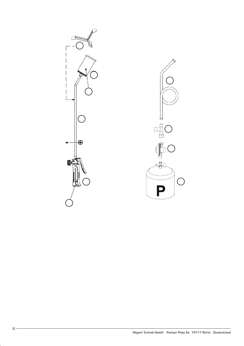
KOMPONENTY-CONTENTS-CONTENTU-INHALT-CONTENIDO
1. Buse
2. Tube d’extension
3. Brûleur
ACCESSOIRES SUPPLÉMENTAIRES
4. Tuyau haute pression (min. 20 BAR) - diamètre interne environ 8 mm. N’utilisez que des tuyaux homologués
5. Valve antidéflagrante
6. Régulateur de pression 0-3 bars
7. Bouteille de propane
8. Support
MARQUAGE
9. Oznaczenie-Indication of-Indication sur: Nom du fabricant
Gaz autorisés (P-GPL/LPG)
Consommation
10
Adres producenta/ Adresse des Herstellers/ Manufacturer’s Address/ Адрес производителя
GTV Poland S.A., ul. Przejazdowa 21, 05-800 Pruszków, www.hoegert.com
Page 11
IT
ISTRUZIONI
KIT SALDATURA GAS
HT2C511, HT2C512, HT2C513, HT2C514
1. Assicurarsi che ii rubinetto del cannello sia ben chiuso. II momenta
torcente di chiusura del volantino dovra essere 0,3 N/m.
2. Collegare ii tuba al cannello utilizzando apposite chiavi.
3. Collegare ii tuba al regolatore di pressione e successivamente al
rubinetto. ATTENZIONE: verificare la presenza deIla guarnizione fra
ii regolatore di pressione ed ii rubinetto della bombola. Ove presente,
la valvola antiscoppio deve essere pasta tra ii tubae ii regolatore di
pressione.
4. Aprire ii rubinetto della bombola.
5. Verificare le tenute tra cannello e tubae tra tubae bornbola con
apposite rilevatore a belle (tipo ns. art. 1726).
6. In caso di perdite chiudere la bornbola e verificare nuovamente i
serraggi e le tenute. Se ii problema persiste, rivolgersi al proprio
rivenditore.
7. Aprire moderatamente (1/2 giro) ii volantino del rubinetto in senso
antiorario e accostare una fiamma al beccuccio, oppure agire sul
pulsante di accensione ( per i modelli con accensione piezoelettrica).
8. Aprire quindi ii rubinetto completamente per ottenere la massima
potenzialitB. dal vostro cannello.
9. Terminato ii lavoro chiudere sempre prima ii rubinetto della bombola,
quindi ii rubinetto del cannello.
10. In caso di sostituzione delta bombola, operare sempre in zone ben
ventilate e lontano da fonti di calore e fiamme libere. Ripetere poi le
operazioni dal punto 1.
AVVERTENZE
11. Utilizzare solo con gas propano ad una pressione compresa tra 0,5
e 3 BAR.
12. Non utilizzare con regolatori a taratura fissa per uso domestico in
quanta la pressione erogata e insufficiente.
13. Utilizzare solo all'aperto a in luoghi ben ventilati.
14. Al termine del lavoro ii beccuccio sara motto caldo, riporlo in un luogo
sicuro lontano da materiali infiammabili.
15. Eventuali interventi sull'apparecchiatura dovranno essere effettuati
da personale specializzato e autorizzato dal Costruttore. Utilizzare
solo parti di ricambio originali.
16. Si consiglia l'utilizzo del cannello con valvola antiscoppio.
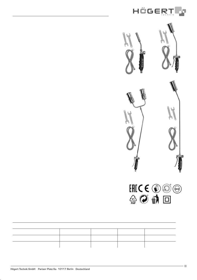
HT2C511
HT2C513
HT2C512
HT2C514
Tabella consumi
Beccuccio
Pressione 20 30 45 60
0. 5 BAR 0.12 kg/h 0.39 kg/h 0.85 kg/h 2.20 kg/h
3 BAR 0.31 kg/h 1.00 kg/h 2.25 kg/h 5.70 kg/h
Adres producenta/ Adresse des Herstellers/ Manufacturer’s Address/ Адрес производителя
GTV Poland S.A., ul. Przejazdowa 21, 05-800 Pruszków, www.hoegert.com
11
Page 12
8
1
4
9
2
5
6
3
10
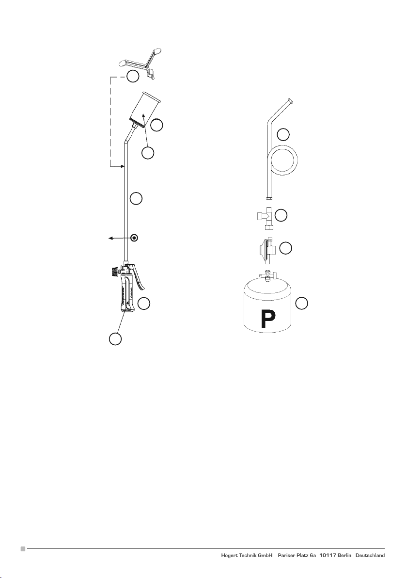
CONTENUTO-CONTENTS-CONTENTU-INHALT-CONTENIDO
1. Beccuccio
2. Prolunga
3. Cannello
ACCESSORI OPZIONALI
4. Tuba per alta pressione (min 20 BAR) - diam. interno 8 mm ca. Utilizzare unicamente tubi omologati
5. Valvola antiscoppio
6. Regolatore di pressione 0-3 BAR
7. Bombola Propan
8. Cavalletto
MARCATURE
9. lndicazione di-Indication of-Indication de: Nome del Costruttore
Gas ammissibili (P- GPL/LPG)
Consumo
7
12
Adres producenta/ Adresse des Herstellers/ Manufacturer’s Address/ Адрес производителя
GTV Poland S.A., ul. Przejazdowa 21, 05-800 Pruszków, www.hoegert.com
 Loading...