

Page 1
PL
INSTRUKCJA OBSŁUGI
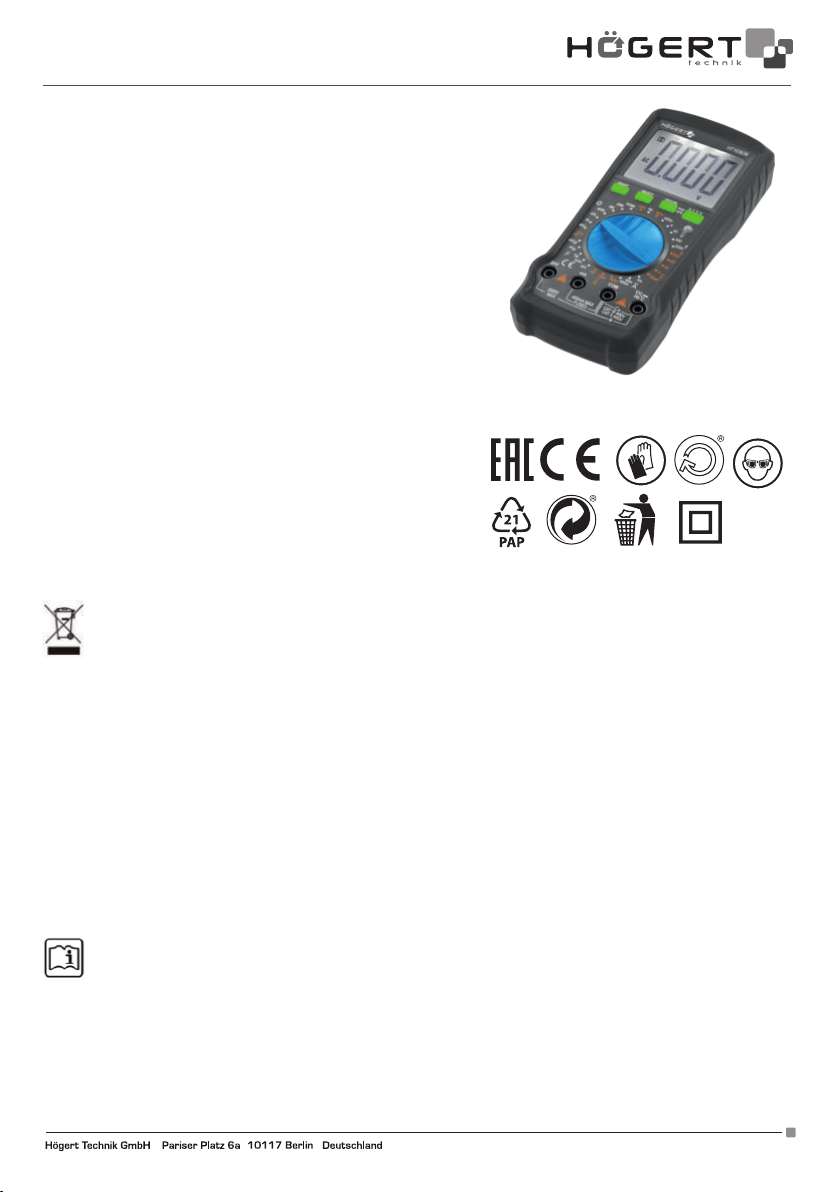
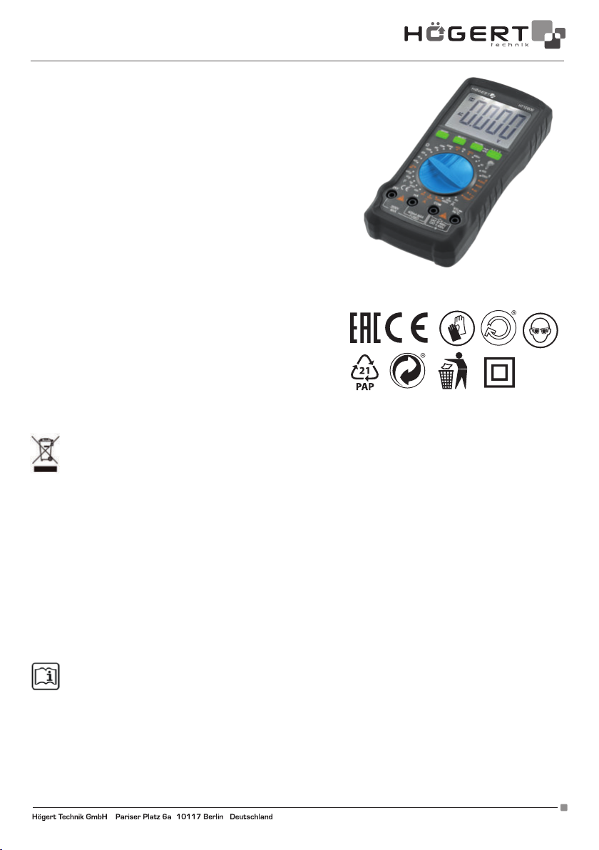
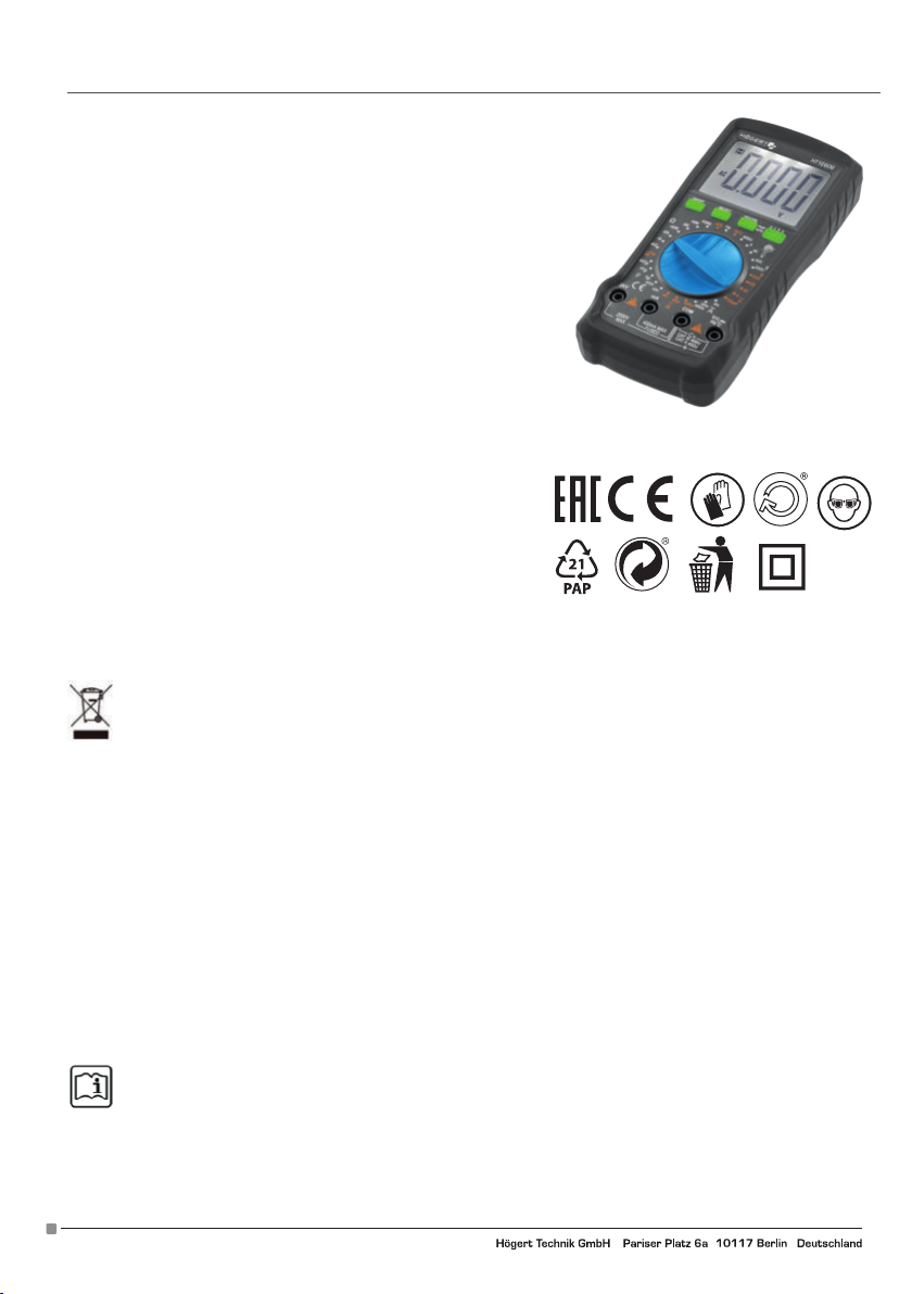
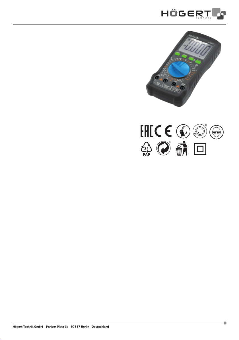
CYFROWY MIERNIK UNIWERSALNY HT1E606
Dziękujemy za zakup naszego produktu. Wyprodukowany zgodnie z
wysokim standardem produkt zapewni lata bezproblemowej pracy pod
warunkiem stosowania zgodnie z instrukcją i odpowiednio utrzymany.
SPIS TREŚCI
1. Informacje ogólne
2. Ogólne warunki bezpieczeństwa
3. Opis i funkcje
4. Pomiary
4.1. Pomiar indukcyjny NCV
4.2. Pomiar napięcia U DC/AC
4.3. Pomiar natężenia I DC/AC
4.4. Pomiar Oporności
4.5. Test pojemności
4.6. Test częstotliwości
4.7. Test temperatury
4.8. Test ciągłości
4.9. Test tranzystora hFE
5. Specyfikacja
5.1. Specyfikacja techniczna
5.2. Specyfikacja elektryczna
6. Konserwacja
6.1. Wymiana baterii
6-2. Wymiana bezpiecznika
6-3. Konserwacja
OCHRONA ŚRODOWISKA
Symbol wskazujący na selektywne zbieranie zużytego sprzętu elektrycznego i elektronicznego. Zużyte urządzenia
elektryczne są surowcami wtórnymi – nie wolno wyrzucać ich do pojemników na odpady domowe, ponieważ zawierają
substancje niebezpieczne dla zdrowia ludzkiego i środowiska! Prosimy o aktywną pomoc w oszczędnym gospodarowaniu
zasobami naturalnymi i ochronie środowiska naturalnego przez przekazanie zużytego urządzenia do punktu składowania
zużytych urządzeń elektrycznych. Aby ograniczyć ilość usuwanych odpadów konieczne jest ich ponowne użycie, recykling lub odzysk
w innej formie.
1. INFORMACJE OGÓLNE
Urządzenie jest przeznaczone do użytku zarówno w prywatnych gospodarstwach domowych jak i zastosowaniach komercyjnych.
Multimetr cyfrowy HT1E606 to innowacyjny, wydajny, niezawodny, w pełni funkcjonalny przyrząd zasilany bateriami, z funkcją
pomiaru napięcia prądu stałego i zmiennego aż do 2000V, pomiaru bezdotykowego NCV oraz temperatury, z dużym ekranem LCD
pokazującym 4000 znaków.
Miernik jest wyposażony w obwód zabezpieczający przed przeciążeniem, który może być używany do pomiaru napięcia stałego i przemiennego, prądu przemiennego i stałego, rezystancji, pojemności, częstotliwości, przewodów pod napięciem, napięcia akumulatora,
bezdotykowego wykrywania napięcia prądu zmiennego NCV, ciągłość diod i obwodów.
Wszelkie inne sposoby użytkowania nie są zamierzone i mogą prowadzić do uszkodzenia mienia lub nawet obrażeń ciała. Urządzenie
należy używać wyłącznie zgodnie z niniejszą instrukcją obsługi. Producent nie ponosi żadnej odpowiedzialności za uszkodzenia
spowodowane użytkowaniem niezgodnym z przeznaczeniem. Urządzenie nie jest przyrządem pomiarowym w rozumieniu ustawy
“Prawo o pomiarach”.
2. OGÓLNE WARUNKI BEZPIECZEŃSTWA
W zakresie właściciela i użytkownika jest przeczytanie, zrozumienie i przestrzeganie poniższych zasad:
WAŻNE: Proszę przeczytać tą instrukcję uważnie. proszę zwrócić szczególną uwagę na wymogi bezpiecznego użytkowania,
ostrzeżenia i uwagi. używać produkt prawidłowo i z uwagą do celów, do których został przeznaczony. nieprzestrzeganie tego
może spowodować uszkodzenie i/lub uszczerbek zdrowia i spowoduje utratę gwarancji. proszę przechowywać instrukcję w
bezpiecznym miejscu w celu dalszego używania. przekazując urządzenie innej osobie, oddaj jej także instrukcję obsługi.
• Proszę wykorzystywać urządzenie jedynie dla celu, jaki został przewidziany dla urządzenia.
• Proszę trzymać urządzenie z daleka od ciepła, bezpośredniego promieniowania słonecznego, wilgoci (w żadnym wypadku nie
zanurzać w substancjach płynnych) oraz ostrych krawędzi. Proszę nie obsługiwać urządzenia wilgotnymi dłońmi.
• Pracującego urządzenia nie należy pozostawiać bez nadzoru. Przed opuszczeniem pomieszczenia urządzenie należy zawsze
wyłączyć.
• Należy regularnie sprawdzać, czy urządzenie nie jest uszkodzone. W razie wykrycia uszkodzenia należy przestać korzystać z
urządzenia.
Adres producenta/ Adresse des Herstellers/ Manufacturer’s Address/ Адрес производителя
GTV Poland Sp. z o.o. Sp. k., ul. Przejazdowa 21, 05-800 Pruszków www.hoegert.com
1
Page 2
• Dla bezpieczeństwa dzieci proszę nie zostawiać swobodnie dostępnych części opakowania (torby plastikowe, kartony, styropian,
itp.).
OSTRZEŻENIE
Nie pozwalaj dzieciom bawić się folią. Niebezpieczeństwo uduszenia!
To urządzenie nie jest przeznaczone do użytku przez osoby z ograniczonymi zdolnościami fizycznymi, sensorycznymi lub umysłowymi lub brakiem doświadczenia i / lub umiejętności, chyba że takim osobom towarzyszą i są nadzorowane przez osoby odpowiedzialne
za ich bezpieczeństwo lub otrzymały precyzyjne instrukcje użytkowania tego urządzenia i zrozumiały wynikające z tego ryzyko. Dzieci
mogą korzystać z tego urządzenia tylko w wieku powyżej 8 i pod nadzorem osoby odpowiedzialnej za ich bezpieczeństwo lub jeśli
otrzymały instrukcje użytkowania tego urządzenia i zrozumiały wynikające z tego ryzyko. Dzieci nie mogą bawić się tym urządzeniem.
INFORMACJE DOTYCZĄCE BEZPIECZEŃSTWA
Multimetr cyfrowy HT1E606 został zaprojektowany zgodnie z dyrektywą IEC61010-1 400 V (CATIII) i poziomem zanieczyszczenia 2.
Aby zapewnić prawidłowe i bezpieczne użytkowanie miernika, należy uważnie przeczytać instrukcję obsługi.
• Nie mierzyć napięcia, które przekracza zakres pomiarowy określony dla tego miernika.
• Pomimo wewnętrznego obwodu ochronnego dla pola pomiaru rezystancji, NIE należy dodawać napięcia 100 V lub więcej do zacisku
wejściowego w polu pomiaru rezystancji.
• Sprawdź poprawność przyłączenia sond.
• Unikaj używania miernika w bezpośrednim świetle słonecznym lub ekstremalnie wysokich temperaturach, o ile to możliwe.
• Unikaj ryzyka porażenia prądem podczas pomiaru napięć przekraczających 30 V AC lub 60 V DC.
• Przed pomiarem prądu należy wyłączyć zasilacz i odłączyć go od obwodu przed pomiarem.
• Podczas wymiany baterii zwracaj uwagę na biegunowość.
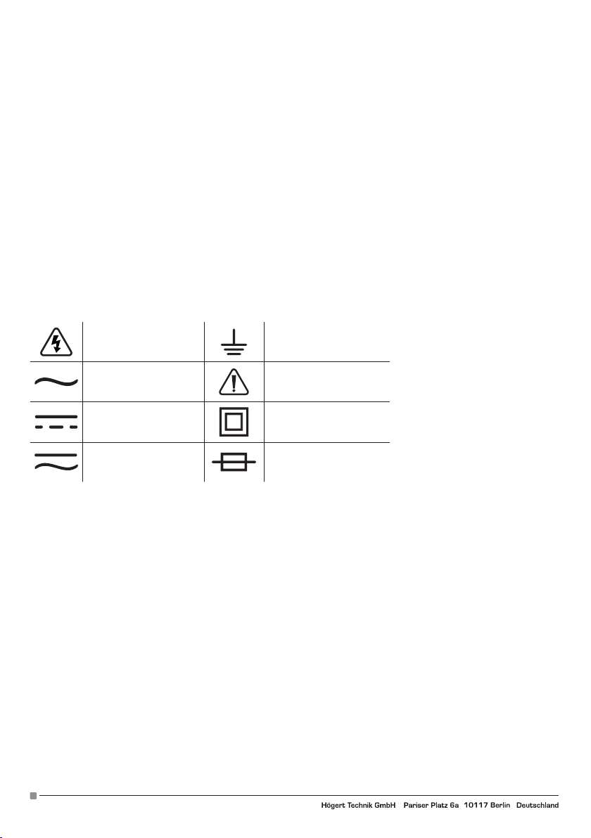
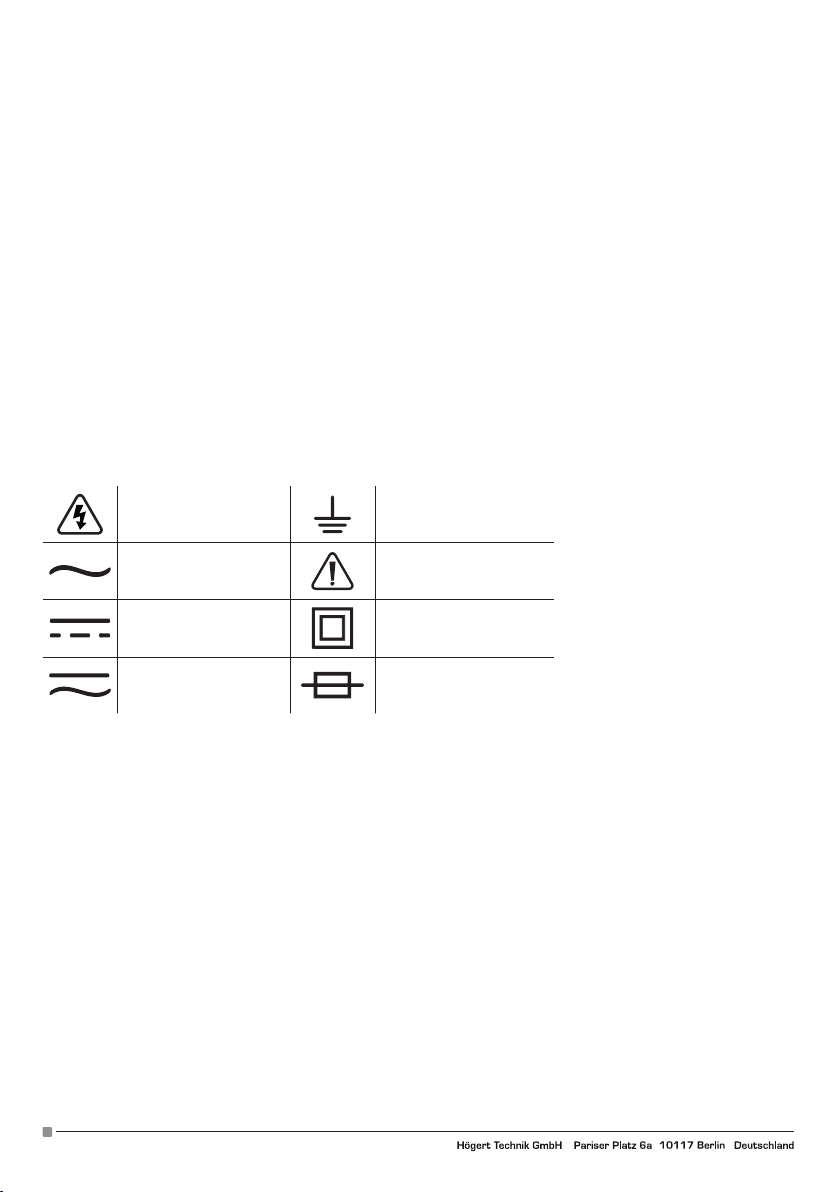
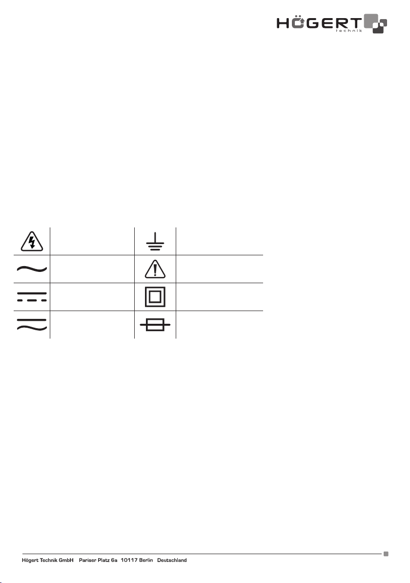
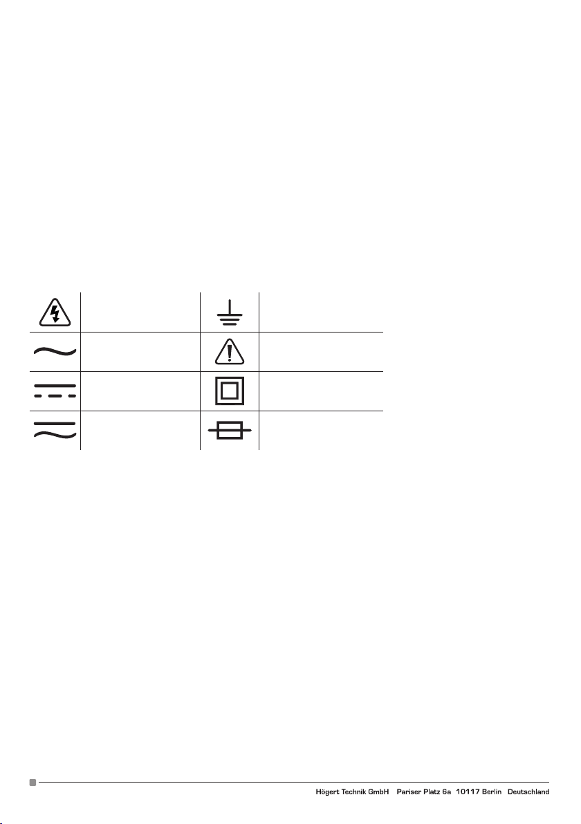
SYMBOLE ELEKTRYCZNE:
Niebezpieczeństwo
wysokiego napięcia.
Uziemienie
Prąd przemienny AC Ostrzeżenie
Prąd stały DC Podwójna izolacja
Prąd stały lub przemienny
DC/AC
Bezpiecznik
3. OPIS I FUNKCJE
1. ON / OFF – włączanie / wyłączanie urządzenia;
2. SELECT - Naciśnij przycisk „SELECT”, aby przełączyć funkcję i jednostkę miary;
3. HOLD / BL – HOLD by zatrzymać odczyt podczas pomiaru, możesz nacisnąć przycisk „HOLD”, a następnie odczyt pomiaru zostanie
zablokowany na wyświetlaczu. Naciśnij ponownie przycisk „HOLD” , stan wstrzymania odczytu zostanie zwolniony. Przytrzymaj ten
przycisk przez około 2 sekundy, aby włączyć podświetlenie (BL - Back LIght), które wyłącza się automatycznie po 15 sekundach;
można go wyłączyć, ponownie przytrzymując przycisk.
4. POMIARY
4.1. POMIAR INDUKCYJNY NCV
1. Przekręcić pokrętło funkcji w pozycję NCV.
2. Następnie chwycić przyrząd i przybliżyć jego przód do badanego elementu.
3. Wbudowany brzęczyk będzie wydawać dźwięk gdy wewnętrzny sensor wykryje prąd zmienny AC w pobliżu. Im silniejszy prąd tym
szybsze brzęczenie, a centralna dioda LED będzie migać.
4.2. POMIAR NAPIĘCIA U DC/AC > 1V
1. Urządzenie będzie wyświetlać wartość przy pomiarze prądu powyżej 1V;
2. Ustawić pokrętło funkcji w pożądanej pozycji. Przy pomiarze napięcia stałego wybrać odpowiedni zakres oznaczony V, a przy
pomiarze napięcia zmiennego V.
3. Wetknąć końcówkę czerwonego przewodu pomiarowego w terminal oznaczony „VΩ”, wetknąć końcówkę czarnego przewodu
pomiarowego w terminal „COM”;
4. Przyłożyć końcówki przewodów pomiarowych do mierzonych elementów,
5. Odczytać wyniki pomiaru na wyświetlaczu.
2
Adres producenta/ Adresse des Herstellers/ Manufacturer’s Address/ Адрес производителя
GTV Poland Sp. z o.o. Sp. k., ul. Przejazdowa 21, 05-800 Pruszków, www.hoegert.com
Page 3

4.3. POMIAR NATĘŻENIA PRĄDU I DC/AC
1. Wetknąć końcówkę czerwonego przewodu pomiarowego w terminal oznaczony “mA, wetknąć końcówkę czarnego przewodu
pomiarowego w terminal COM czarnego koloru.
2. Ustawić pokrętło funkcji w pożądanej pozycji. Przy pomiarze natężenia stałego wybrać odpowiedni zakres oznaczony A, a przy
pomiarze natężenia zmiennego A.
3. Przyłożyć końcówki przewodów pomiarowych do mierzonego elementu.
4. Odczytać na wyświetlaczu wartość natężenia.
4.4. POMIAR OPORNOŚCI
Aby uniknąć uszkodzenia miernika lub testowanego urządzenia, należy odłączyć zasilanie testowanego obwodu i całkowicie rozładować wszystkie kondensatory wysokiego napięcia przed pomiarem rezystancji.
1. Ustaw przełącznik funkcji na odpowiednim polu w zakresie oznaczonym „Ω”. Na początku miernik wyświetla „OL”, wskazując, że
wejście jest w obwodzie otwartym, tzn. nie podłączono żadnej rezystancji;
2. Podłącz czarną sondę odpowiednio do gniazda wejściowego „COM”, a czerwoną do gniazda wejściowego „V Ω”;
3. Użyj końcówek sondy, aby zmierzyć rezystancję badanego obwodu;
4. Odczytaj zmierzoną wartość rezystancji na wyświetlaczu.
4.5. POMIAR POJEMNOŚCI F
1. Wetknąć końcówkę czerwonego przewodu pomiarowego w terminal oznaczony „VΩ”, wetknąć końcówkę czarnego przewodu
pomiarowego w terminal „COM”;
2. Ustawić pokrętło funkcji w pożądanej pozycji w zakresie oznaczonym F;
3. Przyłożyć końcówki przewodów pomiarowych do mierzonego elementu;
4. Odczytać na wyświetlaczu wartość pojemności.
4.6. POMIAR CZĘSTOTLIWOŚCI HZ
1. Wetknąć końcówkę czerwonego przewodu pomiarowego w terminal oznaczony „VΩHz”, wetknąć końcówkę czarnego przewodu
pomiarowego w terminal „COM”;
2. Ustawić pokrętło funkcji w pozycji oznaczonej Hz;
3. Przyłożyć końcówki przewodów pomiarowych do mierzonego elementu;
4. Odczytać na wyświetlaczu wartość częstotliwości.
4.7. POMIAR TEMPERATURY TEMP
1. Do urządzenia dołączone są dodatkowe przewodu przeznaczone do pomiaru temperatury. Wetknąć końcówkę czerwonego przewodu pomiarowego w terminal oznaczony „VΩHz°C”, wetknąć końcówkę czarnego przewodu pomiarowego w terminal „COM”;
2. Ustawić pokrętło funkcji w pozycji oznaczonej TEMP;
3. Przyłożyć końcówki przewodów pomiarowych do mierzonego elementu;
4. Odczytać na wyświetlaczu wartość temperatury.
4.8. TEST CIĄGŁOŚCI
1. Wetknąć końcówkę czerwonego przewodu pomiarowego w terminal oznaczony “VΩ”, wetknąć końcówkę czarnego przewodu
pomiarowego w terminal „COM”;
2. Ustawić pokrętło funkcji w pozycję ;
3. Przyłożyć końcówki przewodów pomiarowych do mierzonych elementów, wynik pomiaru będzie wyświetlony na wyświetlaczu;
4. Wbudowany brzęczyk będzie wydawać sygnał dźwiękowy jeżeli oporność pomiędzy próbnikami będzie mniejsza niż 30 +/- 10Ω.
4.9. TEST TRANZYSTORA NPN, PNP
1. Ustawić pokrętło funkcji w pozycję „hFE”;
2. Upewnić się czy tranzystor jest typu NPN czy PNP;
3. Umieścić tranzystor odpowiednio w porcie E.B.C.;
4. Odczytać wynik na wyświetlaczu.
5. SPECYFIKACJA
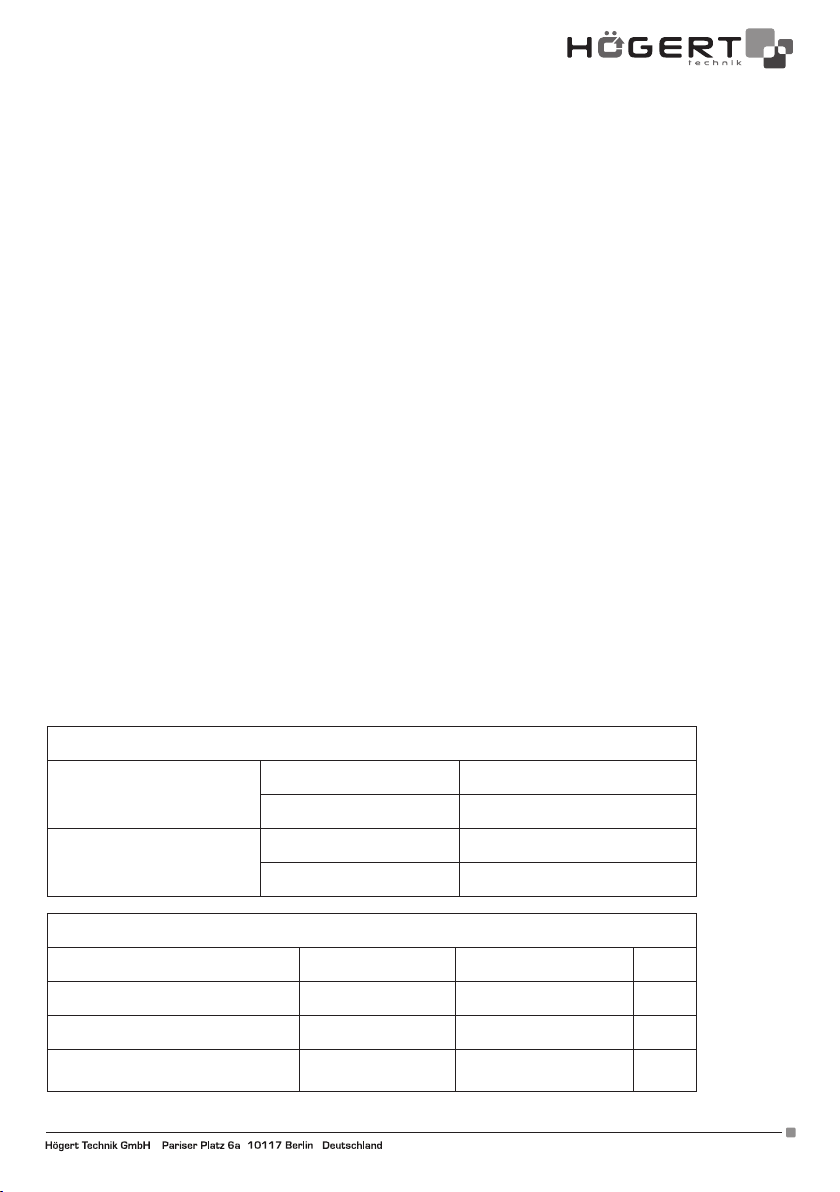
5.1. SPECYFIKACJA TECHNICZNA
Specyfikacja warunków zewnętrzynych
Temperatura 0~40°C
Użytkowanie
Wilgotność < 75%
Adres producenta/ Adresse des Herstellers/ Manufacturer’s Address/ Адрес производителя
GTV Poland Sp. z o.o. Sp. k., ul. Przejazdowa 21, 05-800 Pruszków www.hoegert.com
3
Page 4
Przechowywanie
Temperatura -10~50°C
Wilgotność < 75%
Specyfikacja techniczna
Wyświetlacz 4000 znaków Data Hold √
Materiał ABS Podświetlany wyświetlacz √
Częstotliwość próbkowania 3/s Pomiar bezdotykowy √
Wskaźnik niskiego poziomu baterii √ Auto wyłączenie √
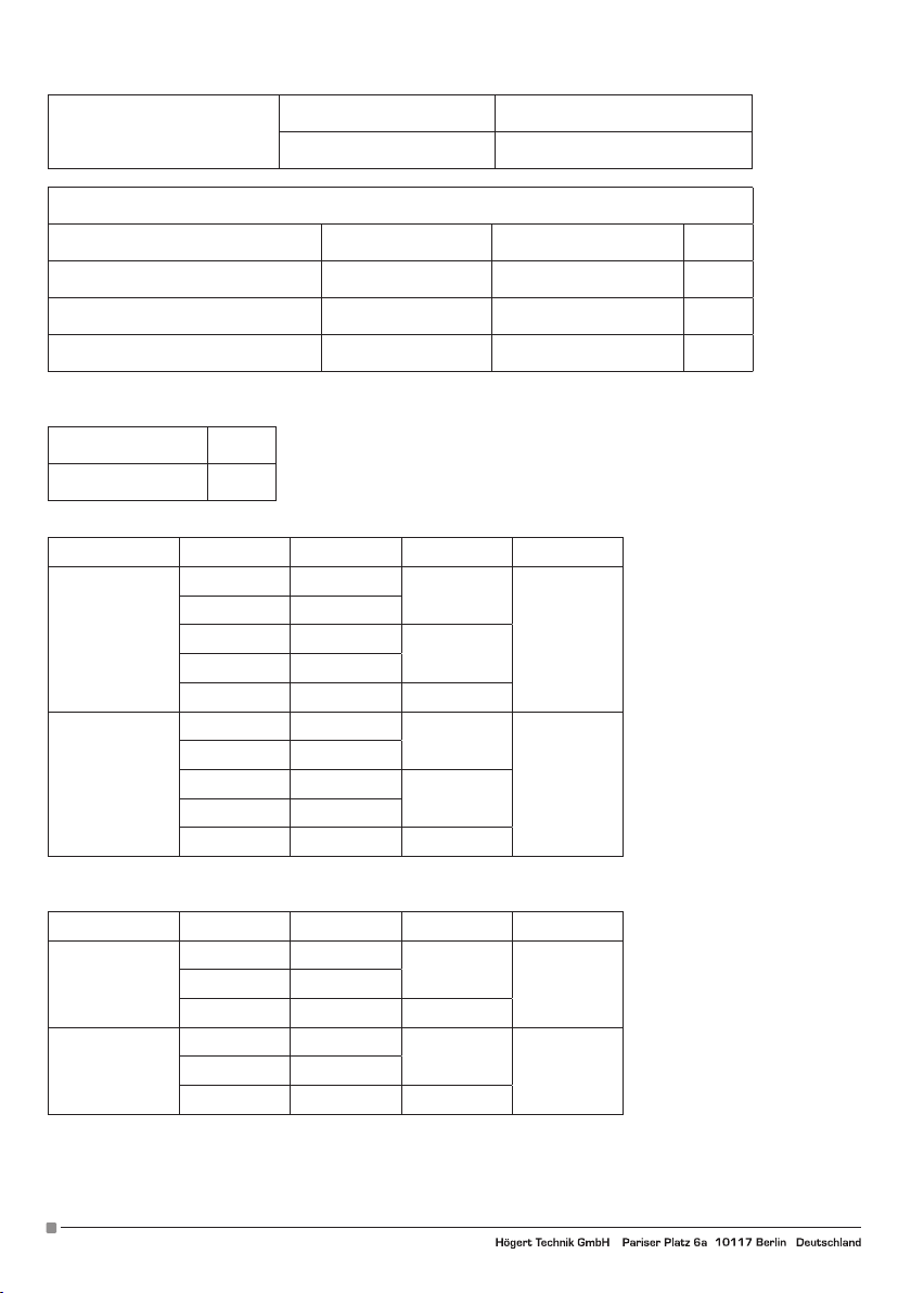
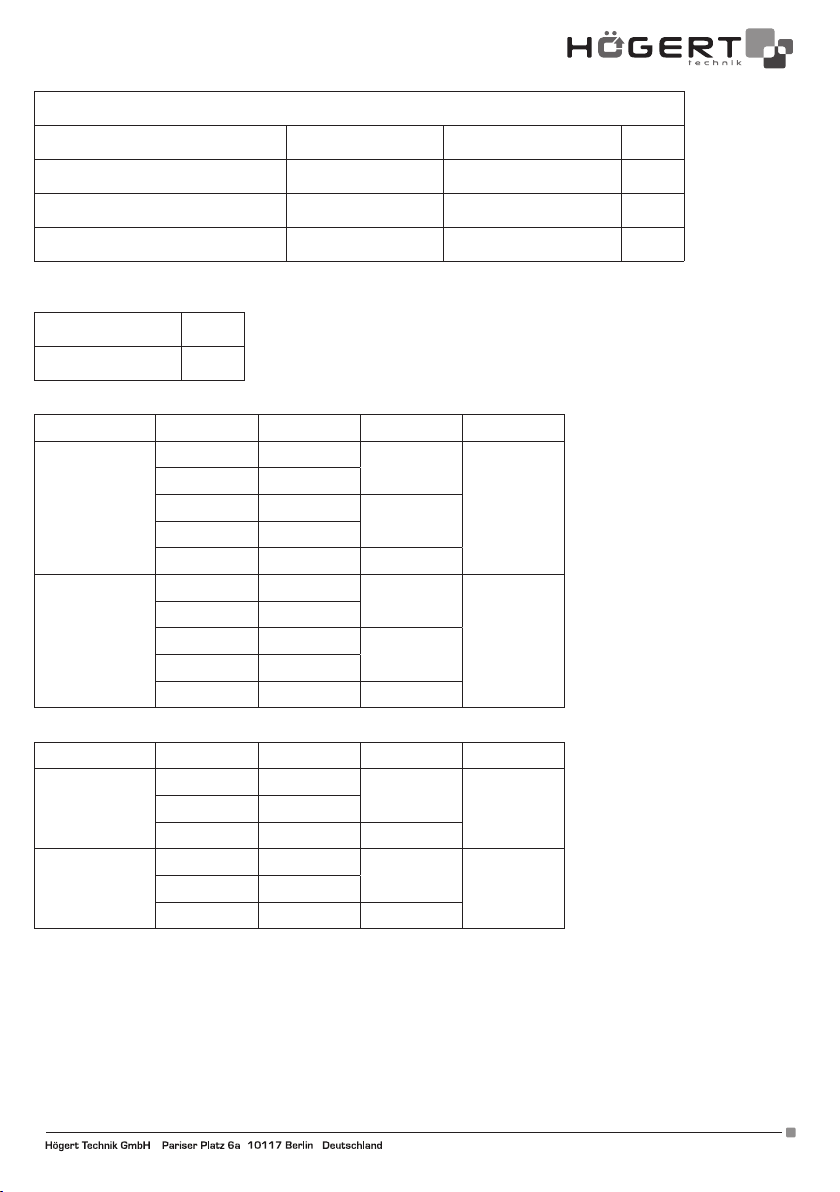
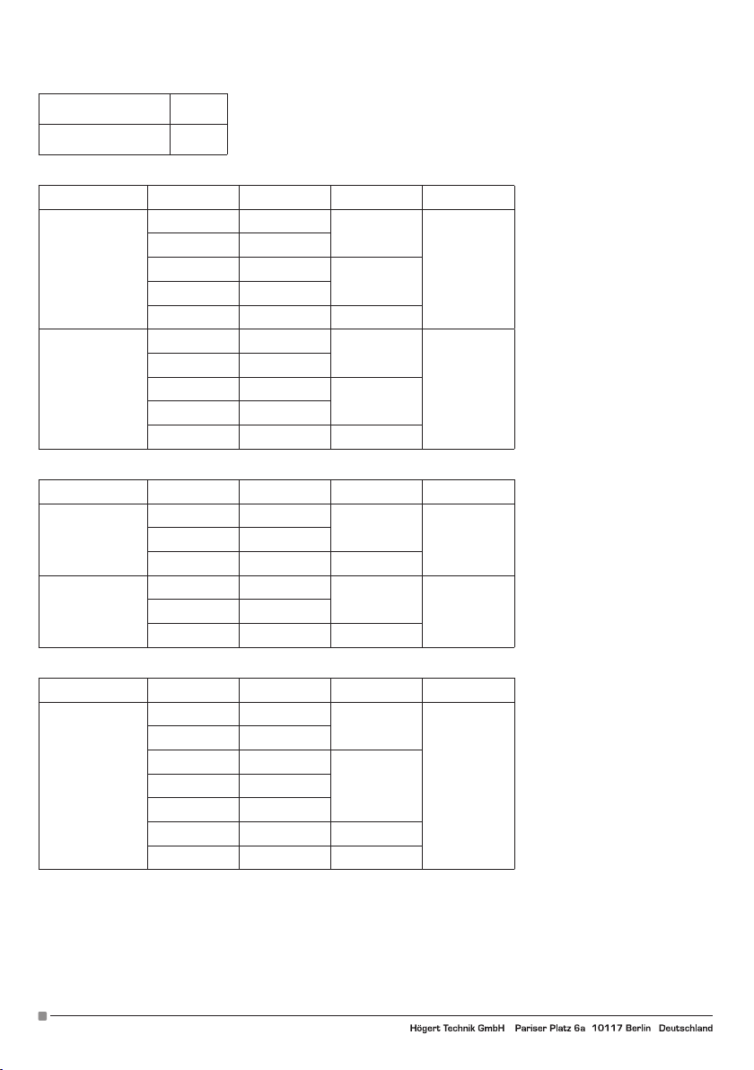
5.2 SPECYFIKACJA ELEKTRYCZNA
1. Test ciągłości i indukcyjny
Test ciągłości √
NCV √
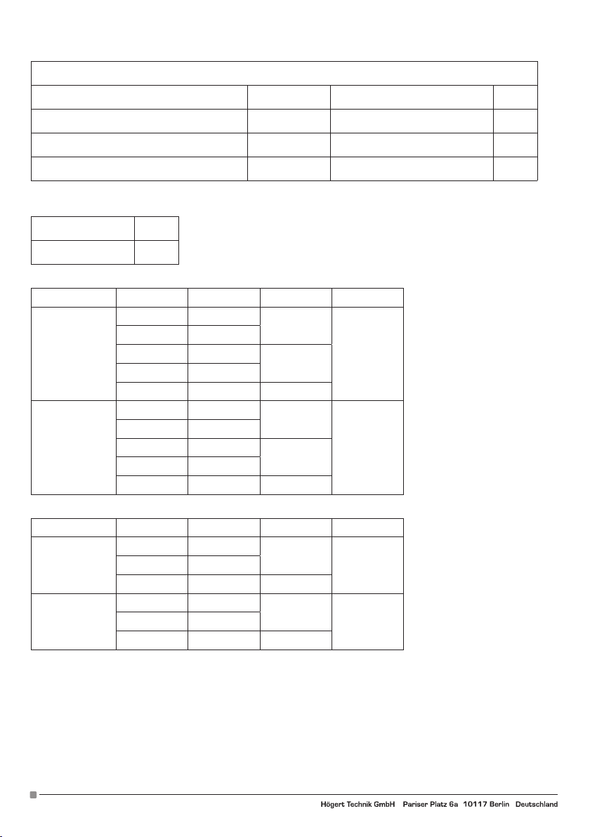
2. Napięcie U DC/AC
Funkcja Zakres Rozdzielczość Dokładność Max
Napięcie UDC
(V)
400mV 100uV
4V 1mV
40V 10mV
400V 100mV
±(0.5%+5d)
±(0.8%+5d)
2000V
2000V 1V (2.0%+5d)
Napięcie UAC
(V)
400mV 100uV
4V 1mV
40V 10mV
400V 100mV
±(0,5%+5d)
±(0,8%+5d)
2000V
2000V 1V (2.0%+5d)
3 Natężenie prądu AC/DC
Funkcja Zakres Rozdzielczość Dokładność Max
Natężenie IDC
(A)
4mA 1uA
± (1.0%+3d)
± (1.0%+3d)
400mA 100uA ± (1.0%+3d)
Natężenie IUC
(A)
4mA 1uA
±(2.0%+3d)
±(2.0%+3d)
400mA 100uA ±(2.0%+5d)
4
Adres producenta/ Adresse des Herstellers/ Manufacturer’s Address/ Адрес производителя
GTV Poland Sp. z o.o. Sp. k., ul. Przejazdowa 21, 05-800 Pruszków, www.hoegert.com
400mA40mA 10uA
400mA40mA 10uA
Page 5
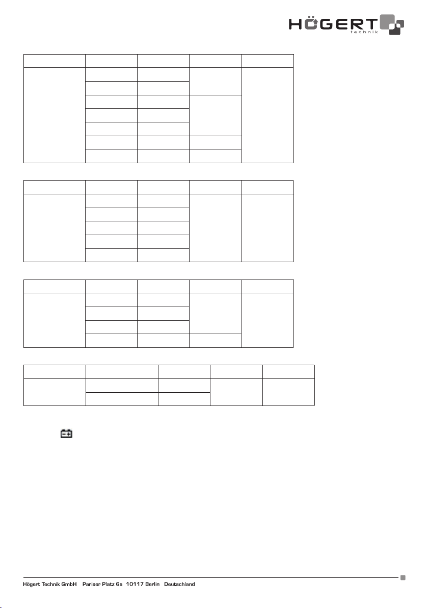
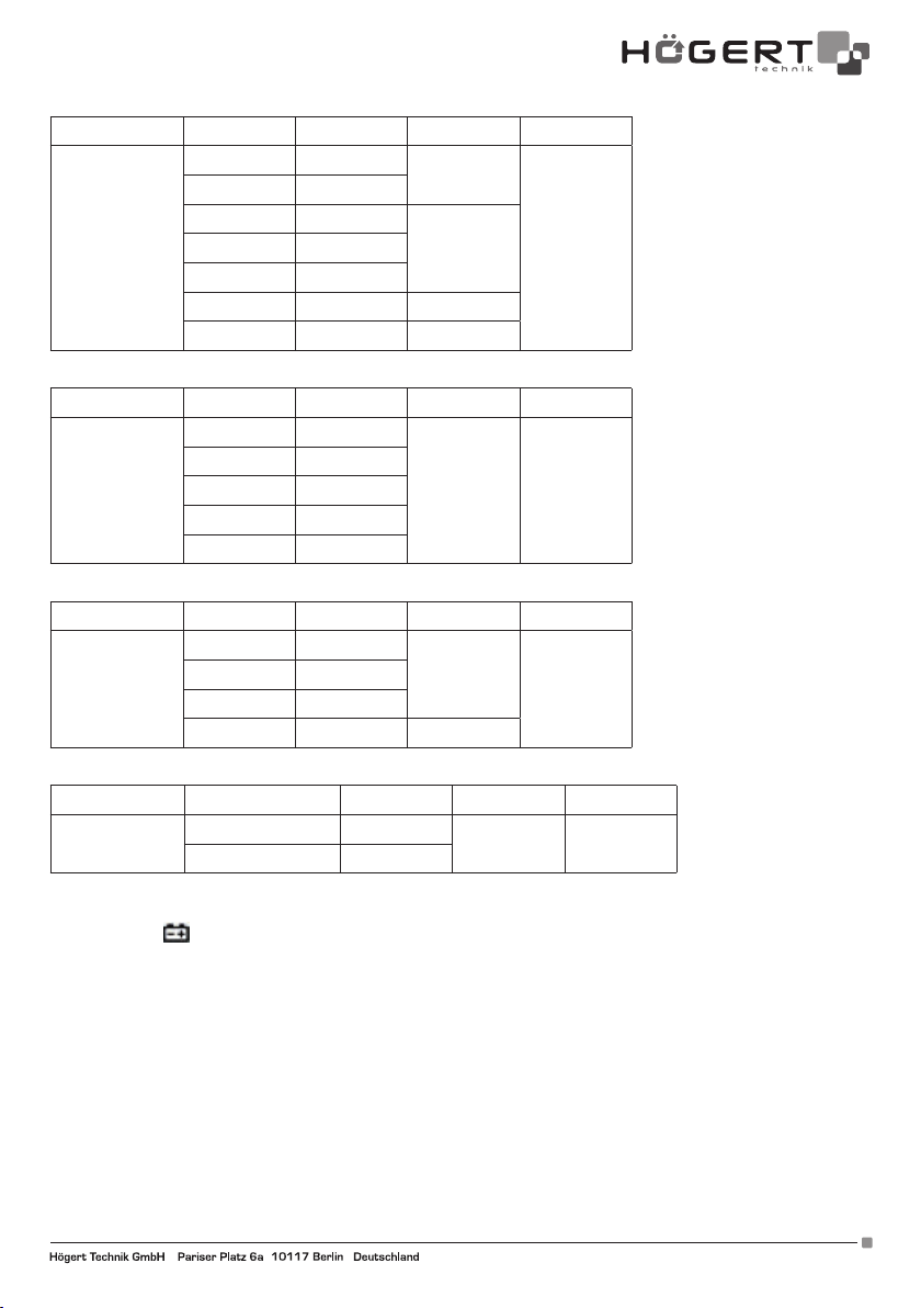
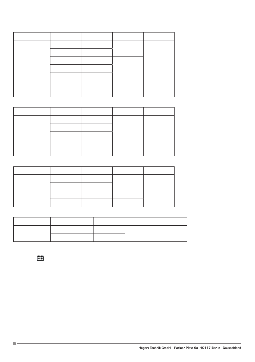
4. Oporność R
Funkcja Zakres Rozdzielczość Dokładność Max
400Ω 0.1Ω
4KΩ 1Ω
±(1.0%+5d)
40KΩ 10Ω
Oporność
±(1.0%+5d)400KΩ 100Ω
400MΩ
4MΩ 1KΩ
40MΩ 10KΩ ±(1.2%+8d)
400MΩ 100KΩ ±(4%+10d)
5. Pojemność F
Funkcja Zakres Rozdzielczość Dokładność Max
40nF 10pF
400nF 100pF
Pojemność
4uF 1nF
±(4.0%+5d) 400uF
40uF 10nF
400uF 100nF
6. Częstotliwość Hz
Funkcja Zakres Rozdzielczość Dokładność Max
4kHz 1Hz
Częstotliwość
40kH 10Hz
400kH 100Hz
±(1.5%+8d)
4MHz
4MHz 1kHz ±(1.5%+40d)
7. Temperatura
Funkcja Zakres Rozdzielczość Dokładność Max
Temperatura
-40°C~400°C 1°C
-400°C ~1000°C 1°C
±(1%+8d)
±(1.5%+15d)
1000°C
6. KONSERWACJA
6.1. Wymiana baterii
Jeśli symbol
pojawia się na wyświetlaczu LCD podczas użytkowania miernika należy wymienić baterię, aby zapobiec nieprawidło-
wemu odczytywaniu pomiarów.
1. Odłącz przewody testowe. Wyłącz zasilanie.
2. Za pomocą wkrętaka otwórz pokrywę baterii z tyłu, a następnie wyjmij baterię.
3. Umieść naładowaną baterię 9V 6F22 i załóż pokrywę.
6.2. Wymiana bezpiecznika
1. Najpierw usuń przewody testowe i wyłącz miernik.
2. Za pomocą wkrętaka otwórz tylną pokrywę, a następnie wyjmij zły bezpiecznik.
3. Włóż podobny bezpiecznik, zamknij tylną pokrywę i przykręć ją za pomocą śrubki.
6.3. Konserwacja
W razie potrzeby użyj miękkiej szmatki, aby zetrzeć powierzchnię miernika. Nie należy używać rozpuszczalników organicznych ani
materiałów ściernych, które mogą powodować korozję lub rozpuszczanie obudowy.
Adres producenta/ Adresse des Herstellers/ Manufacturer’s Address/ Адрес производителя
GTV Poland Sp. z o.o. Sp. k., ul. Przejazdowa 21, 05-800 Pruszków www.hoegert.com
5
Page 6
EN
USER’S MANUAL
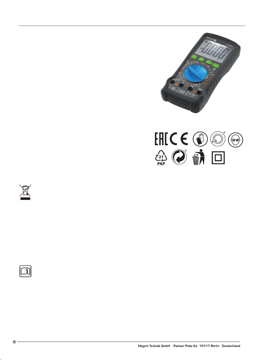
DIGITAL UNIVERSAL MULTIMETER HT1E606
Thank you for purchasing our product. Our product, manufactured to a high
standard, will provide years of trouble-free operation if used in accordance
with the instructions and properly maintained.
TABLE OF CONTENTS
1. General information
2. General safety conditions
3. Description and functions
4. Measurements
4.1. Inductive measurement NCV
4.2. Measurement of voltage U DC/AC
4.3. Measurement of voltage I DC/AC
4.4. Resistance measurement
4.5. Capacity test
4.6. Frequency test
4.7. Temperature test
4.8. Continuity test
4.9. HFE transistor test
5. Specifications
5.1. Technical Specification
5.2. Electrical specification
6. Maintenance
6.1. Battery replacement
6-2. Fuse replacement
6-3. Maintenance
Environmental protection
Symbol indicating separate collection of electrical and electronic equipment waste. Used electrical appliances are
secondary raw materials - they must not be disposed of in household waste, as they contain substances hazardous to
human health and the environment! Please actively help us to manage natural resources and protect the environment by
handing over used equipment to the waste electrical equipment storage point. To reduce the amount of waste disposed of, it
is necessary to reuse, recycle or recover it in another form.
1. GENERAL INFORMATION
The device is intended for use both in private households and for commercial purposes. The HT1E606 Digital Multimeter is an innovative, powerful, reliable, battery-powered, full-featured instrument with AC and DC voltage measurement up to 2000V, contactless
NCV and temperature measurement, with a large LCD screen showing 4000 characters.
The meter is equipped with an overload protection circuit that can be used to measure DC and AC voltage, AC and DC current,
resistance, capacity, frequency, live wires, battery voltage, non-contact NCV detection, diode and circuit continuity.
Any other use is not intended and may lead to property damage or even personal injury. Use the device only in accordance with this
manual. The manufacturer does not assume any liability for damage caused by improper use. The device is not a measuring device
within the meaning of the „Measurement Law”.
2. GENERAL SAFETY CONDITIONS
It is within the scope of the owner and user’s responsibility to read, understand and follow these rules:
IMPORTANT: Please read this manual carefully. Please pay special attention to the requirements of safe use, warnings and
notices. Use the product correctly and carefully for the purposes for which it is intended. Failure to do so may result in
damage and/or harm to health and will void the warranty. Please keep this manual in a safe place for further use. When
passing the device on to another person, also give them the manual.
• Please use the device only for the purpose intended for the device.
• Please keep the device away from heat, direct sunlight, moisture (under no circumstances immerse in liquid substances) and
sharp edges. Do not operate the device with wet hands.
• Do not leave the device running unattended. Always switch off the unit before leaving the room.
• Check regularly that the device is not damaged. If damage is detected, stop using the device.
• For the safety of children, please do not leave any freely accessible parts of the packaging (plastic bags, cartons, polystyrene, etc.).
WARNING
Don’t let the kids play with the foil. Danger of suffocation!
This device is not intended for use by persons with reduced physical, sensory or mental capabilities or lack of experience and/or
skills, unless such persons are accompanied and supervised by persons responsible for their safety or have received precise instruc-
6
Adres producenta/ Adresse des Herstellers/ Manufacturer’s Address/ Адрес производителя
GTV Poland Sp. z o.o. Sp. k., ul. Przejazdowa 21, 05-800 Pruszków, www.hoegert.com
Page 7
tions for the device usage and understand the risks involved. Children may only use this device if they are over 8 years old and under
the supervision of a person responsible for their safety or if they have received instructions for use of this device and understand the
risks involved. Children cannot play with this device.
SAFETY INFORMATION
The HT1E606 digital multimeter is designed according to the IEC61010-1 400 V (CATIII) directive and contamination level 2. To ensure
proper and safe use of the meter, read the manual carefully.
• Do not measure a voltage that exceeds the measuring range specified for this meter.
• Despite the internal protective circuit for the resistance measurement field, do NOT add 100 V or more to the input terminal in the
resistance measurement field.
• Check that the probes are connected correctly.
• Avoid using the meter in direct sunlight or extremely high temperatures, if possible.
• Avoid the risk of electric shock when measuring voltages exceeding 30 V AC or 60 V DC.
• Switch off the power supply and disconnect it from the circuit before the current measurement.
• Pay attention to polarity when replacing batteries.
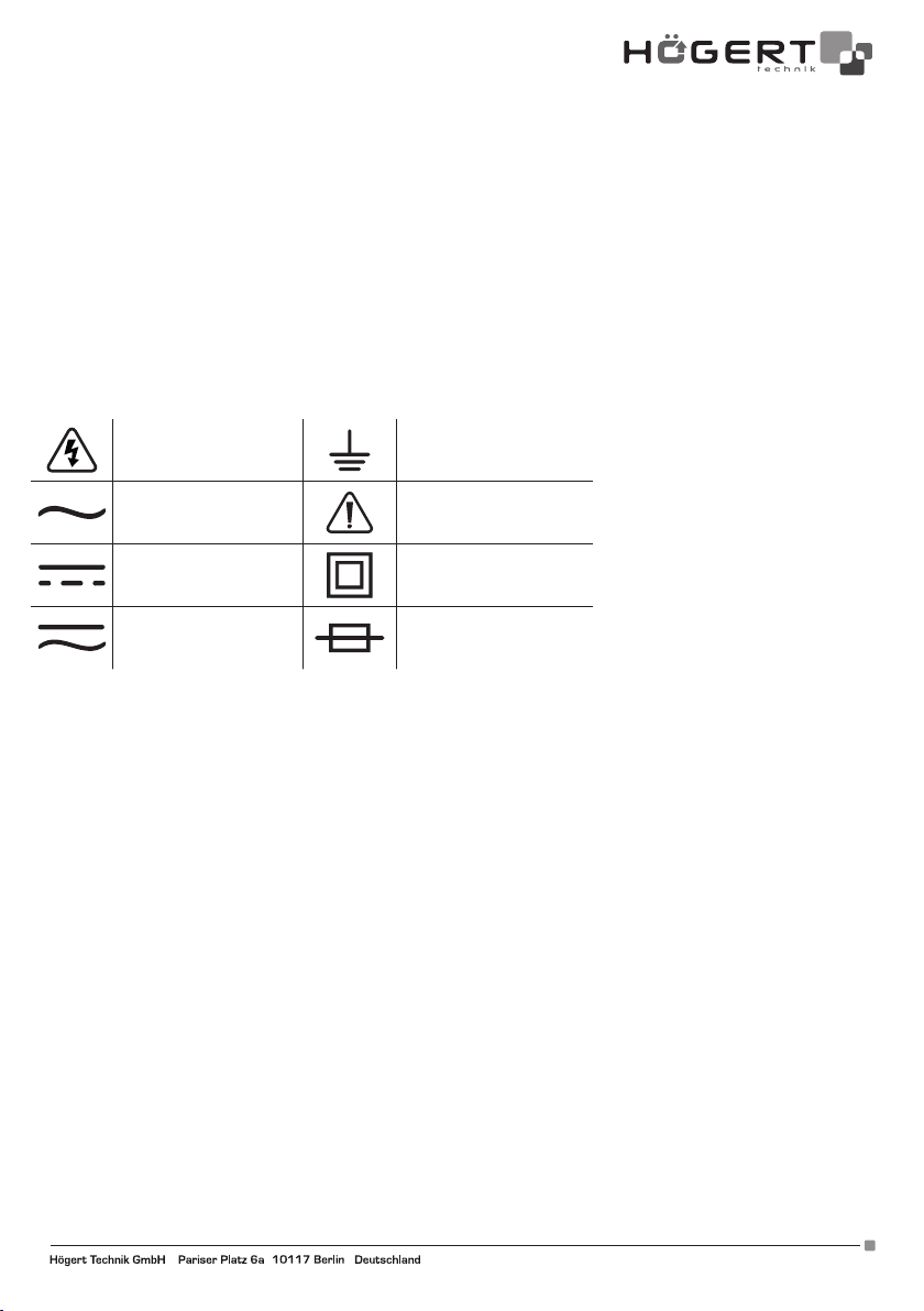
ELECTRICAL SYMBOLS:
High voltage can occur. . Ground
Alternating Current AC
Important safety
information.
Direct Current DC Double insulation
Direct or alternating
current DC/AC
Fuse
3. DESCRIPTION AND FUNCTIONS
1. ON / OFF - turn the device on / off;
2. SELECT - Press the „SELECT” button to switch the function and unit of measurement;
3. HOLD / BL – HOLD to stop the reading during the measurement, you can press the „HOLD” button, and then the measurement
reading will be locked on the display. Press the „HOLD” button again, the read pause status will be released. Hold this button down
for about 2 seconds to turn on the backlight (BL - Back LIght), which turns off automatically after 15 seconds; you can turn it off by
pressing the button again.
4. MEASUREMENTS
4.1. Inductive measurement NCV
1. Turn the function knob to the NCV position.
2. Then grasp the instrument and bring the front of the instrument closer to the test piece.
3. The built-in buzzer will beep when the internal sensor detects AC nearby. The stronger the current, the faster the buzzing and the
central LED will flash.
4.2. Voltage measurement U DC/AC (> 1V)
1. The device will display the value when measuring current above 1V;
2. Turn the function knob to the desired position. When measuring direct voltage, select the appropriate range marked V, and when
measuring alternating voltage V.
3. Insert the end of the red test lead into the terminal marked „VΩ”, insert the end of the black test lead into the „COM” terminal;
4. Put the ends of the test leads to the measured elements,
5. Read the measurements on the display.
4.3. Current measurement I DC/AC
1. Insert the end of the red test lead into the terminal marked „mA”, insert the end of the black test lead into the clack „COM” terminal;
2. Turn the function knob to the desired position. When measuring direct voltage, select the appropriate range marked V, and when
measuring alternating voltage V.
3. Put the ends of the test leads to the measured element,
4. Read the intensity value on the display.
Adres producenta/ Adresse des Herstellers/ Manufacturer’s Address/ Адрес производителя
GTV Poland Sp. z o.o. Sp. k., ul. Przejazdowa 21, 05-800 Pruszków www.hoegert.com
7
Page 8

4.4. Resistance measurement
To avoid damage to the meter or the device under test, disconnect the power supply to the circuit under test and completely discharge all high voltage capacitors before measuring the resistance.
1. Set the function switch to the appropriate field within the range marked „Ω”. At first the meter displays „OL”, indicating that the
input is in an open circuit, i.e. no resistance is connected.
2. Connect the black probe to the „COM” input socket and the red probe to the „V Ω” input socket.
3. Use the probe tips to measure the resistance of the circuit being tested.
4. Read the measured resistance value on the display.
4.5. Capacity measurement F
1. Insert the end of the red test lead into the terminal marked „VΩ”, insert the end of the black test lead into the „COM” terminal;
2. Turn the function knob to the desired position within the range marked F;
3. Put the ends of the test leads to the measured element,
4. Read the capacity value on the display.
4.6. Hz frequency measurement
1. Insert the end of the red test lead into the terminal marked „VΩHz”, insert the end of the black test lead into the „COM” terminal;
2. Turn the function knob to the position marked Hz;
3. Put the ends of the test leads to the measured element,
4. Read the frequency value on the display.
4.7. TEMP temperature measurement
1. Additional leads for temperature measurement are included with the device. Insert the end of the red test lead into the terminal
marked „VΩHz°C”, insert the end of the black test lead into the „COM” terminal;
2. Turn the function knob to the position marked TEMP;
3. Put the ends of the test leads to the measured element,
4. Read the temperature value on the display.
4.8. Continuity test
1. Insert the end of the red test lead into the terminal marked „VΩ”, insert the end of the black test lead into the „COM” terminal;
2. Set the function switch to ;
3. Put the ends of the test leads to the measured elements, the measurement result will be shown on the display;
4. The built-in buzzer will sound if the resistance between the probes is less than 30 +/- 10Ω.
4.9. NPN, PNP Transistor test
1. Set the function switch to „hFE”;
2. Make sure the transistor is of NPN or PNP type;
3. Place the transistor properly in the E.B.C port;
4. Read the result on the display.
5. SPECIFICATION
5.1. Technical Specification
Specification of external conditions
Use
Temperature 0~40°C
Humidity < 75%
Temperature -10~50°C
Storage
Humidity < 75%
Technical Specification
Display 4000 characters Data Hold √
Material ABS Backlit display √
8
Adres producenta/ Adresse des Herstellers/ Manufacturer’s Address/ Адрес производителя
GTV Poland Sp. z o.o. Sp. k., ul. Przejazdowa 21, 05-800 Pruszków, www.hoegert.com
Page 9
Sampling frequency 3/s Contactless measurement √
Low battery indication: √ Auto off √
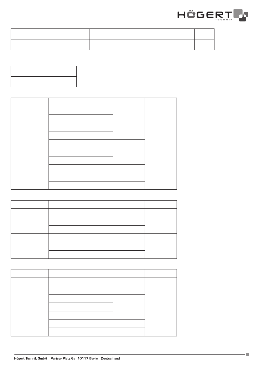
5.2. ELECTRICAL SPECIFICATION
1. CONTINUITY AND INDUCTIVE TEST
Continuity test √
NCV √
2. U DC/AC voltage
Function Range Resolution Accuracy Max.
UDC voltage
(V)
400mV 100uV
4V 1mV
40V 10mV
400V 100mV
±(0.5%+5d)
±(0.8%+5d)
2000V
2000V 1V (2.0%+5d)
UAC voltage
(V)
400mV 100uV
4V 1mV
40V 10mV
400V 100mV
±(0,5%+5d)
±(0,8%+5d)
2000V
2000V 1V (2.0%+5d)
3. Voltage I DC/AC
Function Range Resolution Accuracy Max.
IDC intensity
[A]
4mA 1uA
± (1.0%+3d)
± (1.0%+3d)
400mA40mA 10uA
400mA 100uA ± (1.0%+3d)
IUC voltage
[A]
4mA 1uA
±(2.0%+3d)
±(2.0%+3d)
400mA40mA 10uA
400mA 100uA ±(2.0%+5d)
4. Resistance R
Function Range Resolution Accuracy Max.
400Ω 0.1Ω
4KΩ 1Ω
±(1.0%+5d)
40KΩ 10Ω
Resistance
±(1.0%+5d)400KΩ 100Ω
400MΩ
4MΩ 1KΩ
40MΩ 10KΩ ±(1.2%+8d)
400MΩ 100KΩ ±(4%+10d)
Adres producenta/ Adresse des Herstellers/ Manufacturer’s Address/ Адрес производителя
GTV Poland Sp. z o.o. Sp. k., ul. Przejazdowa 21, 05-800 Pruszków www.hoegert.com
9
Page 10
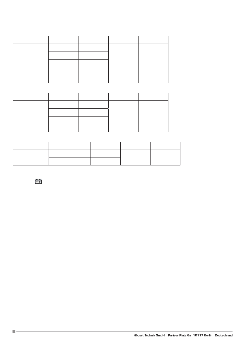
5. Capacity F
Function Range Resolution Accuracy Max.
40nF 10pF
400nF 100pF
Capacity
4uF 1nF
±(4.0%+5d) 400uF
40uF 10nF
400uF 100nF
6. . Frequency Hz
Function Range Resolution Accuracy Max.
4kHz 1Hz
Frequency
40kH 10Hz
400kH 100Hz
±(1.5%+8d)
4MHz
4MHz 1kHz ±(1.5%+40d)
7. Temperature
Function Range Resolution Accuracy Max.
Temperature
-40°C~400°C 1°C
-400°C ~1000°C 1°C
±(1%+8d)
±(1.5%+15d)
1000°C
6. MAINTENANCE
6-1. Battery replacement
If the symbol
appears on the LCD while using the meter, replace the battery to prevent incorrect reading of measurements.
1. Disconnect the test wires. Turn off the power.
2. Use a screwdriver to open the battery cover on the back, and then remove the battery.
3. Place the charged 9V 6F22 battery and replace the cover.
6.2. Fuse replacement
1. First remove the test lines and turn off the meter.
2. Use a screwdriver to open the rear cover, then remove the faulty fuse.
3. Insert a similar fuse, move the rear cover and fix it with screws.
6.3. Maintenance
If necessary, use a soft cloth to wipe the surface of the meter. Do not use organic solvents or abrasive materials that may corrode or
dissolve the case.
10
Adres producenta/ Adresse des Herstellers/ Manufacturer’s Address/ Адрес производителя
GTV Poland Sp. z o.o. Sp. k., ul. Przejazdowa 21, 05-800 Pruszków, www.hoegert.com
Page 11
DE
BENUTZERHANDBUCH
UNIVERSELL DIGITAL MESSGERAT HT1E606
Vielen Dank, dass Sie sich für unser Produkt entschieden haben. Dieses
Produkt wurde nach einem hohen Standard hergestellt und wird jahrelang
störungsfrei arbeiten, vorausgesetzt, es wird gemäß den Anweisungen
verwendet und ordnungsgemäß instandgehalten.
INHALTSVERZEICHNIS
1. Allgemeine Informationen
2. Allgemeine Sicherheitsbedingungen
3. Beschreibung und Funktionen
4. Messungen
4.1. Induktive Messung NCV
4.2. Messung der Spannung U DC/AC
4.3. Strommessung I DC/AC
4.4. Widerstandsmessung
4.5. Kapazitätstest
4.6. Frequenztest
4.7. Temperaturtest
4.8. Kontinuitätstest
4.9. Transistortest hFE
5. Eigenschaften
5.1. Technische Daten
5.2. Elektrische Spezifikation
6. Pflege
6.1. Batteriewechsel
6.2. Austausch der Sicherung
6.3. Pflege
UMWELTSCHUTZ
Symbol das auf die gesonderte Sammlung von elektrischen und elektronischen Altgeräten hinweist. Elektrische Altgeräte
sind sekundäre Rohstoffe - sie dürfen nicht in die Behälter für Haushaltsabfälle geworfen werden, da sie die menschliche
Gesundheit und die Umwelt gefährdende Stoffe enthalten! Wir bitten um Ihren aktiven Beitrag zur sparsamen Bewirtscha-
ftung der natürlichen Ressourcen und zum Umweltschutz, durch die Abgabe des Altgeräts bei der Sammelstelle für
elektrische Altgeräte. Um die Menge an entsorgten Abfällen zu reduzieren, ist deren Wiederverwendung, Recycling oder
Rückgewinnung in einer sonstigen Form notwendig.
1. ALLGEMEINE INFORMATIONEN
Das Gerät ist sowohl für den Einsatz in Privathaushalten als auch für kommerzielle Anwendungen bestimmt. Das Digitalmultimeter
HT1E606 ist ein innovatives, leistungsstarkes, zuverlässiges und voll funktionstüchtiges, batteriebetriebenes Messgerät mit Wechsel- und Gleichspannungsmessung bis zu 2000 V, berührungsloser NCV- und Temperaturmessung, mit einem großen LCD-Display
mit 4000 Zeichen.
Das Messgerät ist mit einem Stromkreis zum Schutz vor Überlastung ausgestattet, das zur Messung von Gleich- und Wechselspannung, Wechsel- und Gleichstrom, Widerstand, Kapazität, Frequenz, Leiter unter Spannung, Akku-Spannung, kontaktlose Erkennung
von Wechselspannung NCV, Kontinuität von Dioden und Stromkreisen.
Jegliche davon abweichende Nutzung ist nicht zweckmäßig und kann zu Sachschäden oder sogar Körperverletzung führen. Das
Gerät ist ausschließlich im Einklang mit der vorliegenden Bedienungsanleitung zu nutzen. Der Hersteller haftet nicht für Schäden,
die durch eine unsachgemäße Verwendung entstehen. Das Gerät ist kein Messgerät im Sinne des Gesetzes „Messrecht“.
2. ALLGEMEINE SICHERHEITSBEDINGUNGEN
Beim Besitzer und Benutzer liegt die Pflicht, die nachstehenden Regeln zu lesen, zu verstehen und einzuhalten:
WICHTIG: Bitte lesen Sie die vorliegende Anleitung aufmerksam durch, achten Sie dabei besonders auf die Sicherheitsanforderungen für den Gebrauch, Warnungen und Hinweise. Verwenden Sie das Produkt korrekt und unter Beachtung seines
Verwendungszwecks. Die fehlende Einhaltung des Obigen kann zu Sach- oder Gesundheitsschäden führen, und verursacht
den Verlust der Garantie. Bewahren Sie die Bedienungsanleitung bitte an einem sicheren Ort für die weitere Verwendung auf. Bei der
Übergabe des Geräts an eine andere Person sollten Sie dieser auch die Bedienungsanleitung übergeben.
• Verwenden Sie das Gerät bitte ausschließlich zu dem Zweck, zu dem es ausgelegt wurde.
• Halten Sie das Gerät fern von Wärmequellen, direkter Sonneneinstrahlung, Feuchtigkeit (keinesfalls in flüssige Stoffe eintauchen)
sowie von scharfen Kanten. Gerät nicht mit feuchten Händen bedienen.
• Eingeschaltetes Gerät nicht unbeaufsichtigt lassen. Vor dem Verlassen des Raums ist das Gerät immer auszuschalten.
• Überprüfen Sie regelmäßig, ob das Gerät nicht beschädigt ist. Im Fall einer Beschädigung ist die Nutzung des Geräts zu unterbre-
chen.
• Im Hinblick auf die Sicherheit von Kindern sollten keine Verpackungsteile (Plastikbeutel, Kartons, Styropor etc.) frei zugänglich
Adres producenta/ Adresse des Herstellers/ Manufacturer’s Address/ Адрес производителя
GTV Poland Sp. z o.o. Sp. k., ul. Przejazdowa 21, 05-800 Pruszków www.hoegert.com
11
Page 12
liegen gelassen werden.
WARNUNG
Kinder nicht mit der Folie spielen lassen. Erstickungsgefahr!
Dieses Gerät ist nicht für den Gebrauch durch Personen mit eingeschränkten physischen, sensorischen oder geistigen Fähigkeiten
oder mangelnder Erfahrung und/oder Fertigkeiten bestimmt, es sei denn, sie werden dabei von Personen begleitet und beaufsichtigt, die für ihre Sicherheit verantwortlich sind, oder eine präzise Gebrauchsanleitung dieses Geräts erhalten und das daraus
folgende Risiko verstanden haben. Nur Kinder über 8 Jahre dürfen das Gerät ausschließlich unter Aufsicht der für ihre Sicherheit
verantwortlichen Person verwenden, oder dann, wenn sie eine präzise Gebrauchsanleitung dieses Geräts erhalten und das daraus
folgende Risiko verstanden haben. Kinder dürfen nicht mit dem Gerät spielen.
Sicherheitsinformationen
Das Digital-Multimeter HT1E606 wurde gemäß der Richtlinie IEC61010-1 400 V (CATIII) und dem Verunreinigungsgrad 2 entworfen.
Um die richtige und sichere Verwendung des Messgeräts zu gewährleisten, lesen Sie aufmerksam die Bedienungsanleitung.
• Keine Spannung messen, die den für dieses Messgerät festgelegten Messbereich überschreitet.
• Trotz des internen Schutzkreises für das Feld der Widerstandsmessung, darf KEINE Spannung von 100 V oder mehr an der Ein-
gangsklemme im Feld der Widerstandsmessung zugeführt werden.
• Überprüfen Sie den richtigen Sondenanschluss.
• Vermeiden Sie die Verwendung des Messgeräts in direktem Sonnenlicht oder bei extrem hohen Temperaturen, sofern möglich.
• Vermeiden Sie das Risiko eines Stromschlags während der Messung von Spannungen, die 30 V AC oder 60 V DC überschreiten.
• Schalten Sie vor der Strommessung das Netzteil aus und trennen Sie es vor der Messung vom Stromkreis.
• Achten Sie während des Batteriewechsels auf die Polarität.
Elektrische Symbole:
Hochspannung möglich. Erdung.
Wechselstrom AC
Wichtige
Sicherheitsinformationen.
Gleichstrom DC Doppelte Isolierung.
Gleich- oder Wechselstrom
DC/AC
Sicherung
3. BESCHREIBUNG UND FUNKTIONEN
1. ON / OFF - schaltet das Gerät ein / aus;
2. SELECT - Drücken Sie die Taste „SELECT”, um die Funktion und die Maßeinheit zu wechseln;
3. HOLD / BL – HOLD um die Anzeige während der Messung zu halten, können Sie die Taste „HOLD“ drücken und danach wird die
Anzeige der Messung auf dem Display gesperrt. Drücken Sie erneut die Taste „HOLD“, und der Halte-Zustand der Anzeige wird
freigegeben. Diese Taste etwa 2 Sekunden lang gedrückt halten, um die Hintergrundbeleuchtung (BL - Back LIght) einzuschalten,
die automatisch nach 15 Sekunden ausgeschaltet wird; sie kann durch Gedrückthalten der Taste erneut eingeschaltet werden.
4. MESSUNGEN
4.1. Induktive Messung NCV
1. Drehen Sie den Funktionsknopf in die Position NCV.
2. Greifen Sie dann das Gerät und bringen Sie die Vorderseite des Geräts näher an das geprüfte Element.
3. Der eingebaute Summer ertönt, wenn der interne Sensor einen Wechselstrom AC in der Nähe erkennt. Je stärker der Strom ist,
desto schneller ertönt der Summer und die zentrale LED blinkt.
4.2. Messung der Spannung U DC/AC (> 1V)
1. Das Gerät zeigt den Wert bei einer Strommessung über 1 V an;
2. Stellen Sie den Funktionsknopf auf die gewünschte Position. Wählen Sie bei der Messung der Gleichspannung den entsprechen-
den Bereich, der mit V gekennzeichnet ist, und bei der Messung von Wechselspannung V.
3. Führen Sie die Spitze der roten Messleitung in die mit „VΩ” gekennzeichnete Klemme ein, führen Sie die Spitze der schwarzen
Messleitung in die mit „COM” gekennzeichnete Klemme ein;
4. Legen Sie die Enden der Messleitungen an die gemessenen Elemente an,
5. Lesen Sie die Messergebnisse auf der Anzeige ab.
12
Adres producenta/ Adresse des Herstellers/ Manufacturer’s Address/ Адрес производителя
GTV Poland Sp. z o.o. Sp. k., ul. Przejazdowa 21, 05-800 Pruszków, www.hoegert.com
Page 13

4.3. Messung der Stromstärke I DC/AC
1. Führen Sie die Spitze der roten Messleitung in die mit „mA” gekennzeichnete Klemme ein, führen Sie die Spitze der schwarzen
Messleitung in die mit COM gekennzeichnete, schwarze Klemme ein.
2. Stellen Sie den Funktionsknopf auf die gewünschte Position. Wählen Sie bei der Messung von Gleichstrom den entsprechenden
Bereich, der mit A gekennzeichnet ist, und bei der Messung von Wechselstrom A.
3. Legen Sie die Enden der Messleitungen an das gemessene Element an.
4. Lesen Sie den Wert der Stromstärke auf dem Display ab.
4.4. Widerstandsmessung
Um eine Beschädigung des Messgeräts oder des getesteten Geräts zu vermeiden, trennen Sie die Stromversorgung des getesteten
Stromkreises und entladen Sie alle Hochspannungskondensatoren vollständig vor der Widerstandsmessung.
1. Stellen Sie den Funktionsknopf auf das entsprechende Feld im Bereich mit der Bezeichnung „Ω”. Am Anfang zeigt das Messgerät
„OL”, was darauf hinweist, dass der Eingang sich im offenen Kreis befindet, d. h. kein Widerstand angeschlossen wurde;
2. Schwarze Sonde entsprechend an der Eingangsbuchse „COM” anschließen, und rote Sonde an der Eingangsbuchse „V Ω”;
3. Verwenden Sie die Sondenspitzen, um den Widerstand des geprüften Stromkreises zu messen;
4. Lesen Sie den gemessenen Wert des Widerstands auf dem Display ab.
4.5. Messung der Kapazität F
1. Führen Sie die Spitze der roten Messleitung in die mit „VΩ” gekennzeichnete Klemme ein, führen Sie die Spitze der schwarzen
Messleitung in die mit „COM” gekennzeichnete Klemme ein;
2. Stellen Sie den Funktionsknopf auf die gewünschte Position innerhalb des mit F gekennzeichneten Bereichs;
3. Legen Sie die Enden der Messleitungen an das gemessene Element an;
4. Lesen Sie den Wert der Kapazität auf dem Display ab.
4.6. Messung der Frequenz Hz
1. Führen Sie die Spitze der roten Messleitung in die mit „VΩHz” gekennzeichnete Klemme ein, führen Sie die Spitze der schwarzen
Messleitung in die mit „COM” gekennzeichnete Klemme ein;
2. Stellen Sie den Funktionsknopf auf die mit Hz gekennzeichnete Position;
3. Legen Sie die Enden der Messleitungen an das gemessene Element an;
4. Lesen Sie den Wert der Frequenz auf dem Display ab.
4.7. Messung der Temperatur TEMP
1. Zur Temperaturmessung sind zusätzliche Kabel am Gerät angebracht. Führen Sie die Spitze der roten Messleitung in die mit
„VΩHz”C” gekennzeichnete Klemme ein, führen Sie die Spitze der schwarzen Messleitung in die mit „COM” gekennzeichnete
Klemme ein;
2. Stellen Sie den Funktionsknopf auf die mit TEMP gekennzeichnete Position;
3. Legen Sie die Enden der Messleitungen an das gemessene Element an;
4. Lesen Sie den Temperaturwert auf dem Display ab.
4.8. Kontinuitätstest
1. Führen Sie die Spitze der roten Messleitung in die mit “VΩ” gekennzeichnete Klemme ein, führen Sie die Spitze der schwarzen
Messleitung in die mit „COM” gekennzeichnete Klemme ein;
2. Stellen Sie den Funktionsknopf auf die Position ;
3. Legen Sie die Enden der Messleitungen an die zu messenden Elemente an, das Messergebnis wird auf dem Display angezeigt;
4. Der eingebaute Summer ertönt, wenn der Widerstand zwischen den Sonden weniger als 30 +/- 10Ω beträgt.
4.9. Transistortest NPN, PNP
1. Stellen Sie den Funktionsknopf auf die Position „hFE”;
2. Stellen Sie sicher, dass der Transistor vom Typ NPN oder PNP ist;
3. Setzen Sie den Transistor entsprechend in den E.B.C.-Anschluss ein;
4. Lesen Sie das Ergebnis auf dem Display ab.
5. TECHNISCHE DATEN
5.1. Technische Daten
Spezifikation der äußeren Bedingungen
Verwendung
Temperatur 0~40°C
Luftfeuchtigkeit < 75%
Temperatur -10~50°C
Aufbewahrung
Luftfeuchtigkeit < 75%
Adres producenta/ Adresse des Herstellers/ Manufacturer’s Address/ Адрес производителя
GTV Poland Sp. z o.o. Sp. k., ul. Przejazdowa 21, 05-800 Pruszków www.hoegert.com
13
Page 14
Technische Daten
Display 4000 Zeichen Data Hold √
Material ABS Hintergrundbeleuchtetes Display √
Messfrequenz 3/s Berührungslose Messung √
Anzeige von niedrigem Batterieladestand √ Automatische Abschaltung √
5.2 ELEKTRISCHE SPEZIFIKATION
1. Kontinuitäts- und induktiver Test
Kontinuitätstest √
NCV √
2. Spannung U DC/AC
Funktion Bereich Auflösung Genauigkeit Max.
Spannung UDC
(V)
400mV 100uV
4V 1mV
40V 10mV
400V 100mV
±(0.5%+5d)
±(0.8%+5d)
2000V
2000V 1V (2.0%+5d)
Spannung UAC
(V)
400mV 100uV
4V 1mV
40V 10mV
400V 100mV
±(0,5%+5d)
±(0,8%+5d)
2000V
2000V 1V (2.0%+5d)
3. Stromstärke I DC/AC
Funktion Bereich Auflösung Genauigkeit Max.
Stromstärke IDC
(A)
4mA 1uA
± (1.0%+3d)
± (1.0%+3d)
400mA40mA 10uA
400mA 100uA ± (1.0%+3d)
Spannung IUC
(A)
4mA 1uA
±(2.0%+3d)
±(2.0%+3d)
400mA40mA 10uA
400mA 100uA ±(2.0%+5d)
14
Adres producenta/ Adresse des Herstellers/ Manufacturer’s Address/ Адрес производителя
GTV Poland Sp. z o.o. Sp. k., ul. Przejazdowa 21, 05-800 Pruszków, www.hoegert.com
Page 15
4. Widerstand R
Funktion Bereich Auflösung Genauigkeit Max.
400Ω 0.1Ω
4KΩ 1Ω
±(1.0%+5d)
40KΩ 10Ω
Widerstand
±(1.0%+5d)400KΩ 100Ω
400MΩ
4MΩ 1KΩ
40MΩ 10KΩ ±(1.2%+8d)
400MΩ 100KΩ ±(4%+10d)
5. Kapazität F
Funktion Bereich Auflösung Genauigkeit Max.
40nF 10pF
400nF 100pF
Kapazität
4uF 1nF
±(4.0%+5d) 400uF
40uF 10nF
400uF 100nF
6. Frequenz Hz
Funktion Bereich Auflösung Genauigkeit Max.
4kHz 1Hz
Frequenz
40kH 10Hz
400kH 100Hz
±(1.5%+8d)
4MHz
4MHz 1kHz ±(1.5%+40d)
7. Temperatur
Funktion Bereich Auflösung Genauigkeit Max.
Temperatur
-40°C~400°C 1°C
-400°C ~1000°C 1°C
±(1%+8d)
±(1.5%+15d)
1000°C
6. INSTANDHALTUNG
6-1. Batteriewechsel
Wenn das Symbol
auf dem LCD-Display erscheint, wenn das Messgerät in Betrieb ist, wechseln Sie die Batterie aus, um falsche
Messwerte zu vermeiden.
1. Testleitungen trennen. Stromversorgung abschalten.
2. Mithilfe eines Schraubenziehers Batterieabdeckung von hinten öffnen, und danach Batterie herausnehmen.
3. Setzen Sie eine geladene 9V 6F22 Batterie ein und setzen Sie die Abdeckung wieder auf.
6.2. Austausch der Sicherung
1. Zuerst Testleitungen entfernen und Messgerät ausschalten.
2. Mithilfe eines Schraubenziehers hintere Abdeckung öffnen und danach falsche Sicherung herausnehmen.
3. Setzen Sie eine ähnliche Sicherung ein, schließen Sie die hintere Abdeckung und befestigen Sie sie mit der Schraube.
6.3. Pflege
Bei Bedarf ein weiches Tuch verwenden, um die Oberfläche des Messgeräts abzuwischen. Es dürfen keine organischen Lösungsmittel oder Scheuermittel verwendet werden, die zur Korrosion oder Auflösung des Gehäuses führen können.
Adres producenta/ Adresse des Herstellers/ Manufacturer’s Address/ Адрес производителя
GTV Poland Sp. z o.o. Sp. k., ul. Przejazdowa 21, 05-800 Pruszków www.hoegert.com
15
Page 16
RU
ИНСТРУКЦИЯ ПО ОБСЛУЖИВАНИЮ
УНИВЕРСАЛЬНЫЙ ЦИФРОВОЙ ИЗМЕРИТЕЛЬ
HT1E606
Благодарим вас за покупку нашего продукта. Мультиметр
изготовленный в соответствии с высокими стандартами, продукт
обеспечит многолетнюю бесперебойную работу при использовании в
соответствии с инструкциями и надлежащем уходе.
СОДЕРЖАНИЕ
1. Общая информация
2. Информация о безопасности
3. Описание и функции
4. Измерения
4.1. Индукционный тест NCВ
4.2. Измерение напряжения U DC/AC
4.3. Измерение тока I DC/AC
4.4. Измерение сопротивления
4.5. Электроемкость
4.6. Измерение частоты
4.7. Тест на температуру
4.8. Тест непрерывности
4.9. Тест транзисторов NPN, PNP
5. Спецификация
5.1. Спецификация техническая
5.2. Спецификация электрическая
6. Обслуживание
6.1. Замена батареи
6.2. Замена предохранителя
6.3. Обслуживание
ОХРАНА ОКРУЖАЮЩЕЙ СРЕДЫ
Символ обозначающий выборочный сбор использованного электрического и электронного оборудования.
Использованные, нерабочие электроприборы являются вторсырьем, пригодными для переработки, их нельзя
утилизировать вместе с бытовыми отходами, поскольку они содержат вещества, опасные для здоровья человека и
окружающей среды! Просим вас об активном содействии в экономном использовании природных ресурсов и защите
окружающей среды, передавая использованное оборудование в место складирования использованных, нерабочих
электрических устройств. Чтобы уменьшить количество утилизированных отходов, необходимо обеспечить их вторичное
употребление, рециклинг или другие формы возврата.
1. ОБЩАЯ ИНФОРМАЦИЯ
Устройство предназначено как для домашнего так и для коммерческого использования. Цифровой мультиметр HT1E606 это
инновационный, эффективный, надежный, работающий от батареи полнофункциональный прибор, с функциями измерения
переменного и постоянного напряжения до 2000 В, бесконтактного и измерения температуры, с большим ЖК-экраном,
отображающим 4000 символов.
Мультиметр оснащен схемой защиты от перегрузки, может использоваться для измерения переменного и постоянного
напряжения, переменного и постоянного тока, сопротивления, емкости, частоты, проводов под напряжением, напряжения
аккумулятора, бесконтактного определения напряжения NCВ, диодов и целостности проводов.
Не допускается любое другое использование которые могут привести к повреждению имущества или даже к травмам.
Используйте устройство только в соответствии с настоящей инструкцией по эксплуатации. Производитель не несет
никакой ответственности за ущерб, причиненный в результате ненадлежащего использования. Устройство не является
измерительным прибором в значении закона „Об измерениях”.
2. ОБЩИЕ УСЛОВИЯ БЕЗОПАСНОСТИ
Обязательно необходимо прочесть, понять и соблюдать эти правила:
ВАЖНО: Просим внимательно прочитать настоящую инструкцию. Просим обратить особое внимание на требования
безопасной эксплуатации, предупреждения и уведомления. Используйте прибор в тех целях, для которых он
предназначен. Невыполнение этих требований может привести к повреждению и/или к ущербу здоровью и вести за
собой аннулирование гарантии. Пожалуйста, храните инструкцию в безопасном месте для дальнейшего использования. При
передаче устройства другому лицу также передайте ему инструкцию по эксплуатации.
• Просим использовать устройство только по назначению.
• Держите устройство вдали от источников тепла, прямых солнечных лучей, влаги (никогда не погружайте в жидкости) и
острых краев. Просим не работать с устройством мокрыми руками.
• Работающее устройство нельзя оставлять без присмотра. Всегда выключайте устройство перед выходом из помещения.
16
Adres producenta/ Adresse des Herstellers/ Manufacturer’s Address/ Адрес производителя
GTV Poland Sp. z o.o. Sp. k., ul. Przejazdowa 21, 05-800 Pruszków, www.hoegert.com
Page 17
• Регулярно проверяйте устройство на наличие повреждений. Если повреждение обнаружено, прекратите использование
устройства.
• В целях безопасности детей не оставляйте свободно доступные части упаковки (пластиковые пакеты, коробки, полистирол и т. д.).
ПРЕДУПРЕЖДЕНИE
Не позволяйте детям играть с упаковочной пленкой. Опасность удушья! Это устройство не предназначено для использования детям
младше 8 лет а также лицам с ограниченными физическими, сенсорными или умственными способностями или недостатком опыта
и / или навыков, если только такие лица не сопровождаются и не контролируются лицами, ответственными за их безопасность,
или не получили точных инструкций по использованию этого устройства и отдают себе отчет с несущей с этим опасности. Не
разрешается детям играть с этим устройством.
Информация о безопасности
Цифровой мультиметр HT1E606 HT1E605 разработан в соответствии с директивой IEC61010-1 400 В (CATIII) и уровнем загрязнения 2.
Чтобы обеспечить правильное и безопасное использование прибора, внимательно прочтите руководство по эксплуатации..
• Не измеряйте напряжение, выходящее за пределы диапазона измерений, указанного для данного устройства.
• Несмотря на внутреннюю схему защиты поля сопротивления, НЕ добавляйте 100 В или более к входной клемме в поле
сопротивления.
• Проверьте правильность подключения датчиков.
• По возможности избегайте использования прибора под прямыми солнечными лучами или при очень высоких температурах..
• Избегайте риска поражения электрическим током при измерении напряжения, превышающего 30 В переменного тока или 60 C
постоянного тока.
• Перед измерением тока выключите питание и отсоедините его.
• Обратите внимание на полярность при замене батареек.
Электрические символы:
Опасность поражения
электротоком.
AC (переменный ток).
Заземление
Важная информация по
безопасности. Обратитесь
к Руководству.
DC (постоянный ток). Двойная изоляция.
Постоянный ток (DC) или
переменный ток
Предохранитель.
3. ОПИСАНИЕ И ФУНКЦИИ
1. ON / OFF – включение/выключение устройства;
2. SELECT - Нажмите кнопку „SELECT” для переключения функции и единицы измерения;
3. HOLD / BL – HOLD Чтобы остановить считывание показаний во время измерения, можно нажать кнопку „HOLD”, после чего
считывание показаний будет заблокировано на экране. Снова нажмите кнопку «HOLD», состояние удержания чтения будет
снято. Снова нажмите кнопку „HOLD”. штат, доступный только для чтения, будет освобожден. Удерживайте эту кнопку примерно 2
секунды, чтобы включить подсветку (BL - Back LIght), которая выключается автоматически через 15 секунд; вы можете выключить
ее, нажав кнопку еще раз.
4. ИЗМИРЕНИЯ
4.1. Индукционный тест NCВ
1. Установите функциональную ручку на NCВ.
2. Затем возьмитесь за прибор и приблизьте его переднюю часть к проверяемому элементу.
3. Встроенный зуммер сработает, когда внутренний датчик обнаружит в поблизости переменный ток AC. Чем сильнее ток, тем
быстрее будет звучать зуммер и мигать центральный светодиод.
4.2. Измерение напряжения постоянного/переменного тока DC/AC (> 1 В)
1. Устройство будет отображать значение при измерении тока выше 1 В;
2. Установите функциональную ручку в нужное положение. При измерении постоянного напряжения выберите соответствующий
диапазон, обозначенный В, а при измерении переменного напряжения выберите В.
3. Вставьте наконечник красного тестового провода в клемму с маркировкой „ВΩ”, вставьте наконечник черного тестового провода в
клемму с маркировкой „COM”;
4. Установите концы испытательных проводов на измеряемые элементы,
5. Прочтите результаты измерения на дисплее.
Adres producenta/ Adresse des Herstellers/ Manufacturer’s Address/ Адрес производителя
GTV Poland Sp. z o.o. Sp. k., ul. Przejazdowa 21, 05-800 Pruszków www.hoegert.com
17
Page 18

4.3. Измерение тока I DC/AC
1. Вставьте наконечник красного тестового провода в клемму с маркировкой “mA, вставьте наконечник черного тестового
провода в клемму с маркировкой COM черного цвета.
2. Установите функциональную ручку в нужное положение. При измерении постоянного тока выберите соответствующий
диапазон, обозначенный A, а при измерении переменного тока выберите A.
3. Установите концы испытательных проводов на измеряемые элементы.
4. Прочтите результаты измерения на дисплее
4.4. Измерение сопротивления
Чтобы избежать повреждения измерительного прибора или тестируемого устройства, отключите питание тестируемого
провода и полностью разрядите все высоковольтные конденсаторы перед измерением сопротивления.
1. Установите переключатель функций в соответствующее поле в диапазоне, обозначенном „Ω”. Сначала измерительный
прибор показывает „OL”, указывая на то, что вход находится в разомкнутой цепи, т.е. сопротивление не подключено;
2. Вставьте наконечник черного измерительного провода к входному гнезду „COM”, а красную ко входу „В Ω”;
3. Установите концы испытательных проводов на измеряемые элементы;
4. Прочтите результаты измерения на дисплее.
4.5. Тест емкости F
1. Вставьте наконечник красного измерительного провода в к входному гнезду „ВΩ”, вставьте наконечник черного
измерительного кабеля в черную „COM-клему”;
2. Установите функциональную ручку в положение в пределах отмеченного диапазона F;
3. Установите концы испытательных проводов на измеряемые элементы;
4.Прочтите результаты измерения на дисплее.
4.6. Измерение частоты Гц
1. Вставьте наконечник красного измерительного провода в к входному гнезду „ВΩГц”, вставьте наконечник черного
измерительного кабеля в „COM”;
2. Установите функциональную ручку в положение в пределах отмеченного диапазона Гц;
3. Установите концы испытательных проводов на измеряемые элементы;
4. Прочтите результаты измерения на дисплее.
4.7. Измерение температуры TEMP
1. Мультиметр снабжен дополнительными кабелями, предназначенными для измерения температуры. Вставьте наконечник
красного измерительного провода в к входному гнезду „ВΩГц°C”, вставьте наконечник черного измерительного кабеля в
„COM”;
2. Установите функциональную ручку в положение обозначеное TEMP;
3. Установите концы испытательных проводов на измеряемые элементы;
4. Прочтите результаты измерения на дисплее.
4.8. Тест непрерывности
1. Вставьте наконечник красного измерительного провода в к входному гнезду “ВΩ”, вставьте наконечник черного
измерительного кабеля в „COM”;
2. Установите функциональную ручку в положение ;
3. Установите концы испытательных проводов на измеряемые элементы, результаты будут указаны на дисплее;
4. Встроенный зуммер подаст звуковой сигнал, если сопротивление между датчиками меньше, чем 30 +/- 10Ω.
4.9. Тест транзисторов NPN, PNP
1. Установите функциональную ручку в положение „hFE”;
2. Убедитесь, что транзистор имеет тип NPN или PNP;
3. Поместите транзистор в порт E.B.C. соответственно;
4. Прочтите результаты измерения на дисплее.
5. СПЕЦИФИКАЦИЯ
5.1. Спецификация техническая
Спецификация внешних условий
Использование
Температура 0~40°C
Влажность < 75%
Температура -10~50°C
Хранение
Влажность < 75%
18
Adres producenta/ Adresse des Herstellers/ Manufacturer’s Address/ Адрес производителя
GTV Poland Sp. z o.o. Sp. k., ul. Przejazdowa 21, 05-800 Pruszków, www.hoegert.com
Page 19
Техническая спецификация
Дисплей 4000 знаков Data Hold √
Материал ABS Дисплей с подсветкой √
Частота дискретизации 3/s Бесконтактное измерение √
Индикатор низкого заряда батареи √ Авто выключение √
5.2. ЭЛЕКТРИЧЕСКАЯ СПЕЦИФИКАЦИЯ
1. 1. Тест целостности и индукции
Тест целостности √
NCV √
2. Напряжение U DC/AC
Функция Диапазон Разрешение Точность Макс.
Напряжение
UDC
(В)
400mV 100uV
4V 1mV
40V 10mV
400V 100mV
±(0.5%+5d)
±(0.8%+5d)
2000V
2000V 1V (2.0%+5d)
Напряжение
UAC
(В)
400mV 100uV
4V 1mV
40V 10mV
400V 100mV
±(0,5%+5d)
±(0,8%+5d)
2000V
2000V 1V (2.0%+5d)
3. Ток I DC/AC
Функция Диапазон Разрешение Точность Макс.
Natężenie IDC
(A)
4mA 1uA
± (1.0%+3d)
± (1.0%+3d)
400mA40mA 10uA
400mA 100uA ± (1.0%+3d)
Napięcie IUC
(A)
4mA 1uA
±(2.0%+3d)
±(2.0%+3d)
400mA40mA 10uA
400mA 100uA ±(2.0%+5d)
Adres producenta/ Adresse des Herstellers/ Manufacturer’s Address/ Адрес производителя
GTV Poland Sp. z o.o. Sp. k., ul. Przejazdowa 21, 05-800 Pruszków www.hoegert.com
19
Page 20
4. Сопротивление R
Функция Диапазон Разрешение Точность Макс.
400Ω 0.1Ω
4KΩ 1Ω
±(1.0%+5d)
40KΩ 10Ω
Сопротивление
±(1.0%+5d)400KΩ 100Ω
400MΩ
4MΩ 1KΩ
40MΩ 10KΩ ±(1.2%+8d)
400MΩ 100KΩ ±(4%+10d)
5. Емкость F
Функция Диапазон Разрешение Точность Макс.
40nF 10pF
400nF 100pF
Емкость
4uF 1nF
±(4.0%+5d) 400uF
40uF 10nF
400uF 100nF
6. Częstotliwość Hz
Функция Диапазон Разрешение Точность Макс.
4kHz 1Hz
Частота
40kH 10Hz
400kH 100Hz
±(1.5%+8d)
4MHz
4MHz 1kHz ±(1.5%+40d)
7. Temperatura
Функция Диапазон Разрешение Точность Макс.
Температура
-40°C~400°C 1°C
-400°C ~1000°C 1°C
±(1%+8d)
±(1.5%+15d)
1000°C
6. ОБСЛУЖИВАНИЕ
6-1. Замена батареи
Если символ
появляется на дисплее LCD мри использовании измерительного прибора необходимо заменить батарею во
избежание неправильных показаний измерений.
1. Отсоедините тестовые линии. Отключите питание.
2. С помощью отвертки откройте крышку аккумулятора на задней панели, а затем снимите аккумулятор.
3. Установите заряженный аккумулятор 9В 6F22 и закройте крышку.
6.2. Замена предохранителя
1. Сначала снимите тестовые линии и выключите мультиметр.
2. С помощью отвертки откройте заднюю крышку, затем извлеките поврежденный предохранитель.
3. Вставьте аналогичный предохранитель, сдвиньте заднюю крышку и закрутите винтами.
6.3. Обслуживание
При необходимости протрите поверхность мультиметра мягкой салфеткой. Не используйте органические растворители или
абразивные материалы, которые могут вызвать коррозию или растворение корпуса.
20
Adres producenta/ Adresse des Herstellers/ Manufacturer’s Address/ Адрес производителя
GTV Poland Sp. z o.o. Sp. k., ul. Przejazdowa 21, 05-800 Pruszków, www.hoegert.com
Page 21
FR
MANUEL D’INSTRUCTION
MULTIMÈTRE HT1E606
Merci d’avoir acheté notre produit. Le produit fabriqué selon des normes
élevées offre des années de fonctionnement harmonieux lorsqu’il est
utilisé conformément aux instructions et correctement entretenu .
TABLE DES MATIÈRES
1. Généralités
2. Conditions générales de sécurité
3. Description et fonctions
4. Mesures
4.1. Mesure d’induction NCV
4.2. Mesure de tension U CC/CA
4.3. Mesure de courant I CC/CA
4.4. Mesure de Résistance
4.5. Test de capacité
4.6. Test de fréquence
4.7. Test de température
4.8. Test de continuité
4.9. Test du transistor hFE
5. Spécification
5.1. Spécification technique
5.2. Spécification électrique
6. Maintenance
6.1. Remplacement de piles
6.2. Remplacement du fusible
6.3. Maintenance
PROTECTION DE L’ENVIRONNEMENT
Symbole indiquant le tri des déchets d’équipements électriques et électroniques. Les équipements électriques usés constituent une
ressource secondaire - ils ne doivent pas être jetés dans la poubelle avec des ordures ménagères car ils contiennent des substances
dangereuses pour la santé humaine et l’environnement ! Veuillez contribuer activement à la gestion des ressources naturelles et à
la protection de l’environnement en rapportant votre ancien appareil au point d’élimination des équipements électriques usés. Pour
réduire la quantité de déchets éliminés, il est nécessaire de les réutiliser, de les recycler ou de les valoriser d’une autre manière.
1. GÉNÉRALITÉS
Le dispositif est destiné à être utilisé à la maison et à des fins commerciales . Le multimètere digital HT1E606 c’est un dispositif
innovant, efficace, fiable et entièrement fonctionnel, alimenté par des piles, équipée d’une fonction de mesure de tension continue et
alternative jusqu’à 2000V, de mesure sans contact NCV et de température avec un grand affichage LCD affichant 4000 caractères .
Le mesureur est équipé d’un circuit de protection contre les surcharges qui peut être utilisé pour mesurer la tension CA et CC, le
courant CA et CC, la résistance, la capacité, la fréquence, les fils sous tension, la tension de la batterie, la détection de la tension CA
sans contact NCV, la continuité de diodes et des circuits .
Toute autre utilisation non prévue dans le présent manuel est interdite et peut causer des dommages matériels ou des blessures
corporelles . Utiliser le dispositif conformément au présent manuel d’utilisation . Le fabricant décline toute responsabilité pour les
dommages causés par une utilisation autre que celle prévue dans le manuel . L’appareil n’est pas un instrument de mesure au sens
de la loi « droit de mesure» .
2. CONDITIONS DE SÉCURITÉ GÉNÉRALES
Le propriétaire et l’utilisateur sont obligés de lire, comprendre et respecter les règles suivantes :
IMPORTANT: Lire attentivement le présent manuel d’utilisation . Faire attention aux normes de sécurité en matière de l’utilisation,
aux précautions et avertissements . Utiliser le dispositif correctement uniquement pour les fins pour lesquelles il a été conçu . Le
non-respect de normes spécifiées peut causer des dommages matériels ou des blessures corporelles ainsi que la perte de garantie.
Conserver le manuel d’utilisation dans un lieu protégé . Le manuel d’utilisation accompagne le dispositif en cas d’une cession .
• Utiliser le dispositif uniquement pour les fins pour lesquelles il a été conçu .
• Conserver le dispositif loin des sources de chaleur, des rayons de soleil, de l’humidité (ne jamais l’immerger dans des liquides) et
des arêtes vives . Ne pas manipuler le dispositif avec les mains mouillées .
• Ne pas laisser travailler le dispositif sans surveillance . Avant de quitter le local, éteindre toujours le dispositif .
• Vérifiez régulièrement que le dispositif n’est pas endommagé. Si des dommages sont détectés, cessez d’utiliser le dispositif.
• Pour la sécurité des enfants, veillez à ne pas laisser des éléments d’emballage librement disponibles (sacs en plastique, boîtes en
carton, polystyrène, etc.).
Adres producenta/ Adresse des Herstellers/ Manufacturer’s Address/ Адрес производителя
GTV Poland Sp. z o.o. Sp. k., ul. Przejazdowa 21, 05-800 Pruszków www.hoegert.com
21
Page 22
AVERTISSEMENT
Ne pas laisser les enfants jouer avec le film plastique . Risque d’étouffement !
Le dispositif n’est pas destiné à être utilisé par des personnes ayant des capacités physiques, sensorielles ou mentales réduites ou
manque d’expérience et / ou de compétences, à moins qu’elles ne soient accompagnées et supervisées par des personnes responsables de leur sécurité ou aient reçu des instructions précises sur l’utilisation de ce dispositif et aient compris le risque . Les enfants
à partir de 8 ans et sous surveillance d’une personne responsable de leur sécurité ou qui ont reçu les instructions d’utilisation de ce
dispositif et ont compris les risques encourus peuvent utiliser ce dispositif . Les enfants ne peuvent pas jouer avec ce dispositif .
Consignes de sécurité
Le multimètre numérique HT1E606 a été conçu conformément à la directive IEC61010-1 400 V (CATIII) et au niveau de pollution 2.
Pour garantir une utilisation correcte et sûre du produit, lisez attentivement cette notice.
• Ne mesurez pas de tension qui dépasse la plage de mesure définie pour ce compteur.
• Malgré le circuit de protection interne du champ de mesure de la résistance, n’ajoutez pas une tension de 100 V ou plus à la borne
d’entrée du champ de mesure de la résistance.
• Vérifiez que les sondes sont correctement connectées.
• Si c’est possible évitez d’utiliser le dispositif en plein soleil ou à des températures extrêmement élevées .
• Évitez le risque d’électrocution lorsque vous mesurez des tensions supérieures à 30 V CA ou 60 V CC .
• Éteignez l’alimentation et déconnectez-la du circuit avant de mesurer le courant.
• Faites attention à la polarité lorsque vous remplacez les piles.
SYMBOLES ÉLECTRIQUES:
Tension dangereuse Mise à la terre
CA (courant alternatif) Avertissement
CC (courant continu) Double isolation
CA ou CC Fusible
3. DESCRIPTION ET FONCTIONS
1. ON / OFF – allumer / éteindre le dispositif ;
2. SELECT - Appuyez sur le bouton „SELECT”, pour changer la fonction et l’unité de mesure ;
3. HOLD / BL – HOLD pour arrêter la lecture pendant la mesure, vous pouvez appuyer sur le bouton „HOLD” et la lecture de la me-
sure sera bloquée sur l’écran . Appuyez à nouveau sur le bouton „HOLD”, l’état de maintien de la lecture sera libéré. Maintenez le
bouton appuyé pendant environ 2 secondes pour activer le rétroéclairage (BL - Back LIght) qui s’éteint automatiquement après 15
secondes ; vous pouvez l’éteindre aussi en appuyant de nouveau le bouton .
4. MESURES
4.1. Mesure d’induction NCV
1. Tournez le sélecteur de fonction en position NCV .
2. Ensuite, prenez le dispositif et approchez son front à l’élément testé .
3. Le biper intégré émettra un son lorsque le capteur interne détecte un courant alternatif CA à proximité . Plus le courant est fort
plus les bips sont rapides et la diode LED centrale clignotera .
4.2. Mesure de tension U CC/CA (> 1V)
1. Le dispositif va afficher les valeurs a la mesure du courant supérieur à 1V ;
2. Tourner le sélecteur en position choisie . A la mesure de tension constant, sélectionnez l’étendue V, et à la mesure de tension
alternative, sélectionnez V .
3. Insérez l’extrémité du câble de mesure rouge dans la borne „VΩ”, insérez l’extrémité du câble de mesure noir dans la borne „COM”;
4. Approchez les extrémités des câbles de mesure aux éléments mesurés ,
5. Lire la mesure sur l’affichage .
4.3. Mesure de l’intensité de courant I CC/CA
1. Insérez l’extrémité du câble de mesure rouge dans la borne „mA”, insérez l’extrémité du câble de mesure noir dans la borne noire
COM .
2. Tourner le sélecteur en position choisie . A la mesure de courant constant, sélectionnez l’étendue A, et à la mesure de courant
alternatif, sélectionnez A .
3. Approchez les extrémités des câbles de mesure à l’élément mesuré .
22
Adres producenta/ Adresse des Herstellers/ Manufacturer’s Address/ Адрес производителя
GTV Poland Sp. z o.o. Sp. k., ul. Przejazdowa 21, 05-800 Pruszków, www.hoegert.com
Page 23
4. Lire la valeur de courant sur l’affichage .
4.4. Mesure de Résistance
Pour éviter l’endommagement du mesureur ou de l’équipement testé, débranchez l’alimentation du circuit testé et déchargez complètement tous les condensateurs de la haute tension avant de mesurer la résistance .
1. Tourner le commutateur de fonction dans le champ „Ω” . Au début, le mesureur affiche „OL”, indiquant que l’entrée est en circuit
ouvert, c’est-à-dire qu’aucune résistance n’est connectée .
2. Connectez la sonde noire à la prise d’entrée „COM” et la sonde rouge à la prise d’entrée „V Ω” ;
3. Utilisez les extrémités de la sonde pour mesurer la résistance du circuit testé .
4. Lisez la valeur de la résistance mesurée sur l’écran.
4.5. Mesure de Capacité F
1. Insérez l’extrémité du câble de mesure rouge dans la borne „VΩ” , insérez l’extrémité du câble de mesure noir dans la borne „COM”;
2. Tourner le sélecteur en position choisie dans le champ F ;
3. Approchez les extrémités des câbles de mesure à l’élément mesuré ;
4. Lire la valeur de capacité sur l’affichage .
4.6. Mesure de Fréquence Hz
1. Insérez l’extrémité du câble de mesure rouge dans la borne „VΩHz”, insérez l’extrémité du câble de mesure noir dans la borne „COM”;
2. Tourner le sélecteur en position Hz ;
3. Approchez les extrémités des câbles de mesure à l’élément mesuré ;
4. Lire la valeur de fréquence sur l’affichage .
4.7. Mesure de Température TEMP
1. Le dispositif est équipé d’un câble supplémentaire destiné à la mesure de température . Insérez l’extrémité du câble de mesure
rouge dans la borne „VΩHz°C” , insérez l’extrémité du câble de mesure noir dans la borne „COM”;
2. Tourner le sélecteur de fonction en position TEMP ;
3. Approchez les extrémités des câbles de mesure à l’élément mesuré ;
4. Lire la valeur de température sur l’affichage .
4.8. Test de continuité
1. Insérez l’extrémité du câble de mesure rouge dans la borne „VΩ”, insérez l’extrémité du câble de mesure noir dans la borne „COM”;
2. Tournez le sélecteur en position ;
3. Approchez les extrémités des câbles de mesure aux éléments mesurés, le résultat de mesure sera visible sur l’afficheur ;
4. Le biper intégré émettra un son lorsque la résistance entre les échantillonneurs sera inférieure à 30 +/- 10Ω .
4.9. Test du transistor NPN, PNP
1. Tournez le sélecteur en position „hFE” ;
2. Assurez-vous si le transistor est de type NPN ou PNP ;
3. Placez le transistor respectivement dans le port E.B.C. ;
4. Lire la résultat sur l’affichage .
5. SPÉCIFICATION
5.1. Spécification technique
Spécification des conditions externes
Température 0~40°C
Utilisation
Humidité < 75%
Température -10~50°C
Stockage
Humidité < 75%
Spécification technique
Affichage 4000 caractères Data Hold √
Matériel ABS Affichage illuminé √
Fréquence d'échantillonnage 3/s Mesure sans contact √
Indication du bas niveau de chargement
Adres producenta/ Adresse des Herstellers/ Manufacturer’s Address/ Адрес производителя
GTV Poland Sp. z o.o. Sp. k., ul. Przejazdowa 21, 05-800 Pruszków www.hoegert.com
d’une pile
√ Arrêt automatique √
23
Page 24
5.2. SPÉCIFICATION ÉLECTRIQUE
1. TEST DE CONTINUITÉ ET D’INDUCTION
Test de continuité √
NCV √
2. Tension U CC/CA
Fonction Étendue Résolution Précision Max
Tension UDC
(V)
400mV 100uV
4V 1mV
40V 10mV
400V 100mV
±(0.5%+5d)
±(0.8%+5d)
2000V 1V (2.0%+5d)
Tension UAC
(V)
400mV 100uV
4V 1mV
40V 10mV
400V 100mV
±(0,5%+5d)
±(0,8%+5d)
2000V 1V (2.0%+5d)
3. Tension I CC/CA
Fonction Étendue Résolution Précision Max
Intensité IDC
(A)
4mA 1uA
± (1.0%+3d)
± (1.0%+3d)
400mA 100uA ± (1.0%+3d)
Tension IUC
(A)
4mA 1uA
±(2.0%+3d)
±(2.0%+3d)
400mA 100uA ±(2.0%+5d)
4. Résistance R
Fonction Étendue Résolution Précision Max
400Ω 0.1Ω
4KΩ 1Ω
±(1.0%+5d)
40KΩ 10Ω
Résistance
±(1.0%+5d)400KΩ 100Ω
4MΩ 1KΩ
40MΩ 10KΩ ±(1.2%+8d)
400MΩ 100KΩ ±(4%+10d)
2000V
2000V
400mA40mA 10uA
400mA40mA 10uA
400MΩ
24
Adres producenta/ Adresse des Herstellers/ Manufacturer’s Address/ Адрес производителя
GTV Poland Sp. z o.o. Sp. k., ul. Przejazdowa 21, 05-800 Pruszków, www.hoegert.com
Page 25
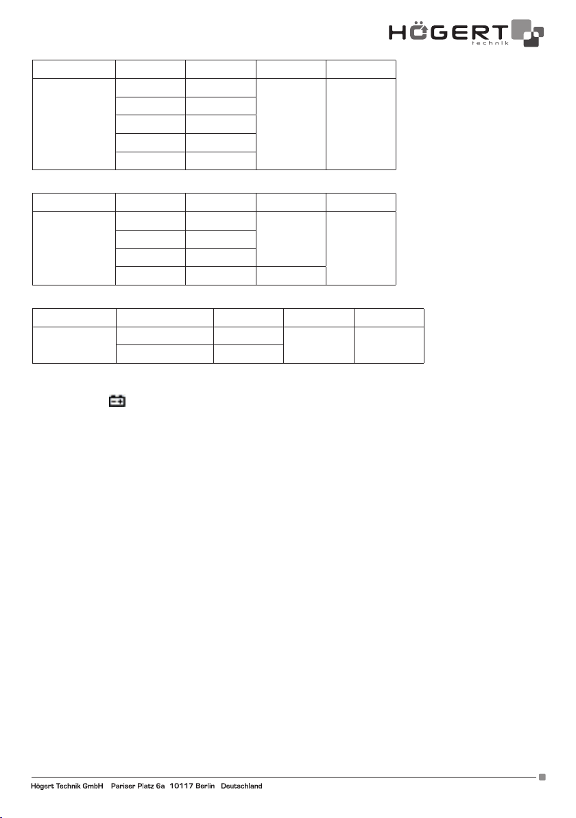
5. Capacité F
Fonction Étendue Résolution Précision Max
40nF 10pF
400nF 100pF
Capacité
4uF 1nF
±(4.0%+5d) 400uF
40uF 10nF
400uF 100nF
6. Fréquence Hz
Fonction Étendue Résolution Précision Max
4kHz 1Hz
Fréquence
40kH 10Hz
400kH 100Hz
±(1.5%+8d)
4MHz
4MHz 1kHz ±(1.5%+40d)
7. Température
Fonction Étendue Résolution Précision Max
Température
-40°C~400°C 1°C
-400°C ~1000°C 1°C
±(1%+8d)
±(1.5%+15d)
1000°C
6. MAINTENANCE
6-1. Remplacement de piles
Dès que le symbole
apparait sur l’affichage LCD pendant l’utilisation du mesureur, il faut remplacer la pile pour prévenir une
lecture incorrecte des mesures .
1. Déconnectez les câbles de test . Coupez le courant.
2. Utilisez un tournevis pour ouvrir le couvercle de pile à l’arrière, puis retirez la pile .
3. Insérez la pile 9V 6F22 et fixez le couvercle .
6.2. Remplacement du fusible
1. D’abord, retirez les fils de test et éteignez le mesureur .
2. Utilisez un tournevis pour ouvrir le couvercle arrière, puis retirez le fusible endommagé .
3. Insérez un fusible similaire, fermez le couvercle arrière et fixez-le avec la vis .
6.3. Maintenance
Si nécessaire, utilisez un chiffon doux pour essuyer la surface du compteur. Ne pas utiliser de solvants organiques ou de matériaux
abrasifs qui pourraient corroder ou dissoudre le boîtier.
Adres producenta/ Adresse des Herstellers/ Manufacturer’s Address/ Адрес производителя
GTV Poland Sp. z o.o. Sp. k., ul. Przejazdowa 21, 05-800 Pruszków www.hoegert.com
25
 Loading...