

Page 1
user manual
um SG100-IM/Rev.C0/08-12
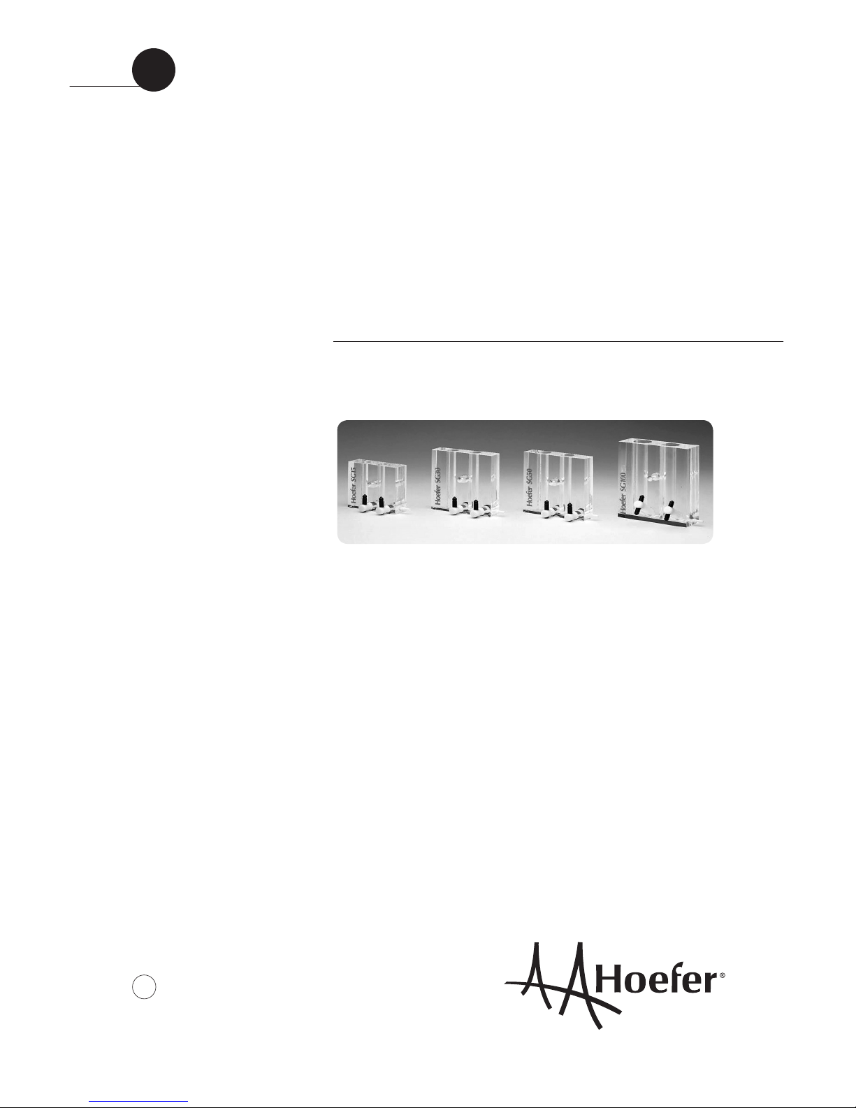
Hoefer SG15, SG30,
SG50 and SG100
Gradient makers
Page 2
•
pi
Page finder
1. Introduction: Hoefer SG15, SG30, SG50,
and SG100 gradient makers ............................... 1
2. Generating linear gradients .................................2
Pouring gradients from the top ..........................4
Pouring gradients from the bottom ......................5
3. Care and maintenance ....................................... 6
4. Ordering information ..........................................6
Page 3
•
p1
1. Introduction: Hoefer SG15,
SG30, SG50, and SG100
gradient makers
The Hoefer® SG gradient makers are designed
for producing linear gradients of aqueous solutions ranging in volume from 15–100 ml. The
gradient makers are machined from solid blocks
of acrylic plastic. They are suitable for casting
acrylamide pore gradient gels, casting immobilized pH gradient gels, pouring density gradients
for centrifugal sedimentation separations and
delivering salt gradients for low pressure chromatography systems.
The gradient makers have a white Luer outlet
fitting that can take either tubing with female
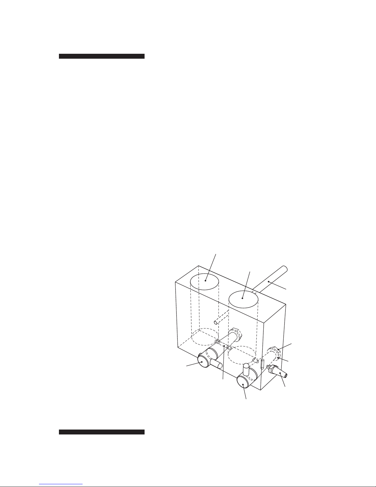
Fig 1. Hoefer SG gradient maker.
Included but not shown:
Adaptor barbed fitting (1)
22-gauge needle (1)
reservoir (black)
chamber
mixing (front)
chamber
support
rod
stopcock
nut
stopcock
washer
white Luer outlet
connector (4 mm
id tubing)
delivery
stock
connector
channel
connector
stopcock
Page 4

•
p2
Luer connectors or tubing of 4 mm inside
diameter (ID). Also included with the gradient
maker is a support rod (that can be screwed into
the body of the gradient maker, allowing it to
be clamped onto a vertical stand), an adapter
barbed fitting (to convert the end of a 2 mm
ID tubing into a female Luer connector) and
a 22-gauge needle (that can be attached to the
white Luer outlet fitting so that it can accept
22-gauge tubing).
2. Generating linear gradients
To generate a linear gradient between two
concentrations, equal volumes of solutions of the
two concentrations are measured into the two
chambers of the gradient maker. As solution is
delivered out of the mixing chamber, an equal
volume flows in from the reservoir chamber
where it is rapidly diluted and mixed to uniformity by a magnetic stir bar. The initial concentration delivered will be that of the solution in
the mixing chamber, the final concentration will
be that of the reservoir chamber. For the most
consistent delivery of gradients, a peristaltic
pump is recommended.
Table 1. Operating ranges for linear gradients
model max total vol min vol/chamber max stir bar length
(ml) (ml) (mm)
SG15 15 3 12
SG30 30 5 15
SG50 50 8 15
SG100 100 16 20
Page 5

•
p3
1
Make sure all parts are clean and liquid flows freely
through all channels, stopcocks and tubing.
2
Add a magnetic stir bar of the appropriate dimensions
to the mixing chamber (Table 1) and place the unit
on a magnetic stirrer. If volumes will be less than half
the capacity of the unit, an identical stir bar should
be placed in the reservoir chamber as well to balance
the displacement and prevent backflow into the reservoir when the chambers are first connected. Connect
tubing to the outlet connector and pump, and adjust
pump speed, if used. Position or connect the tubing
to the receiving vessel (gel casting unit, centrifuge
tube, etc.).
3
Close both stopcocks (handles up) and add the
required volume of the final solution to the reservoir
(back) chamber.
4
Carefully open the connector stopcock and allow just
enough solution to flow through the connector channel
to fill it to the edge of the mixing chamber, then close
the stopcock. Be sure no large bubbles remain to
obstruct flow through the channel.
5
Add the required volume of the starting solution to the
mixing chamber and start the magnetic stirrer.
6
Open the delivery stopcock.
7
Simultaneously open the connector stopcock and start
the pump.
Note: If there is a substantial
difference in densities between
the two solutions, there will be
a sudden flow from the denser
chamber to the lighter chamber
to bring the two into hydrostatic balance. This will result
in the gradient not being fully
linear. To avoid this, add equal
weights, rather than volumes,
of the solutions to the appropriate chambers.
Page 6

•
p4
8
If it is important that no bubbles disturb the
gradient, watch the delivery carefully and as soon
as the last of the solution has entered the pump
head, stop the pump and remove the tubing from
the receiving container.
9
Flush and rinse all parts thoroughly with distilled
water after use.
Pouring gradients from the top
Filling a container with a gradient (e.g. casting
acrylamide pore gradient gels) can be done either
dense solution first (“from the top”), or light
solution first (“from the bottom”).
To fill from the top:
1
Proceed as described on page 3, putting light (final
or top) solution in the reservoir chamber (step 3) and
dense solution in the mixing chamber (step 5).
2
Place the delivery outlet against the upper edge of
the receiving container. Adjust the pump rate so that
the solution flows evenly down the side in a smooth,
continuous stream. The delivery speed should be slow
enough that the newly arriving solution does not mix
with the underlying solution. Alternatively, using a
rigid cannula at the end of the delivery tubing, hold
the tip of the cannula just above the surface of the
solution, raising it smoothly as the container fills.
Page 7

•
p5
Pouring gradients from the bottom
This technique is commonly used in filling
multiple gel casting chambers.
1
Proceed as described on page 3, putting dense (final
or bottom) solution in the reservoir chamber (step 3)
and light solution in the mixing chamber (step 5).
2
Connect the delivery tubing to the bottom inlet of a
gel casting unit or to a cannula long enough to reach
the bottom of the receiving container. Adjust the
pump rate so that the solution is not forced up in a
“fountain” that mixes with the overlying solution.
3
If all of the gradient solution must be delivered to the
container, a displacement solution may be used. Just
as the last of the gradient mix is pumped out of the
mixing chamber, and before any air enters the tubing,
add an appropriate volume of a denser displacement
solution to the mixing chamber and pump it through
until all of the gradient mix has been delivered. It is
convenient to include a dye in the displacement solution to visually track the boundary between the gradient mix and the displacement solution.
Page 8

•
p6
3. Care and maintenance
The gradient maker should be cleaned thoroughly
with distilled water after use to prevent polymerization or crystallization of solutions in the
chambers and stopcocks. Do not use abrasives,
acetone, pure alcohols or organic solvents to
clean this unit.
4. Ordering information
product qty. code no.
SG15 gradient maker, 1 SG15
15 ml total volume
SG30 gradient maker, 1 SG30
30 ml total volume
SG50 gradient maker, 1 SG50
50 ml total volume
SG100 gradient maker, 1 SG100
100 ml total volume
White Luer outlet fitting, (4 mm) 1 SG100-6
SG15, SG30, SG50, SG100
Stopcock, standard size, 1 SG100-1
for SG15, SG30, SG50
Long stopcock, for SG100, 1 SG100-9
connector stopcock
Short stopcock, for SG100, 1 SG100-10
delivery stopcock
SG500 gradient maker, 1 SG500
500 ml total volume
Page 9

•
p7
Hoefer, Inc.
84 October Hill Road
Holliston, MA 01746
Toll Free: 1-800-227-4750
Phone: 1-508-893-8999
Fax: 1-508-893-0176
E-mail: support@hoeferinc.com
Web: www.hoeferinc.com
Hoefer is a registered trademark
of Hoefer, Inc.
© 2012 Hoefer, Inc. —
All rights reserved.
Printed in the USA.
 Loading...