

Page 1
user manual
SE 400/SE 410
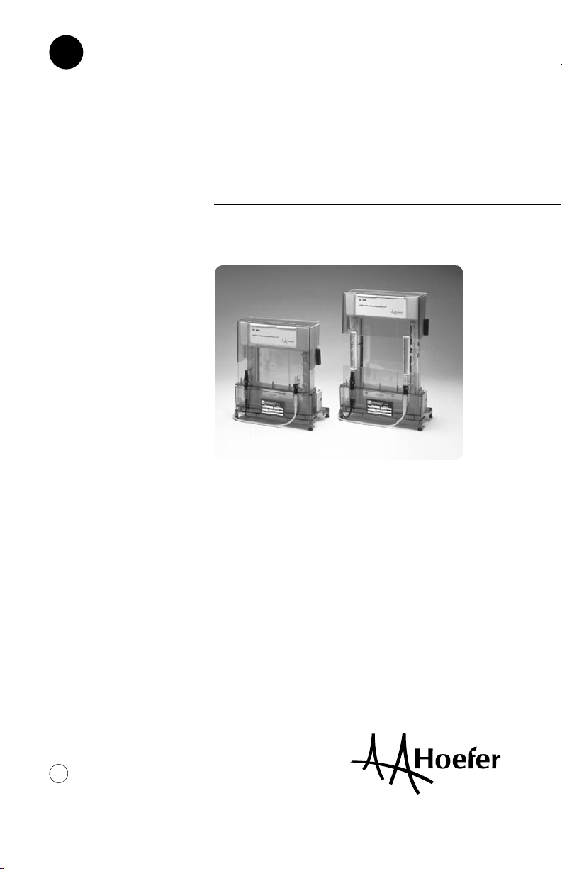
Hoefer SE 400/SE 410
the Sturdier vertical slab gel electrophoresis units
um SE400-IM/Rev. A0/06-04
Page 2

Page 3

Page finder
1. Gel electrophoresis unit function and description
Unpacking and disassembly ............................................ 2
Annotated inventory ........................................................ 4
Specifications ................................................................6
2. Operating instructions
2.1. Gel casting preparation
2.1.1. options—precast and self cast gels ............ 7
2.1.2. preliminary casting steps ........................... 8
2.2. Acrylamide gel preparation
2.2.1. resolving gel ........................................... 11
2.2.2. stacking gel ............................................12
2.2.3. gradient gel ............................................ 13
2.3. Sample preparation ...........................................15
2.4. Final assembly ................................................. 16
2.5. Resolving the sample ........................................20
2.6. After electrophoresis .........................................23
3. Care and maintenance ........................................... 24
4. Troubleshooting ...................................................... 25
Appendices
A. Laemmli System Gels ............................................... 29
B. Bibliography ............................................................ 37
Ordering information ................................................... 39
pi
•
Page 4

English
Safety warnings and precautions
• Only use a power supply that is CE marked or
safety certified by a nationally recognized testing
laboratory.
• Turn all power supply controls off before plugging
in or removing the power leads, and only connect or
disconnect leads when the safety lid is in place.
• Do not operate at temperatures above 45 °C.
All plastic parts are rated for 45 °C continuous
duty. Overheating will cause irreparable damage to
the unit!
• If this equipment is used in a manner not specified
by the manufacturer, the protection provided by the
equipment may be impaired.
• Only accessories and parts approved or supplied by
Hoefer, Inc. may be used for operating, maintaining,
and servicing this product.
Français
pii
•
• Utiliser seulement un générateur marqué CE ou
dont la sûreté a été certifiée par un laboratoire de
test nationalement reconnu.
• Eteindre le générateur avant de brancher ou de
débrancher les prises. Le couvercle de sécurité doit
être en place avant de brancher ou de débrancher
les prises au générateur.
• Ne pas utiliser à une température au dessus de
45 °C. Toutes les pièces en plastique sont prévues
pour résister à une température constante de 45 °C.
Toute surchauffe causera des dommages irréparables à l’unité.
• Si cet appareil est utilisé de manière incorrecte ou
non approuvée par le constructeur, la protection
fournie par l’appareil peut etre altérée.
• Seuls les accessoires et pièces détachées approuvés
ou fournis par Hoefer, Inc. sont recommandés pour
l’utilisation, l’entretien et la réparation de
ce produit.
Page 5

1. Unit function and description
The Hoefer™ SE 400 and SE 410 Sturdier™ Vertical Slab Gel Electrophoresis Units are intended
for electrophoretic separation of proteins and
nucleic acids under both denaturing and native
conditions. Up to 28 samples can be compared
on a single slab gel. One gel (or two gels if using
the divider plate, ordered separately) is cast in
the casting stand side of the unit. The size of
the gel is 14 × 15 cm if using the SE 400, and
14 × 23 cm if using the SE 410. After casting,
the sandwich is transferred into the lower buffer
chamber for electrophoresis.
The basic unit includes one set of glass plates
(18 × 16 cm for the SE 400, and 18 × 24 cm for
the SE 410), two clamp assemblies (SE 400: two
16 cm clamps; SE 410: two 16 cm clamps and
two 8 cm clamps), and two cams. The complete
unit includes one 15-well comb and two spacers,
1.5 mm thick, in addition to the basic unit.
p1
•
Page 6

Unpacking and disassembly
Unwrap all packages carefully and compare
contents with the packing list, making sure all
items arrived. If any part is missing, contact
your local sales office. Inspect all components
for damage that may have occurred while the
unit was in transit. If any part appears damaged,
contact the carrier immediately. Be sure to keep
all packing material for damage claims or to use
should it become necessary to return the unit.
This unit is partially assembled to protect
components during shipping. To disassemble:
1
Position the unit so that the electrical connectors
face you.
2
Note the holes at each side on the upper buffer
chamber. Rest your thumbs in these holes and use
your index fingers to lift the sides of the safety lid
gently until the electrode connectors unplug. First lift
the lid straight up so that the upper electrode shield
clears the upper chamber and then lift the lid out
(toward you) to remove it completely.
3
Lift out the upper buffer chamber and then the glass
plate assembly.
4
Remove the clamps by loosening the thumb screws.
p2
•
Page 7
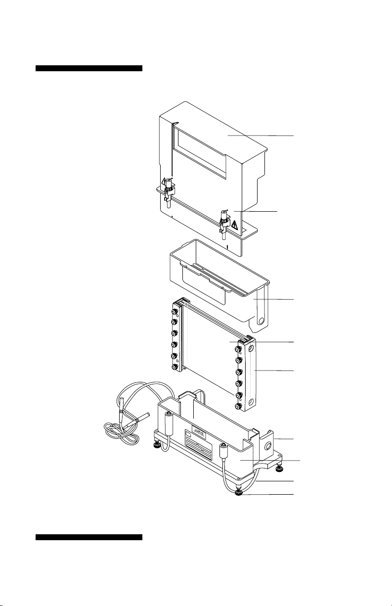
Fig 1. SE 400 series
main components.
Included but not shown:
Cams
GelSeal grease, 1/4 oz.
Spacer-Mate
Wonder Wedge
Level
Required but not included:
Approved power supply
safety lid
color-coded connectors (2)
upper buffer chamber
glass plates (2)
clamps
casting cradle
lower buffer chamber
color-coded leads (2)
leveling feet (4)
•
p3
Page 8

Annotated inventory
Buffer chambers. Both buffer chambers are
chemically resistant to common electrophoretic
buffers but not to organic solvents or strong
acids and alkalis.
Safety lid. The lid contains both electrodes and
both electrode connectors. The electrode connectors plug into the lead connectors on the lower
buffer chamber. The color-coded leads plug into
color-coded jacks on the power supply.
Glass plates. Two 18-cm wide glass plates are
included. Plates for the SE 400 are 16 cm long,
and plates for the SE 410 are 24 cm long.
(A notched divider plate, ordered separately,
can be used to run two gels at the same time.)
Clamps. Two 16-cm clamps are required to
secure the 16 cm long sandwich. These and an
additional pair of 8-cm clamps are required to
secure a 24-cm long sandwich.
Casting stand. The caster can be leveled with
the adjustable leveling feet on the bottom of the
unit. A laminated gasket seals the bottom of
the glass plate assembly when it is locked into
the stand.
Cams. Cams are used twice; first to secure the
assembled sandwich in the casting stand and
again to lock the sandwich and the upper buffer
chamber together.
Rubber gaskets. There are two gaskets. The
laminated gasket fits into the bottom of the cast-
p4
•
Page 9

ing stand and provides the seal for the bottom
of the gel sandwich. The slotted gasket fits
under the upper chamber and provides the seal
between the sandwich and the upper chamber.
Two ridges help position this gasket.
Spacer-Mate assembly template. Aligns spacers
for sandwich assembly.
Wonder Wedge Plate Separator Tool. Use to
disassemble gel sandwiches and to gauge spacer
and comb thickness.
Spacers. (May be ordered separately.) Spacers
determine the thickness of the gel. They are 2 cm
wide and are available in three thicknesses: 0.75,
1.0, and 1.5 mm.
Combs. (May be ordered separately.) Teflon™
combs that form 1 to 28 wells are available in
three thicknesses: 0.75, 1.0, and 1.5 mm. Blank
combs form a single large well, and preparative
combs include 1 or 2 reference wells in addition
to the preparative well.
All blanks, preparative combs, and combs with
fewer than 28 wells form wells that are 25 mm
deep. The 28-well comb forms wells that are
only 15 mm deep so that wells do not collapse
when the comb is removed. The sample volume
held by each well depends on the gel thickness,
well depth and the number of wells per comb.
Table 2 on page 15 lists volume per 1 mm depth
for wells created by each comb size. See the
ordering information for additional comb
specifications.
p5
•
Page 10

This declaration of conformity
is only valid for the instrument
when it is:
• used in laboratory locations,
• used as delivered from
Hoefer, Inc. except for
alterations described in
the User Manual, and
• connected to other CE
labeled instruments or
products recommended or
approved by Hoefer, Inc
Specifications
Glass plate size SE 400: 18 × 16 cm
SE 410: 18 × 24 cm
Approximate gel size SE 400: 14 × 15 cm
SE 410: 14 × 23 cm
Max. wattage 20 W
Max. voltage 500 V @ 40 mA
Max. amperage 30 mA/gel
(60 mA total @ 325 V)
Max. temperature 45 °C
Environmental Indoor use: 4–40 °C
operating conditions Humidity up to 80%
Altitude up to 2000 m
Installation category: II
Pollution degree: II
Dimensions (w × h × d) SE 400: 24 × 28 × 15 cm
(9.5 × 11 × 6 in.)
SE 410: 24 × 36 × 15 cm
(9.5 × 14.2 × 6 in.)
Product certifications EN61010–1, UL3101–1,
CSA, C22.2 1010.1, CE
p6
•
Page 11

2. Operating instructions
Procedures for casting gels and electrophoretic
separation follow. Included are instructions for
both single percentage (homogeneous) and
gradient polyacrylamide gels. Appendix A lists
recipes and Appendix B gives a bibliography.
2.1. Gel casting preparation
2.1.1. options—precast gels and self-cast gels
The SE 400 unit accepts standard precast gels
purchased from commercial suppliers as well
as self-cast gels, which can be prepared using
the built-in casting stand. (To cast multiple
14 × 16 cm gels, the Multiple Gel Caster Kit,
which holds up to 10 sandwiches, and the Gel
Caster Kit, which holds up to four sandwiches,
can be ordered separately.) Gels for the SE 410
must be self-cast.
Glass plates, spacers, and clamp sets are sized
so that the assembled sandwich can be easily
aligned to create the required seal. When assembling sandwiches, take extra care to align all
components for best results.
p7
•
Page 12
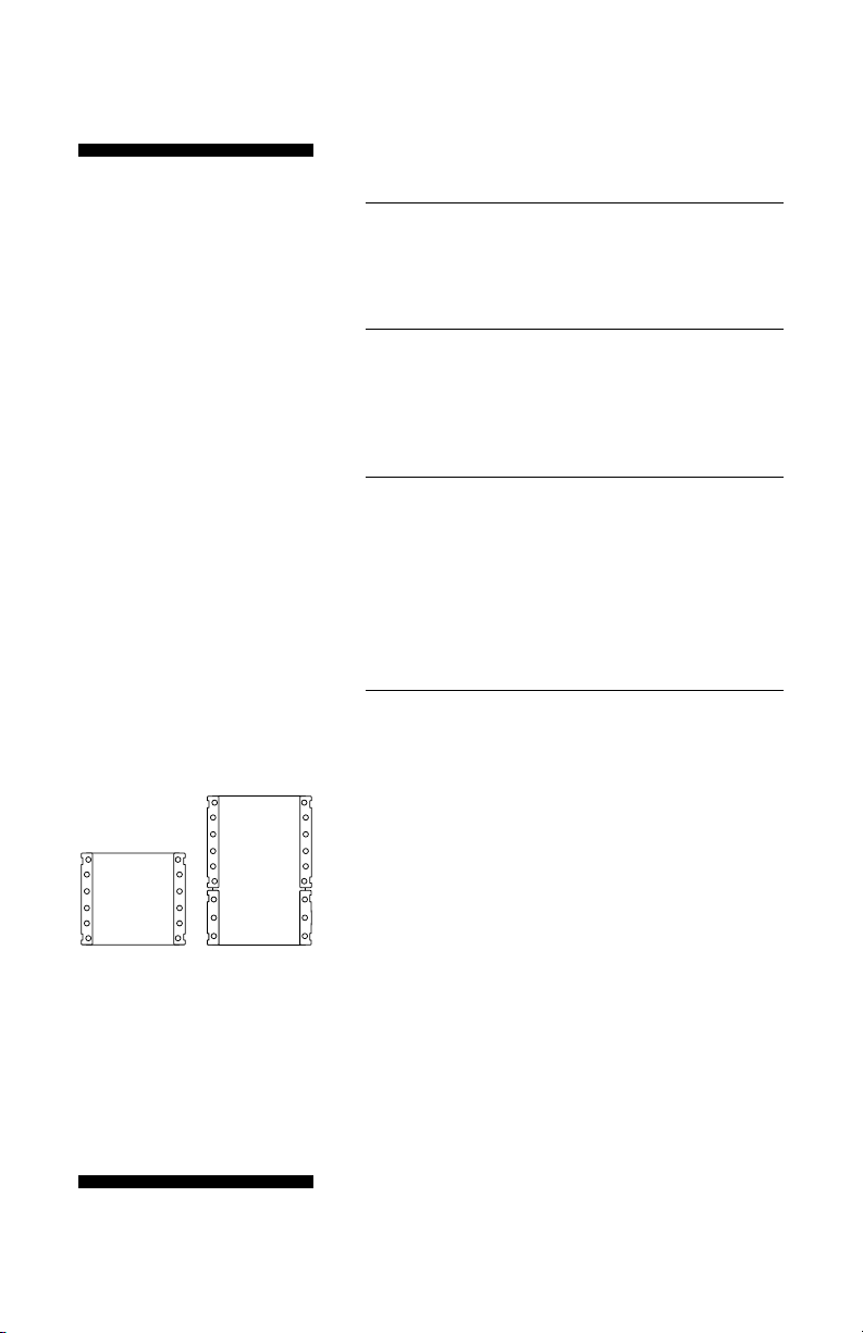
16 cm
(SE 400)
Fig 2. A 24-cm sandwich requires
two 16-cm and two 8-cm clamps.
24 cm
(SE 410)
2.1.2. preliminary casting steps
1
Prepare the caster
Place the spirit level into the lower buffer chamber
and adjust the leveling feet.
2
Prepare the clamps
Loosen all clamp screws and make space for the
sandwich by sliding the pressure plates toward
the screws.
3
Construct each gel sandwich
For each sandwich, choose two perfectly clean
unchipped glass plates and two spacers. Lay one
plate on a flat surface, lay the Spacer-Mate assembly
template onto the plate (wide side at the top), place
a spacer along each edge, and lay the second glass
plate on top.
4
Secure the sandwich with clamps
Slide one clamp at a time along the sandwich sides.
Finger tighten one screw on each clamp, set the
sandwich upright on a flat surface, and loosen the
screw to align the stack. Take great care in aligning to
ensure a seal. Finger tighten all screws. Remove the
Spacer-Mate.
24-cm sandwich (SE 410)
A 24-cm sandwich requires two clamp assemblies on
each side. Align each end separately. That is, align
one end, finger-tighten the screws, turn the sandwich
180° and align the other end. In each case allow the
clamp to slide down and align perfectly with the top
(or bottom) edge of the glass plates.
For 24 cm long plates, position the 8 cm clamp at
the bottom (see Fig 2).
p8
•
Page 13
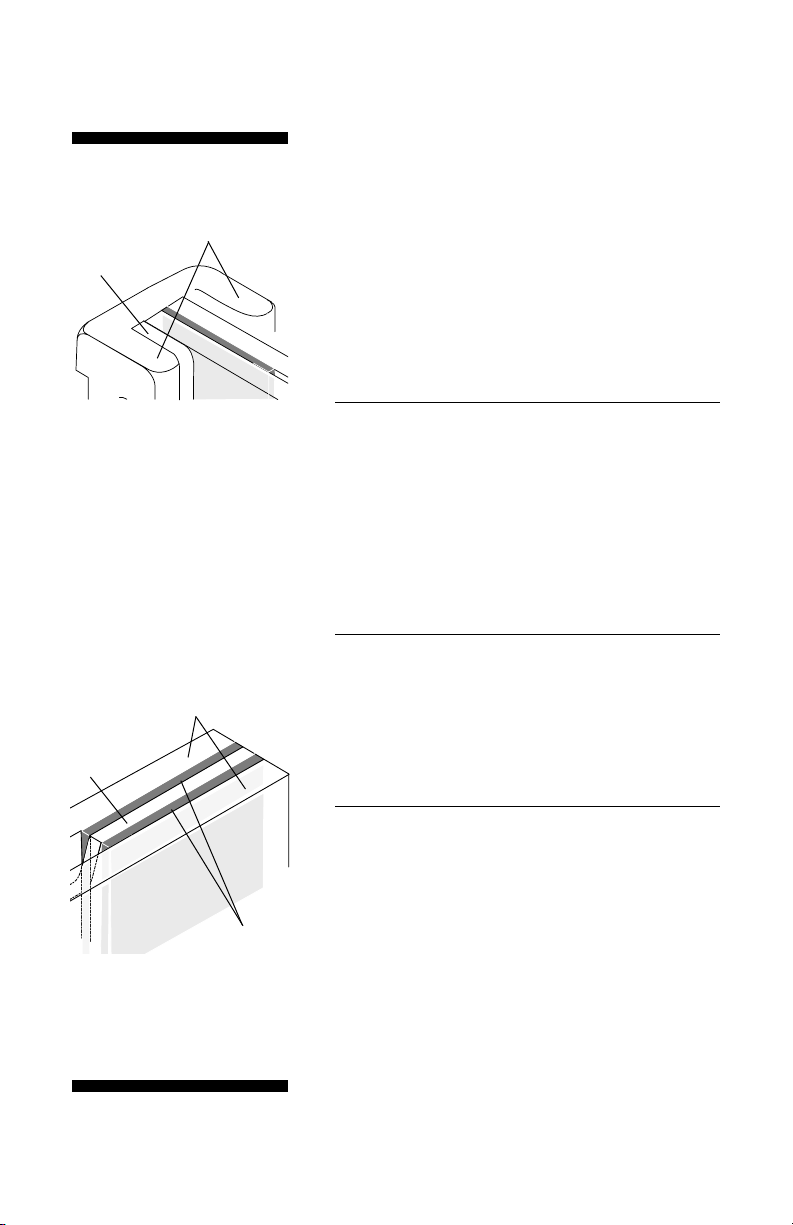
both top and bottom
sandwich edges must
be flush with the
clamp guide ridges.
pressure bar
Fig 3. Sandwich assembly:
Inspect glass plates for nicks.
Use only unchipped plates to
prevent leaking.
Tip: Remove the laminated
gasket from the cradle and use
the casting cradle to hold the
sandwich for alignment.
glass plates
(at the outer sides
of the sandwich)
notched
divider
plate
spacers
Fig 4. 2-gel sandwich assembly:
2-gel sandwiches are limited to
thinner gels; no spacers thicker
than 1.5 mm can be used.
2-gel sandwich
A 16- or 24-cm long notched divider plate (ordered
separately) doubles the number of gels that can be
cast and run (see Fig 4).
Assemble in the same manner as a single gel sandwich, except before placing the top glass plate, lay
the divider plate atop the first set of spacers and a
second set of spacers atop the divider plate. Place the
notch so that it will be at the top of the gels. As with
a regular sandwich, it is essential that the spacers and
plates align perfectly in order to create a seal.
5�
Inspect the bottom of the sandwich to make sure that
edges are aligned flush in order to ensure a complete
seal. Adjust if necessary (see Fig 3).
Optional: Apply a light film of GelSeal only on the
bottom outside corners if your sandwiches tend to
leak. Do not use silicone grease or petroleum jelly
to seal the sandwich because these substances are
difficult to remove and ultimately may cause artifacts
in the gel.
6��
Place the laminated gasket into the casting cradle
with the foam side down. Place the glass plate
assembly in the casting cradle, screw side facing
out (see Fig 5).
24-cm plates: Place the sandwich so that the short
clamps are at the bottom.
7�
Insert a cam into the hole on each side of the casting
tray with the ridge (short end) pointing up. Seal the
gel sandwich by turning both cams as far as needed,
usually 90° to 150°, up to 180°. The cam action
presses the plates into the gasket to seal the bottom
of the sandwich. The seal is complete once the glass
edge appears darker and nearly transparent against
the gasket. Do not tighten the cam past this point.
p9
•
Page 14
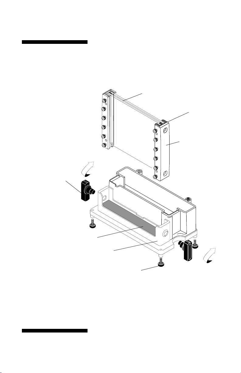
Fig 5. Caster components
and assembly.
1. Lower the assembled sandwich
into the casting cradle.
2. Insert cams into the cam holes,
ridge end up.
3. Turn cam up to 180° until
the glass plates seal against
the gasket.
cams (2)
insert the cam(s) in
the cam holes and
turn toward the center
to lock the glass plate
assembly.
glass plates (2)
spacers
clamps
(the number required
depends on the
plate length.)
•
gasket (foam side down)
casting cradle
leveling feet (4)
Note: It is easier to keep the caster balanced if you
turn both cams toward the center of the caster.
p10
Page 15

2.2. Acrylamide gel preparation
Table 1. Approximate monomer solution volume
required for a single gel
Gel thickness (mm)
Model 0.75 1.00 1.5
SE 400 15 ml 23 ml 30 ml
SE 410 23 ml 34 ml 45 ml
2.2.1. resolving gel
1��
Prepare the monomer solution and pour the gel.
Prepare the required amount of monomer solution,
deaerate, and add the initiator and catalyst just prior
to pouring the gel.
Note: Appendix A lists recipes
for the Laemmli gel system.
2��
Pipet the solution into one corner of the sandwich,
taking care not to introduce any air bubbles. See
below for the appropriate solution level:
No stacking gel
(Continuous system.) Fill solution to just below the
top of the upper plate edge. If bubbles are trapped,
remove with a pipet or syringe. Introduce a comb (at
a slight angle) into each sandwich, taking care not to
trap air bubbles under the teeth.
2-gel sandwich
Pipet the solution into both sandwiches, filling each
to the same level below the notched edge.
Stacking gel
Fill solution to 3–4 cm below the top of the glass
plate. This height allows 1 cm of stacking gel below
the wells. Pour the gel and apply an overlay (see step
3). After the gel is set, prepare the stacking gel as
described in the next section.
2-D electrophoresis
(Discontinuous system) For the second dimension
resolving gel, fill solution to ~1.0 cm below the top of
the glass plate (leave extra space for a stacking gel, if
required). One centimeter allows enough space for the
first dimension IPG strip or tube gel and an agarose
seal. (While transferring, take care to avoid trapping
air between the tube gel and slab gel; seal the tube
gel into place with agarose in electrophoresis buffer.)
•
p11
Page 16

3
If combs are in place, skip to step 4.
If no combs are in place, overlay the resolving gel
with a thin layer of water-saturated n-butanol, water,
or diluted gel buffer to prevent exposure of the top
surface of the gel solution to atmospheric oxygen.
Slowly deliver the overlay solution from a glass
syringe fitted with a 22-gauge needle. Apply the
solution near the spacer and allow it to flow across
the surface unaided.
4
Allow the gel to polymerize for a minimum of
one hour.
2.2.2. stacking gel
Pour the stacking gel before removing the sandwich
from the gel caster. Stacking gel resolution is optimal
when prepared just before electrophoresis.
1
Remove the overlay by rinsing the top of the gel
several times with distilled water. Invert the caster
to drain. To ensure a seamless contact between the
resolving and stacking gels, remove residual liquid by
blotting one corner with a lint-free tissue.
2
Calculate the stacking gel monomer solution volume.
•
3
Prepare the stacking gel monomer solution, deaerate
it, and add catalyst and initiator. Pour the stacking
gel onto the resolving gel with a disposable or Pasteur
pipet to a level about 2 mm from the top of the
glass plate.
4
Introduce a comb (at a slight angle) into the sandwich, taking care not to trap air under the teeth. Allow
a minimum of one hour for the gel to polymerize.
p12
Page 17

Fig 6. Pouring a gradient gel
Note: With Coomassie™ Blue,
it is possible to detect 1 µg in
a single band; with the more
sensitive silver stains, it is
possible to detect as little as
10 ng.
2.2.3. gradient gels
Linear gradient gels can be poured in the gel caster.
For easy gradient mixing, we recommend using one of
the Hoefer SG series gradient makers. Gradient gels
are poured from the top of the caster with a cannula
if using the provided gel caster or from the bottom if
using a Hoefer multiple gel caster (see instructions
accompanying the caster). Once the gradient gel
polymerizes, a stacking gel is poured.
1
Assemble the glass plate assembly into the caster as
described in section 2.1.2.
2
Set up the monomer solution flow path. Run a length
of clear vinyl tubing through a peristaltic pump.
Attach one end of the tubing to the gradient maker
outlet port and the other end to a 20 cm cannula.
(The outside diameter of the cannula must be less
than the spacer thickness.) Place the cannula so
that it rests at the bottom of the sandwich, midway
between the spacers.
3
Prepare the monomer solution. Calculate the total
volume needed. Prepare one half of this volume of
higher and the other half of lower % acrylamide solution. (Optional: Add 15% sucrose or 25% glycerol
[final concentration] to the higher % solution to
improve layering.)
4
Pour the “light” solution into the reservoir chamber
(the chamber furthest from the inlet). Open the
stopcock long enough to displace air between the
chambers and then close. Pour the “heavy” solution
into the mixing chamber and place a stirring bar into
this chamber. Place the gradient maker on a magnetic
stirrer and begin stirring at a rate that does not
introduce bubbles in the solution.
•
p13
Page 18

5
Mix the gradient. While the solution is stirring, begin
pumping (5–10 ml/min) from the mixing chamber and
immediately open the stopcock to the reservoir chamber. Raise the cannula as liquid enters the sandwich,
keeping the tip at the gel surface.
6
Overlay each gel with a thin layer of water-saturated
n-butanol, water, or diluted gel buffer to prevent gel
exposure to oxygen. Slowly deliver the overlay solution
from a glass syringe fitted with a 22-gauge needle.
Apply the solution near the spacer and allow it to flow
across the surface unaided.
7
Allow the gel(s) to polymerize for a minimum of one
hour. After polymerization, pour off the overlay and
rinse the gel surface several times with distilled water.
8
Prepare the stacking gel monomer solution, pour the
stacking gel and introduce a comb (at a slight angle)
into the sandwich, taking care not to trap air under
the teeth. Allow a minimum of one hour for the gel
to polymerize.
•
p14
Page 19

2.3. Sample preparation
The amount of sample loaded depends on the
thickness of the gel, the sensitivity of the detection method used, and the amount of sample
expected in each band. In a continuous buffer
system, the protein sample should be relatively
concentrated because no stacking gel is used.
In a discontinuous buffer system, the zone into
which each molecular species migrates is sharpened by the stacking gel, so the sample need not
be as concentrated.
Table 2. Well volume (µl) per
1 mm depth for each comb size
Comb thickness
(mm)
No. of wells 0.75 1.0 1.5
10 6.2 8.3 12.4
12 5.8 — 11.5
15 4.3 5.7 8.6
20 3.1 4.1 6.2
28 2.1 2.7 4.1
1
Prepare the wells. Remove the comb by gently
rocking it side to side and then lifting it straight
up to avoid damaging the well walls. Carefully rinse
each well with electrophoresis buffer to remove
unpolymerized acrylamide and then drain by inverting
the gel sandwich (or caster). Fill each well with
electrophoresis buffer.
2
Prepare the sample. Increase liquid sample density
with 10% glycerol or sucrose. Add a tracking dye such
as phenol red, bromophenol blue, or pyronin Y.
For SDS protein gels, use 2X treatment buffer to
denature both liquid and dry samples in a test tube:
To liquid protein samples, add an equal volume of
2X treatment buffer.
To dry protein samples, add equal volumes of 2X
treatment buffer and deionized water to achieve the
desired concentration.
Heat the tube in boiling water for 90 seconds, then
allow to cool to room temperature. Treated samples
can be stored at -40 to -80 °C for future runs.
Heat membrane proteins to 60 °C for 20 minutes.
Store unused sample at 4 °C.
•
p15
Page 20

Note: Before the first use,
disassemble the unit and
wash with a dilute solution
of a laboratory detergent and
rinse thoroughly, first with
water and then distilled water.
Note: To help hold the gasket
against the upper buffer
chamber, dab a small amount
of GelSeal at each end of the
gasket only and then install.
Important! A smooth fit
between the sandwich and
gasket is essential for a
good seal.
2.4. Final assembly
1
Rinse both buffer chambers with water and distilled
water thoroughly before each use.
2
Install the gel sandwich in the lower buffer chamber
Release the sandwich from the caster by removing
both cams. Clean away any gel adhering to the
exterior of the gel sandwich. Install the sandwich
in the lower buffer chamber, clamp screws facing
toward the leads.
3
Carefully fill each sample well with electrophoresis
buffer, then underlay prepared sample into the
wells using a fine-tipped microsyringe or gel loading
pipet tip.
4
Attach the upper buffer chamber to the gel sandwich
Invert the upper chamber and press the slotted gasket
into the grooves for a precise fit.
Proceed with care so that the samples are not
disturbed: Lower the upper chamber onto the gel
sandwich. Install the cams, ridge pointing down, into
the cam holes as shown on page 17. Simultaneously
turn one cam clockwise and the other counterclockwise a full 180° to secure the assembly.
•
p16
Page 21

Fig 7. Upper buffer chamber
assembly: First place the upper
chamber onto the sandwich
assembly, then insert the cams
into the cam holes, ridge (short
end) pointing down. To secure the
assembly, turn the cams a full
180° so that the ridge points up
(not shown).
cam starting
position
final clamping
position
•
p17
Page 22

Note: Do not force the cams.
If encountering unusual resistance, disassemble the unit
and inspect clamp and glass
alignment along the top of the
sandwich. Align and reinstall
the upper chamber.
Note: If the assembly leaks,
take the assembly to a sink
and partially release the cams
to allow buffer to drain.
Remove the upper chamber,
check alignment of all sandwich components, and adjust
if necessary.
5
Pour ~100 ml of electrophoresis buffer into the upper
chamber, directing the buffer stream against the wall
to avoid disturbing the samples. Inspect the installation
for leaks. Fill both chambers (the final volume for each
chamber is ~350 ml).
6
Safety lid installation.
Built-in safety features require that all three guides are
properly placed (see Fig 8).
7
Plug the color-coded leads into the jacks of an
approved power supply (min. 50 mA, 300 V). Plug the
red lead into the red output jack and the black lead
into the black output jack. In most systems, the red
lead, which is connected to the bottom electrode, is
the anode (+), and the black lead, connected to the
top electrode, is the cathode (–).
•
p18
Page 23

2
shield guides
1
3
Fig 8. Safety lid installation.
The safety lid seats effortlessly
if all three features are properly
aligned:
1. The recessed upper electrode
shield slides into the upper
buffer chamber.
2. The lower electrode shield fits
into the lower buffer chamber
and rests in front of the shield
guides.
3. The electrode connectors align
and seat.
If you are unfamiliar with the installation, please
note: The upper electrode is protected by a
recessed shield, which rests in the upper buffer
chamber once the lid is installed. It is easiest to
install the lid by first approaching the upper buffer
chamber from the front, and then sliding the safety
lid down straight down onto the connectors. If
the lid does not fit properly, check the position of
the lower electrode shield, which must clear the
connectors and rest in the lower buffer chamber, in
front of the the shield guides. Once all guides are
in place, press gently to connect the plugs.
•
p19
Page 24

Note: The cross section (and
current requirement) is determined by gel thickness. The
running time is determined by
the length of the plate.
2.5. Resolving the sample
Electrophoresis parameters for discontinuous
polyacrylamide gels
Gels may be run at either constant current or
constant voltage settings. A constant current
setting is traditionally used with a discontinuous
buffer system so that the rate of electrophoretic
migration remains unchanged throughout the
run. Under constant current conditions, the
voltage increases as the run proceeds. A lower
current setting is recommended for higher resolution. The optimal current level must be determined empirically; the main factors that must be
balanced are the gel concentration and migration
speed, and the resulting Joule heating and band
distortion. Table 3 lists starting point guidelines
and adjustments for gel thickness, number of
gels, and migration rate.
Table 3. Laemmli buffer system starting point guidelines
Gel thickness* 1.5 mm
Current per gel† 25 mA constant current
Starting voltage 80–90 V
Gel length (cm) model final voltage (V)
16 SE 400 200–250
24 SE 410 275–325
* Thicker or thinner gels require proportionally more or less current.
For example, a 0.75 mm gel , which is half as thick as a 1.5 mm gel,
requires half as much current, or 12.5 mA.
†
The current must be multiplied by the number of gels. For instance, if
a 1 mm 2-gel sandwich is installed, twice as much current is required
than for a single 1 mm gel at the same voltage.
•
p20
Page 25

Note: Passive cooling, such
as running the unit in a cold
room, may be required to
reduce the effects of
Joule heating.
Important! After initial monitoring, do not leave the unit
unattended for more than
1 hour without checking the
progress of the bands and the
buffer level.
Current
Current acts on the total cross-sectional area of
all the gels, and in terms of a circuit, the gels
are considered to run in parallel. Therefore, any
current setting for one gel must be multiplied by
the number of gels run. For a gel 1.5 mm thick,
we suggest a starting point current setting of
25 mA. (Two 1.5 mm gels = 50 mA.)
Voltage
The starting voltage for a 1.5 mm slab gel
connected to a power supply set to 25 mA is
usually 80–90 V (for the SE 400 model and a
Laemmli discontinuous buffer system). The final
voltage is typically 200–325 V, depending on the
length of the gel. (See Table 3 on page 20.)
Time
A run is complete when the tracking dye reaches
the bottom of the gel. A 16-cm long, 1.5 mm
thick Laemmli SDS gel, run at 25 mA/gel without cooling, usually requires 5 hours. A 24-cm
gel requires about 8 hours.
•
p21
Page 26

Record each run
Keep a record of the current or voltage setting,
number and thickness of gels, buffer system, and
the starting and final current or voltage readings
for each run so that results can be compared.
Inconsistent results for the same system and
settings can indicate potential problems such as
current leaks, incorrect buffer concentrations,
high salt concentrations, or inconsistent
chemical quality.
Check band progress after 5 minutes, and
again after an hour, noting the migration rate
of the tracking dye. The run is complete when
the tracking dye reaches the bottom of the
gel. Watch the buffer level and, if necessary,
replenish it as required to keep the top electrode
submerged. (A small volume of buffer may
leak past a nicked plate or gasket, or buffer
may pass through the gel.)
•
p22
Page 27

Tip: To avoid splashing, add
staining or fixative solution
to the tray after the gel is
transferred.
2.6. After electrophoresis
1
Once the tracking dye reaches the bottom of the gel,
turn off the power supply and disconnect the leads.
Remove the safety lid, using finger leverage—rest
your thumbs on the top of the cams and gently pull
the lid up with your index fingers. Once loose, lift the
lid straight up and then out to clear the ledge on the
upper buffer chamber.
2
Pour out the buffer by inverting the unit over a sink.
Release the upper buffer chamber by removing the
cams. Lift the chamber off and lift the sandwich out
of the lower chamber.
Note: Use only flexible plastic
prying tools to avoid chipping
the glass plates.
3
Unscrew the clamps from the sandwiches and remove.
Gently loosen and then slide away both spacers. Use
the Wonder Wedge plate separator tool to separate
the plates.
4
Carefully lift off one glass plate. Handle the gel with
care to avoid damaging it. Over an empty stain tray,
either invert the plate holding the gel near the bottom
of the tray and lift one corner so that the gel drops
into the tray, or, if the gel is thick enough to handle,
lift it and place into the tray. Add enough fixative or
stain to completely submerge the gel.
5
Clean the unit as described in “Care and
maintenance” on page 24.
•
p23
Page 28

3. Care and maintenance
Cleaning
• Rinse with water immediately after use.
• Do not autoclave or heat any part of the instrument
above 45 °C.
• Do not use organic solvents, abrasives, strong
cleaning solutions, or strong acids or bases to clean
any plastic part.
• Do not soak the gaskets. Clean with a mild detergent
and allow to air dry.
• Handle the safety lid with care to prevent damage to
the electrode connectors.
Clean glass plates and spacers with a dilute
solution of a laboratory cleanser such as
RBS-35™ (Pierce Chemical Co.), then rinse
thoroughly with tap and distilled water. Glass
plates can also be treated with (but not stored
in) acid cleaning solutions.
•
p24
Page 29

4. Troubleshooting
problem/possible cause remedy
Gel sandwich leaks while casting
Dirty or damaged components Plates, spacers, and the gasket must be completely clean.
Replace chipped plates (especially if chipped near
Check the caster gasket for cuts or cracks and replace
Mis-aligned parts Check plate and spacer alignment and realign if necessary.
Over-clamping Turn cam only as far as necessary to create a seal (usually
On each spacer apply a light film of GelSeal compound to the
Sample wells damaged or irregular
Air bubbles Remove air bubbles before inserting combs. Slide comb into
Incomplete or delayed Allow acrylamide gels to set for a minimum of 1 h.
polymerization
Debris in wells Rinse out unpolymerized gel with sample buffer.
Comb removal Remove the comb at a slight angle and very slowly to prevent
damaging the gel.
Agarose gels: Lower the comb no more than 1 cm into the gel.
Incomplete gel polymerization
Chemicals Use only recent stocks of the highest-quality reagents.
If the dry ammonium persulphate does not crackle when
Increase TEMED or APS concentration, or both.
pH Solutions with extreme pH values (especially acidic) may
Oxygen Remove oxygen from the gel environment: Degas the monomer
Temperature Adjust the gel solution temperature to a minimum of 20 °C,
Wash if necessary.
the spacers).
if necessary.
90–150°, but up to 180°).
bottom outside corner only. Do not use silicone grease.
solution at an angle. If comb must be removed, add more
monomer solution before reinserting the comb.
added to water, replace with fresh stock.
not polymerize.
solution 5–10 min before pouring and then overlay the gel
surface with water-saturated n-butanol.
especially for low %T gels.
•
p25
Page 30

problem/possible cause remedy
Upper buffer chamber leaks
Mis-aligned parts Check that the glass plates, spacers, and clamps are aligned
Check that both gaskets are centered and that the positioning
Dirty or Check that the gasket is not damaged or pinched. Replace if
damaged components necessary. Check that the upper buffer chamber is not warped
Dye front curves up (smiles) at edges
Excessive heat Prechill the buffer.
Decrease the current or voltage setting.
Run the gel in the cold room.
Protein streaks vertically
Particulates in sample Centrifuge or filter sample before loading to remove particulates.
Overloading Load less sample.
Degradation Add protease inhibitor such as PMSF.
Unusually slow (or fast) run
Current leakage around gel Check for leaks; all plates and spacers must be aligned
Sample or reagent preparation If the required pH of a solution is overshot, do not
Check recipes, gel concentrations, and buffer dilution.
Decrease the salt concentration of samples.
Reagent quality Dispose of older acrylamide solutions and use only stock of
Use only freshly deionized urea.
Voltage or current settings To increase or decrease the migration rate, adjust the voltage
Bands are skewed or distorted
Incomplete gel preparation Degas the stacking-gel solution and avoid trapping air bubbles
and polymerization under the comb teeth.
Irregular interface between Overlay the running gel with water-saturated butanol before
stacking and running gels polymerization begins, to avoid forming an uneven gel surface.
Sample preparation Dialyze or desalt the sample.
and fit snugly into the upper chamber gasket.
ridges fit inside the grooves.
from prior exposure to excessive heat.
and free of grease and cracks.
back-titrate. Discard and prepare fresh buffer.
(For instance, do not use Tris-HCl instead of Tris for Laemmli
tank buffer.)
the highest quality.
or current by 25–50%.
•
p26
Page 31

problem/possible cause remedy
Stained sample collects:
Near the buffer front
Gel concentration Molecules are not sufficiently restricted by the resolving gel
Degradation Proteins may be degraded by endogenous proteases:
Near the top of the gel when the
buffer front has reached the bottom
Gel concentration The gel pore size is too small: decrease the %T of the
Precipitation The protein has precipitated. Heat the sample at a lower
At both top and bottom of the gel
Gel concentration The molecular weight range of the sample requires an
Poor band resolution
Running conditions Begin electrophoresis as soon as the sample is loaded to
Conduct the separation at a lower current or voltage setting to
Reagent quality Use only the highest-quality reagents.
Poor stacking Use only gels that were recently prepared.
Add a stacking gel or increase height of the stacking gel.
Check pH values of the resolving- and stacking-gel solutions.
Incomplete gel polymerization Allow gel to polymerize fully.
Sample preparation Store sample on ice before it is denatured.
Dialyze or desalt the sample.
Heat samples in SDS sample buffer for no more than
Adjust the sample volume or concentration.
Add more mercaptoethanol or dithiothreitol;
Add protease inhibitors such as PMSF if necessary to prevent
Increase glycerol or sucrose to increase sample density.
Store samples to be frozen in aliquots to avoid repeated
pore size: increase the %T.
use protease inhibitors during the isolation step.
resolving (or stacking) gel.
temperature (70 °C or less) for 1–2 min.
acrylamide concentration gradient to resolve the full range
of protein sizes.
prevent low molecular weight species from diffusing.
reduce Joule heating.
Prepare the resolving-gel surface by first rinsing it with
stacking-gel monomer before pouring the stacking gel to
ensure continuity between the gels.
Do not back-titrate buffers.
1–2 min at 100 °C to improve dissociation of subunits.
Store on ice after heating.
check sample treatment.
proteolytic degradation of sample.
freeze-thawing. Store at -40 to -80 °C.
•
p27
Page 32

problem/possible cause remedy
Tracking dye doesn’t sharpen
into a concentrated zone in
the stacking gel
Poor stacking Pour a taller stacking gel. (For best results, allow a stacking-
Reagent quality Dispose of outdated acrylamide solutions and use only the
Sample preparation When preparing samples, avoid using solutions with high salt
gel height of 2.5 times the height of the sample in the well.)
highest grade of acrylamide.
concentrations.
•
p28
Page 33

Appendix A. Laemmli System Gels
Table 4. Laemmli gels — final concentrations
Electrophoresis
Resolving gel Stacking gel buffer
Acrylamide conc. 10% T*, 2.6% C 4% T, 2.6% C
Tris-Cl 0.375 M 0.125 M
Tris-Glycine 0.025 M Tris base
0.192 M glycine
pH 8.8 6.8 ~8.3
SDS 0.1% 0.1% 0.1%
APS† 0.05% w/v 0.05–0.1% w/v
TEMED‡ 0.05% v/v 0.05–0.1% v/v
* To achieve any other desired final concentration, adjust the acrylamide
stock and water volumes. Volumes for different concentrations are
listed in Table 5.
†
Ammonium persulfate.
‡
Tetramethylethylenediamine
The Laemmli system is the most common electrophoresis protocol for SDS-denatured proteins. The leading
ion in this discontinuous buffer system is chloride and
the trailing ion is glycine. Accordingly, the resolving
gel and the stacking gel contain Tris-Cl buffers (of
different concentration and pH), and the electrophoresis buffer contains Tris-glycine. All buffers contain
0.1% SDS.
Polyacrylamide gel composition is indicated by two
different percentages:
Caution! Acrylamide is a
neurotoxin. Always wear gloves
while handling in any form
and wear a mask while weighing the powder. Never mouth
pipette the solution.
%T =
%C =
g(acrylamide + bisacrylamide)
100 ml
g(bisacrylamide)
g(acrylamide + bisacrylamide)
× 100
× 100
The total percent of acrylamide (%T) in the resolving
gel, which can range from 4 to 20%, determines the
pore size. Commonly, the amount of crosslinker used
(%C) is 2.6%. In the following system example, the
resolving gel composition is 10%T, 2.6%C, which
results in a medium pore size. The stacking gel
composition is 4%T, 2.6%C. The %T in the stacking
gel is lower because a larger pore size is required.
p29
•
Page 34

Solutions
Note: Filter solutions 1–4
through a 0.45 µm filter.
Important! Refer to the
material safety data sheet
(MSDS) accompanying each
chemical for detailed handling
and safety information.
1. Acrylamide stock solution
(30.8% T 2.6% C Bis, 200 ml)
Acrylamide (FW 71.08) 30% w/v 60.0 g
Bis* (FW 154.2) 0.8% w/v 1.6 g
Deionized H2O to 200.0 ml
Store at 4 °C away from light.
*N,N’ Methylenebisacrylamide
2. 4X Resolving gel buffer
(1.5 M TrisCl, pH 8.8, 1 liter)
Tris base (FW 121.1) 1.5 M 181.5 g
HCl to pH 8.8
Deionized H2O to 1000 ml
Store up to 3 months at 4 °C in the dark.
3. 4X Stacking gel buffer
(0.5 M TrisCl, pH 6.8, 500 ml)
Tris base (FW 121.1) 0.5 M 30.3 g
HCl to pH 6.8
Deionized H2O to 500 m
Store up to 3 months at 4 °C in the dark.
4. 10% SDS solution
(100 ml)
SDS* (FW 288.4) 0.35 M 10.0 g
Deionized H2O to 100 ml
Store up to 6 months at room temperature.
*Sodium dodecylsulfate
•
5. 10% APS (Initiator)
(1 ml)
APS* (FW 228.2) 0.44 mm 0.1 g
Deionized H2O to 1.0 ml
Fresh APS “crackles” when water is added. If yours does not, replace it
with fresh stock. Prepare just prior to use.
*Ammonium persulfate
p30
Page 35

6. Resolving gel overlay
(0.375 M TrisCl, 0.1% SDS, pH 8.8, 100 ml)
1.5 M Tris-Cl, pH 8.8 (Solution #2) 0.375 M 25.0 ml
10% SDS (Solution #4) 3.5 mm 1.0 ml
Deionized H2O to 100.0 ml
Store up to 3 months at 4 °C in the dark.
—OR—
Water-saturated n-butanol
Shake n-butanol and deionized H2O in a separatory
funnel. Remove the aqueous (lower) phase. Repeat
this procedure several times. Use the upper phase.
—OR—
If an overlay interferes with the preferred protocol,
isolate the gel from atmospheric oxygen by placing a
preparative comb or resolving gel former on the gel.
7. 2X Sample treatment buffer
(0.125 M TrisCl, 4% SDS, 20% glycerol,
0.2 mM DTT*, pH 6.8, 10 ml)
0.5 M Tris Cl, pH 6.8 (Solution #3) 0.125 M 2.5 ml
10% SDS, 0.35 M (Solution #4) 0.14 M 4.0 ml
Glycerol (FW 92.09) 20% v/v 2.0 ml
Dithiothreitol (DTT) (FW 154.2) 0.2 mM 0.31 g
Bromphenol Blue (FW 691.9) 0.3 mM 2.0 mg
Deionized H2O to 10.0 ml
*or 2-mercaptoethanol* (FW 78.13) 2% v/v 0.2 ml
Divide into 1.0 ml aliquots and store at -40 °C to -80 °C for
up to 6 months.
—OR—
6X Sample treatment buffer
(0.35 M TrisCl, 10% SDS, 30% glycerol, 9.3% DTT,
pH 6.8, ~10 ml)
0.5 M TrisCl, pH 6.8 (Solution #3) 0.35 M 7.0 ml
SDS (FW 288.4) 0.35 M 1.0 g
Glycerol (FW 92.09) 30% v/v 3.0 ml
DTT (FW 154.2) 0.6 M 0.93 g
Bromphenol Blue (FW 691.9) 0.175 mm 1.2 mg
Divide into 1.0 ml aliquots and store at -70 °C.
•
p31
Page 36

8. Electrophoresis buffer
(0.025 M Tris, 0.192 M glycine, 0.1% SDS, pH 8.3,
5.0 liters)
Tris (FW 121.1) 0.025 M 15.1 g
Glycine (FW 75.07) 0.192 M 72.1 g
SDS (FW 288.4) 3.5 mm 5.0 g
Deionized H2O to 5.0 liters
The pH of this buffer is approximately 8.3. Do not adjust pH.
Up to 20 liters can be prepared and stored for up to 2 months.
9. Coomassie stain solution
(0.025% Coomassie Blue R-250, 40% Methanol,
7% Acetic acid, 2 liters)
Coomassie Blue R-250 (FW 826) 0.3 mm 0.5 g
Methanol (Stir until dissolved) 40% v/v 800.0 ml
Acetic acid 7% v/v 140.0 ml
Deionized H2O to 2.0 liters
10. Destain solution I
(40% methanol, 7% acetic acid, 1 liter)
Methanol 40% v/v 400.0 ml
Acetic acid 7% v/v 70.0 ml
Deionized H2O to 1.0 liter
11. Destain solution II
(7% acetic acid, 5% methanol)
Methanol 5% v/v 50.0 ml
Acetic acid 7% v/v 70.0 ml
Deionized H2O to 1.0 liter
Caution! Glutaraldehyde
should only be handled in a
fume hood.
p32
•
12. Cross-linking solution
(10% glutaraldehyde)
20 ml of 50% glutaraldehyde stock
Distilled water to 100 ml.
13. DTT (dithiothreitol) solution
(5 µg/ml)
5 mg DTT
Bring to 1 L with ddH2O.
Page 37

14. Silver Nitrate solution
(0.1% w/v silver nitrate)
1 g silver nitrate
Distilled water 1 to L.
15. 3% Sodium Carbonate solution
(3% w/v)
60 g sodium carbonate
Bring to 2 L with distilled water, store in glass container.
16. Developing solution
(3% sodium carbonate, 0.019% formaldehyde)
200 ml of 3% sodium carbonate
100 µl of 37% formaldehyde
Prepare just before use.
17. Stop solution
(2.3 M sodium citrate)
67.64 sodium citrate, dihydrate (FW 294.1)
Bring to a final volume of 100 ml with deionized water.
•
p33
Page 38

Note: Because this is a highly
sensitive staining method,
it is important to wear gloves
when handling gels and to
use clean containers. To
reduce the background, use
only high-purity reagents and
remove all buffer from the
gels during the fixing and
destaining steps.
Coomassie Stain Protocol
A. Stain gel in coomassie stain solution at room
temperature overnight. Gels can also be stained
rapidly by placing them at 55 °C in a shaking water
bath for 30–45 min.
B. Place gel in Destain solution I at room tempera-
ture. Change the destain solution when it reaches
a deep blue color until clear background results.
C. Store the gel in Destain solution II.
For a more sensitive method, silver stain protocol is
recommended.
Silver Stain Protocol
(adapted from Morrissey, 1981)
Gentle agitation is recommended throughout
this procedure.
A. Stain the gel as usual with Coomassie Blue.
Destain the gel with several changes of
Destain solution II.
—OR—
Fix the gel in 100 ml Destain solution I for
30 minutes, then place the gel in 100–200 ml
Destain solution II for 30 minutes. Discard the
solution, refill, and wash with Destain solution II
a second 30 minutes.
B. Transfer the gel to 100 ml crosslinking solution
for 30 minutes.
C. Decant the glutaraldehyde and rinse the gel
with several changes of deionized water over a
period of two hours.
•
—OR—
p34
Page 39

Note: Some bleaching
may occur if using Destain
solution II as a stop solution.
Soak the gel in 500 ml of deionized water overnight.
The next day, rinse the gel with several changes of
deionized water over 30–60 minutes.
D. Place the gel in 100–200 ml of 5 µg/ml DTT in
deionized water for 30 minutes.
E. Pour off the DTT solution but do not rinse the gel.
Add 100 ml of silver nitrate solution directly to the
gel. Shake gently for 30 minutes and then rinse
the gel for 1–2 seconds with deionized water.
F. Add 50 ml of developer solution, quickly swirl the
gel, and pour off developer. Repeat once more.
F. Add 100 ml of developer and agitate until the
bands are visible. Be sure to stop the development
before the background becomes significant by
neutralizing the solution with 5 ml of stop solution.
Alternatively, pour off developer and add 100 ml
Destain solution II.
G. Wash the gel in 2–3 changes of deionized water.
Keep the gel in Destain solution II or dry it for
permanent storage.
•
p35
Page 40

Gel recipes
The Laemmli gel recipes are for 30 ml of a single concentration solution (enough for
one 1.5-mm 18 × 16 cm gel). Tabulated are ingredients and volumes for relatively
large pore gels (7.5 to 10%T range) as well as smaller pore gels (12.5 to 15%T range).
A 4% stacking gel is common. The linear gradient recipe is for 100 ml of solution.
The total volume needed depends on the number of gels cast and the gel thickness;
adjust as necessary. All gels are crosslinked with 2.6%C.
Table 5. Laemmli gel recipes
(per 30 ml resolving gel solution, 5 ml stacking gel solution)
Resolving gel Stacking gel
7.5% 10% 12.5% 15% 4%
Acrylamide stock (Soln. #1) 7.5 ml 10 ml 12.5 ml 15 ml 0.67 ml
1.5 M TrisCl, pH 8.8 (Soln. #2) 7.5 ml 7.5 ml 7.5 ml 7.5 ml
0.5 M TrisCl, pH 6.8 (Soln. #3) 1.25 ml
10% SDS (Soln. #4) 0.3 ml 0.3 ml 0.3 ml 0.3 ml 0.05 ml
Deionized H2O 14.6 ml 12.1 ml 9.6 ml 7.1 ml 3.00 ml
10% APS (Soln. #5) 150 µl 150 µl 150 µl 150 µl 25 µl
TEMED 10 µl 10 µl 10 µl 10 µl 2.5 µl
Final Volume 30.0 30.0 ml 30.0 ml 30.0 ml 5.0 ml
For linear gradient gels, use equal volumes of low % and high % acrylamide solutions.
Less APS is added to extend polymerization time, and less still is added to the higher
%T solution to allow polymerization to occur from the top down. In our experience with
the concentrations in the 10–20% gradient example below, ten gel sandwiches can be
poured in a multiple gel caster at a flow rate of 5–10 ml/min.
Table 6. Linear gradient gel recipes (per 100 ml solution)
10% T 20% T
Acrylamide stock (Solution #1) 33.30 ml 66.70 ml
Sucrose — 15.00 g
1.5 M TrisCl, pH 8.8 (Solution #2) 25.00 ml 25.00 ml
10% SDS (Solution #4) 1.00 ml 1.00 ml
Deionized H2O to 100.00 ml to 100.00 ml
10% APS (Solution #5) 0.300 ml 0.060 ml
TEMED 0.036 ml 0.036 ml
•
p36
Page 41

Appendix B. Bibliography
General
Gallagher, S.R., and J.A. Smith., Electrophoretic separation of proteins. In Current
Protocols in Molecular Biology. (F.A. Ausubel, et. al, eds.) 10.2.1–10.2.21 (1991).
Hames, B. D. and Rickwood, D., Gel Electrophoresis of Proteins, A Practical Approach.
Second edition, IRL Press (1990).
Sambrook, J, Fritsch, E.F. and Maniatis, T., Standard Formaldehyde Protocol. Molecular
Cloning: A Laboratory Manual. Cold Spring Harbor Laboratory, Cold Spring
Harbor, NY (1990).
Sasse, J., and Gallagher, S.R., Staining proteins in gels. Current Protocols in Molecular
Biology. (F.A. Ausubel, R. Brent, R.E. Kingston, D.D. Moore, J.G. Seidman, J.A.
Smith, and K. Struhl, eds.) 10.6.1–10.6.8 (1991).
Denaturing gel systems
Laemmli, U.K. Cleavage of structural proteins during the assembly of the head of
bacteriophage T. Nature. 227, 680–685 (1970).
Matsudaira, P.T. and Burgess, D.R., SDS microslab linear gradient polyacrylamide gel
electrophoresis. Anal. Biochem. 87, 386–396 (1978).
Schreier, M.H., Erni, B. and Staehelin, T., SDS gels, pH 8.8. J. Mol. Biol. 116,
727–752 (1977).
Shapiro, A.L. and Maizel, J.V. Jr., Molecular weight estimation for polypeptides. Anal.
Biochem. 29, 505–514 (1969).
Schaegger, H. and Von Jagow, G., Tricine-sodium dodecyl sulfate-polyacrylamide gel
electrophoresis for the separation of proteins in the range from 1 to 100 kDa.
Anal. Biochem. 166, 368–379 (1987).
Weber, K., and Osborn, M., The reliability of molecular weight determinators by dodecyl
sulfate-polyacrylamide gel electrophoresis. J. Biol. Chem. 224, 4406–4412 (1969).
•
p37
Page 42

Native gel systems
Reisfeld, R.A., et al., Acidic buffer system for resolution of cationic proteins. Nature.
195, 281 (1962).
McLellan, T. Electrophoresis buffers for polyacrylamide gels at various pH values. Anal.
Biochem. 126, 94 (1982).
Hedrick, J.L. and Smith, A.J., Size and charge isomer separation and estimation of
molecular weights of proteins by discontinuous gel electrophoresis. Arch. Biochem.
Biophys. 126, 155 (1968).
Two-dimensional electrophoresis
Adams, L.D. and Gallagher, S.R., Two-Dimensional Gel Electrophoresis Using the
O’Farrell System. Current Protocols in Molecular Biology, pp. 10.4.1–10.4.13
(1992).
Anderson, N.G., Anderson, N.L., and Tollaksen, S.L., Clin. Chem. 25,
1199–1210 (1979).
Anderson, N.L. and Anderson, N.G., Proc. Natl. Acad. Sci. USA. 74,
5421–5425 (1977).
Bravo, R., et al., Proc. Natl. Acad. Sci. USA. 79, 2281–2285 (1982).
Hurkman, W.J. and Tanaka L.K., Plant Physiology. 81, 802–906 (1986).
Mets, L.J. and Bogorad. Anal. Biochem. 57, 200–210 (1974).
O’Farrell, P.H. J. Biol. Chem. 250, 4007–4021 (1975).
•
p38
Page 43

Ordering information
product quantity product number
Hoefer SE 400 Sturdier Vertical Slab Electrophoresis Units
for 18 × 16 cm gels
SE 400 Sturdier Vertical Unit, complete. 1 SE400-15-1.5
Includes: one set of glass plates 18 × 16 cm, 2 clamps assemblies,
2 cams and 15-well comb and 2 spacers, 1.5-mm thick.
(Other size combs and spacers ordered separately.)
for 18 × 24 cm gels
SE 410 Sturdier Vertical Slab Electrophoresis Unit, complete. 1 SE410
Includes: one set of glass plates 18 × 24 cm, two 16 cm and
two 8 cm clamp assemblies, and 2 cams.
(Order combs and spacers separately.)
Replacement parts
Slotted silicone rubber gasket for upper buffer chamber 1 SE4008B
Blank silicone rubber gasket for casting stand 1 SE4009
Lid with electrodes for SE 400, 16 cm 1 SE4156
Lid with electrodes for SE 410, 24 cm 1 SE416
Lower buffer chamber/casting stand 1 SE4151
Upper buffer chamber with gasket 1 SE4154
High voltage safety lead set 1 SE6056-HV
Wonder Wedge plastic gel plate separation tool 1 SE1514
GelSeal, 1/4 oz. tube 1 SE6070
Clamps and Cams
Clamp and Cam Kit, four 16-cm clamps and 8 black cams 1 SE6003UK
Replacement thumbscrews for clamps 12 SE6003U-2
Cams, black, for new-style clamps with cam holes 4 SE6005L
Clamp assemblies, 8 cm 2 SE6403U
Clamp assemblies, 16 cm 2 SE6003U
Glass Plates
18 × 16 cm
Glass plates 2 SE6102
Glass plate, club sandwich divider, notched 1 SE6102D
18 × 24 cm
Glass plates 2 SE6602
Glass plate, club sandwich divider, notched 1 SE6602D
•
p39
Page 44

product quantity product number
Teflon combs
number thickness width
of wells (mm) (mm)
10 0.75 8.3 1 SE511-10-.75
10 1.00 8.3 1 SE511-10-1.0
10 1.50 8.3 1 SE511-10-1.5
12 0.75 7.6 1 SE511-12-.75
12 1.00 7.6 1 SE511-12-1.0
12 1.50 7.6 1 SE511-12-1.5
15 0.75 5.7 1 SE511-15-.75
15 1.00 5.7 1 SE511-15-1.0
15 1.50 5.7 1 SE511-15-1.5
20 0.75 4.1 1 SE511-20-.75
20 1.00 4.1 1 SE511-20-1.0
20 1.50 4.1 1 SE511-20-1.5
28b 0.75 2.7 1 SE511-28-.75
28b 1.00 2.7 1 SE511-28-1.0
28b 1.50 2.7 1 SE511-28-1.5
a
Also for use with the Hoefer PR 200 Deca-Probe Incubation Manifold.
b
Comb depth 15 mm; all others 25 mm.
Preparative combs
These combs are 25 mm deep, adjustable to 10 or 15 mm.
no. of wells thickness width (mm)
prep/ref (mm) prep/ref
1/1 0.75 121/6 1 SE511-R-.75
1/1 1 121/6 1 SE511-R-1.0
1/1 1.50 121/6 1 SE511-R-1.5
1/2 0.75 113/6 1 SE511-DR-.75
1/2 1 113/6 1 SE511-DR-1.0
1/2 1.50 113/6 1 SE511-DR-1.5
Adjustable comb back 1 SE511-BKA
Required to convert any 25-mm deep comb
to 10 or 15 mm depth.
•
p40
Page 45

product quantity product number
Spacers
thickness length width
(mm) (cm) (cm)
0.75 16 2 2 SE6119-2-.75
1.0 16 2 2 SE6119-2-1.0
1.5 16 2 2 SE6119-2-1.5
1.0 16 1 2 SE6118-2-1.0
1.5 16 1 2 SE6118-2-1.5
0.75 24 2 2 SE6619-2-.75
1.00 24 2 2 SE6619-2-1.0
1.50 24 2 2 SE6619-2-1.5
Gel Casters
Order combs and spacers separately.
For up to 4 gels
Gel Caster Kit, 4 gels, 18 × 16 cm. 1 SE675
Includes: 8 glass plates, 3 space-saver plates,
5 filler sheets, 100 sheets of wax paper,
Spacer-Mate alignment template, and filler plugs.
For up to 10 gels
Multiple Gel Caster Kit, 10 gels, 18 × 16 cm 1 SE615
Includes: 20 glass plates, space-saver plate,
5 filler sheets, 100 sheets of wax paper,
and Space Mate alignment template.
Recommended
Hoefer SE 100 Plate Mate washing and storage unit. 1 SE100
•
p41
Page 46

Page 47

Coomassie is a trademark of ICI plc.
RBS-35 is a trademark of Pierce
Chemical Co.
Teflon is a trademark of E.I. du Pont
de Nemours & Co.
Printed in the USA
Hoefer, Inc.
953 Indiana Street
San Francisco, CA
94107 USA
www.hoeferinc.com
•
p43
 Loading...