

Page 1
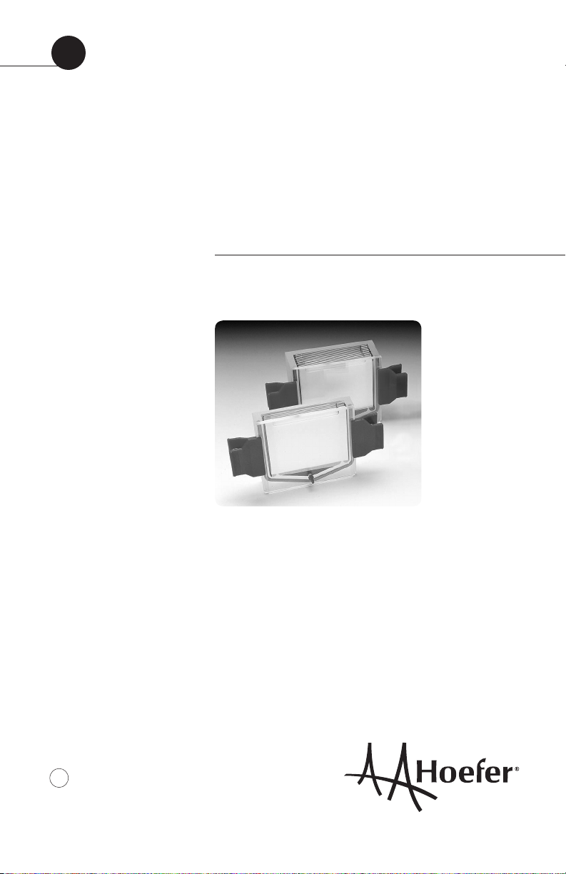
user manual
Hoefer Multiple
Gel Casters
SE215, SE235, and SE275
um SE215-IM/Rev.L0/08-12
Page 2

Contents
1. Multiple Gel Caster function ...............................1
2. Unpacking ........................................................ 2
3. Assembly ..........................................................2
Prepare the gel caster ........................................2
Construct the gel sandwich stack and
load into caster .................................................3
Prepare the monomer solution ............................6
Stacking gel preparation .................................... 8
Linear gradient gels ...........................................9
After Gel Polymerization ...................................12
4. Care and maintenance .....................................13
5. Troubleshooting ...............................................14
6. Ordering information ........................................ 16
pi
•
Page 3
1. Multiple Gel Caster function
Multiple gel casters prepare gels that are for
use in a Hoefer® miniVE, SE250 or SE260 gel
electrophoresis unit. The caster model selected
depends on the electrophoresis unit used and the
number of gels to be prepared:
Table 1: Multiple Gel Caster/electrophoresis
unit compatibility guide
for use with
Hoefer gel
gel plate electrophoresis
Gel caster no. of gels size (cm) unit:
SE215 4–10 10 × 8 SE250
SE235 2–4 10 × 10.5 SE260, miniVE
SE275 2–4 10 × 8 SE250
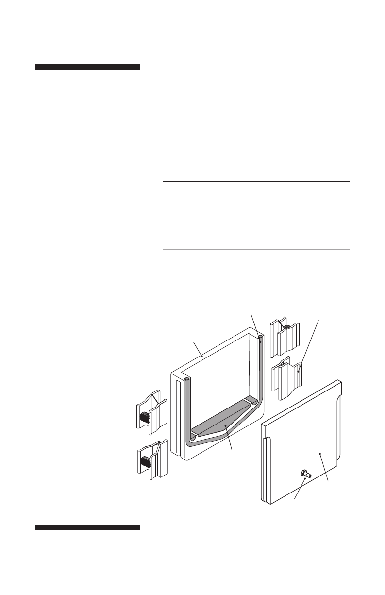
Fig 1. Multiple Gel Caster.
The faceplate seals against the
cylindrical silicone rubber gasket.
Included but not shown:
• Acrylic block
• Black vinyl cap for inlet port
• Polycarbonate filler sheets
• Glass and alumina plates
Accessories that may be
ordered separately:
• Combs
• Spacers
• Additional plates
Acrylic casting
chamber
Silicone rubber
gasket
Filler plugs
(1 large,
2 small)
Spring clamps
(2 or 4, depending
on model)
Inlet port
Faceplate
p1
•
Page 4

Note: Wear gloves to keep
the caster and plates free of
finger marks.
2. Unpacking
Unwrap all packages carefully and compare
contents with the packing list, making sure all
items arrived. If any part is missing, contact
Hoefer, Inc. Inspect all components for damage
that may have occurred while the unit was in
transit. If any part appears damaged, contact the
carrier immediately. Be sure to keep all packing material for damage claims or for repacking
should it become necessary to return the unit.
3. Assembly
All casters are assembled and used in the manner
described below. Both single concentration gel
and gradient gel instructions are included.
Prepare the gel caster
1
Prepare gel caster, plates and spacers by washing
with a mild detergent and rinsing thoroughly with
deionized water.
2
Periodically remove the U-shaped silicone rubber
gasket and inspect for nicks. If the gasket appears to
be intact, apply a light film of Gel seal lubricant to it
and replace: avoid stretching the gasket by laying it
onto the groove and pressing it into place. (Gel seal
is supplied with the SE250 and SE260 units.)
p2
•
Page 5
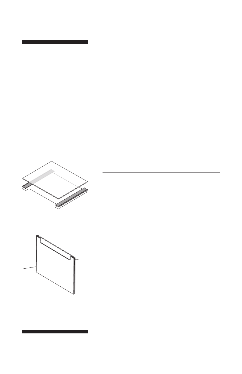
Fig 2. Location of T-shaped
spacers on notched plate.
3
Single-concentration gels — Plug the red inlet port
near the bottom of the faceplate with the black vinyl
cap included with the unit. Check that the two small
semi-circular and one large triangular rubber filler
plugs, which reduce the amount of solution needed
to fill the chamber, are properly seated in the bottom.
The crosswise groove in the plug distributes the monomer solution to all gel sandwiches so that they fill to
the same level simultaneously.
Gradient gels — Remove the large triangular plug.
Check that the two smaller rubber filler plugs are
properly seated in the bottom of the chamber. Refer
to page 9 for gradient casting instructions.
Construct the gel sandwich stack and load into caster
1
Construct each gel sandwich: For each sandwich,
choose one notched alumina plate, one rectangular
glass plate and two spacers. Use the same size spacers for each sandwich.
Lay the notched plate on a flat surface, place one
spacer along each edge so that it aligns with the
notch. Fit a glass plate onto the spacers as shown.
The stem of the T-shaped spacers fits between both
plates. The top of the T forms the edge of the gel
sandwich, (Fig 2).
(Alternatively, assemble the sandwich while it is in
a standing position.)
Fig 3. Align bottom edges of plates
and spacers carefully.
2
Pick up each sandwich and align both sides with the
spacers and also the bottom on a flat surface, (Fig 3).
•
p3
Page 6
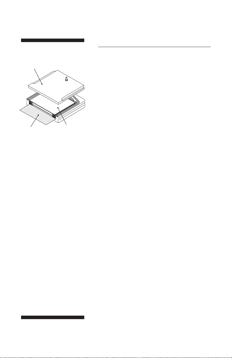
Face plate
Polycarbonate
sheet
Fig 4. Stack components
(Load from bottom up; Fillers are
added after sandwiches are in
place to adjust stack height)
• Polycarbonate sheet. (Acts as
lever for adding fillers below
the stack. Aids in inserting filler
blocks and disassembling the
stack.)
• Sheet of wax paper (not visible
on drawing). Repeat as needed
to fill the caster.
• Gel sandwich
• Face plate
Gel
sandwich
3
Build the stack in the caster.
(All components fit flush against the bottom and one
side.) Place a polycarbonate sheet in the caster so that
2/3 of the sheet lays within the caster and the rest
extends out of the top. (This will act as a lever when
inserting filler sheets once all sandwiches are in place.)
Place a sheet of wax paper onto the polycarbonate
sheet. (The wax paper makes it easier to disassemble
the stack.) Slide the first sandwich into the caster
along one side, notched plate side down and notched
side pointing toward the open end of the caster (top
when filled). Repeat with all sandwiches, building
the stack by layering sheets of wax paper and gel
sandwiches, all oriented the same way. Over the final
sandwich, lay a sheet of polycarbonate instead of wax
paper so that you can observe the liquid level when
pouring the gel solution, (Fig 4).
Notes:
• Inspect glass for nicks. Use only unchipped plates.
• Work on a flat surface for best results.
• Clean off the acrylamide film from both sides of
each polycarbonate sheet.
p4
•
Page 7

gel number
caster of clamps
SE215, SE275 2
SE235 4
4
If pouring fewer gels than the capacity of the caster,
lift up the polycarbonate sheet at the bottom of the
stack and slide in fillers such as the acrylic block,
polycarbonate sheets, or extra glass plates until the
stack is approximately 1 mm higher than the chamber
sides. (Once fillers are in place, slide the polycarbonate sheet in so that it is level with all other stack
components.)
(The stack must be slightly thicker than the space so
that the stack compresses slightly when the faceplate
is clamped in place. If the stack is too tall, a glass
plate may break or the caster won’t seal properly, but
if the stack is too short, the spacers may fall out of
alignment or the stack will not stay vertical.)
5
Lay the faceplate on the casting chamber, aligning it
so that is flush with all sides. Pick up the assembled
unit and check that the gasket compresses slightly.
6
Secure the stack with either 2 or 4 clamps (see
adjacent table). Open the jaws of the spring clamp,
then position the longer side jaws on the faceplate.
When the clamp is released, the short jaw seats in the
groove on the casting chamber side and the long jaw
seats in the groove on the faceplate.
2 clamps — position each clamp in the middle of
the faceplate.
4 clamps — Slide the top clamp upward to fit
against the end of the groove on the front panel.
7
Stand the assembled caster upright and inspect.
Check that the gasket forms a tight seal and is not
unduly deformed. Check that the stack fits snugly and
that the plates and spacers are still aligned; adjust
if necessary.
p5
•
Page 8

Prepare the monomer solution
1
Prepare enough monomer solution to fill all sandwiches to the level of the notched plate (or lower
if a stacking gel or first dimension IPG strip will be
added — see step 2). The formula below allows extra
solution to fill the space between the sandwich and
the chamber.
Table 2: Variables for calculating monomer volume
gel caster area X cm2 extra vol. required (Y ml)
SE215 60 11
SE235 80 8
SE275 60 5
Monomer = area X × spacer × total gel + extra chamber
vol (ml) (cm2) thickness (cm) sandwiches vol (Y ml)
An example volume calculation for the SE215 for 10 sandwiches, each with a thickness of
1.5 mm follows: From Table 2, the area variable for the SE215 is 60 and the extra volume
variable is 11 ml.
(60 cm2) (0.15 cm) (10 sandwiches) + 11 ml extra volume required = 101 ml
p6
•
Page 9

Note: Avoid repeated and
prolonged contact of
n-butanol with the acrylic
casting chamber to prevent the
acrylic from becoming opaque.
2
Deaerate the monomer solution and add the initiator
and catalyst just prior to pouring the gel. Fill the solution into only one sandwich, allowing the groove in the
bottom plug to distribute the solution evenly between
all sandwiches. (Pouring into more than one sandwich
could introduce air pockets.) Watch the solution level
through the faceplate. See below for the appropriate
solution level according to the application.
No stacking gel
Fill with solution to just below the top of the notched
plate. If air pockets form, remove them with a pipette or
syringe. Introduce a comb (at a slight angle) into each
sandwich, taking care not to trap air under the teeth.
Stacking gel
Fill with solution to 3 cm below the top of the rectangular glass plate. This height allows 1 cm of stacking
gel below the wells. Pour the gel and apply an overlay.
(See step 3.) After the gel is set, prepare the stacking
gel as described below.
2-D electrophoresis
Fill with solution to about 1 cm below the top of the
rectangular glass plate. This height allows 4 to 5 mm
of space for the IPG Strip and an agarose seal). Overlay the separating gel as described in step 3.
3
If casting polyacrylamide gels, overlay each gel with
a thin layer of water-saturated n-butanol, water, or
diluted gel buffer to prevent gel exposure to oxygen.
Apply the same amount to each gel to keep the gel
levels the same. Deliver the overlay solution slowly
near the spacer at the side of the sandwich. Allow the
solution to flow across the surface unaided.
4
Allow the gel to polymerize for a minimum of 1 hour.
See page 12 for stack disassembly.
•
p7
Page 10

Important! For optimal gel
performance, cast stacking gels
just prior to use.
Stacking gel preparation
Add a stacking gel to as many gels as required
either individually to each gel after it is transferred to the electrophoresis unit (see instructions with unit), or to the whole stack of gels
while it is still in the caster. To pour stacking
gels in a multiple gel caster:
1
Rinse off the overlay with distilled water. Invert the
casting chamber to drain.
2
Calculate the stacking gel monomer solution volume
(ml): measure the distance, in cm, from the top of
the resolving gel to the notch in the notched plate.
Multiply this distance by the gel width (8 cm), the gel
thickness (cm), and the number of gel sandwiches.
Add the extra volume required for the caster model
used. (Variable Y in Table 2.)
3
Prepare the stacking gel monomer solution, deaerate
it, and add catalyst and initiator. Gauge the amount of
volume required to fill the sandwich to the notch by
adding the stacking gel with a Pasteur pipette to the
first sandwich, which is visible through the faceplate.
Then add the same amount of monomer solution to
each sandwich, working fairly rapidly.
4
Once all stacking gels are poured, insert a comb (at
a slight angle to prevent trapping air) into the front
sandwich, allowing the comb sides to rest on the
spacers. Insert the remaining combs from front to
back in the same manner. Allow a minimum of one
hour for the gels to polymerize. See page 12 for
stack disassembly.
p8
•
Page 11

Fig 5. Gradient maker set-up.
Attach tubing to inlet port of the
multiple gel caster, run the tubing
through a peristaltic pump, and
attach to gradient maker.
Linear gradient gels
Gradient gels are prepared by first pumping the
“light” (lower % acrylamide) solutions and then
gradually adding a “heavy” (higher % acrylamide) into the caster by way of the inlet port
on the faceplate.
1
Follow instructions for preparing the gel caster on
page 2. Remove only the triangular rubber plug from
the bottom of the casting chamber, leaving the two
smaller plugs in place.
2
Follow the instructions for constructing the gel sandwich stack and loading it into the caster on page 3.
3
Connect the gradient maker to the gel caster. Run
a length of clear vinyl tubing through a peristaltic
pump and attach one end of the tubing to the gradient maker outlet port and the other end to the casting
chamber inlet port on the faceplate. Adjust the pump
to run a rate of about 5 ml/min for 4-gel casters and
about 10 ml/min for 10-gel casters.
Mixing chamber
Multiple gel caster
Gradient maker
Peristaltic pump Magnetic stirrer
p9
•
Page 12

Note: 15% solid sucrose (w/v)
or 25% glycerol (w/v) in the
“heavy” solution minimizes
mixing and aids gradient
layering.
gel caster required volume gradient maker
range (ml) size*
SE215 55 –100 SG100
SE235 32– 56 SG50 or SG100
SE275 22– 40 SG30 or SG50
*Actual size depends on calculated volume.
4
Prepare solutions
Plug solution
Prepare enough plug solution (50% sucrose or 75%
glycerol in 1X separating gel buffer) to fill the space
below the sandwiches. The SE215 requires about
30 ml and the SE235 or SE275 requires about
15 ml. The plug solution is pumped in after the gradient to displace all of the monomer solution into the
sandwich stack.
Optional: Add bromophenol blue to help track the
plug as it is pumped into the multiple gel caster.
Monomer solution
Follow the instructions on page 6, step 1 for
calculating the total volume of monomer solution
needed. Divide the total volume in half and prepare
this volume of each of the higher and lower %
acrylamide solutions.
•
5
Pour the “heavy” solution into the reservoir chamber
(the chamber furthest from the outlet). Open the stopcock long enough to displace air in the connection
between the chambers and then close. Fill the light
solution into the mixing chamber and place a stirring
bar in this chamber. Place the gradient maker on a
magnetic stirrer and begin stirring at a rate that does
not introduce bubbles into the solution.
p10
Page 13

Note: Avoid repeated and
prolonged contact of
n-butanol with the acrylic
casting chamber to prevent the
acrylic from becoming opaque.
6
Mix the gradient and pump the solution into the caster.
While the solution is stirring, begin pumping from the
mixing chamber and open the stopcock to the reservoir chamber. As the last of the monomer solution is
leaving the mixing chamber, pour the plug solution
into the mixing chamber, leaving no opportunity for
air pockets to form in the tubing. Watch for the plug
solution to approach the bottom of the sandwiches (do
not pump plug solution into the bottom of the sandwiches) then turn off the pump and clamp the tubing
so that no air enters the gel caster.
7
Overlay each gel with a thin layer of water-saturated
n-butanol, water, or diluted gel buffer to prevent
gel exposure to oxygen. Apply the same amount to
each gel to keep the gel levels the same. Deliver the
overlay solution slowly near the spacer at the side of
the sandwich. Allow the solution to flow across the
surface unaided. Apply the same amount to each gel
to keep all gel levels equal.
8
Allow the gels to polymerize for a minimum of one
hour. Open the casting chamber over a sink and
discard the plug solution.
•
p11
Page 14

Note: Do not store gels in the
caster because they will be
difficult to remove.
After Gel Polymerization
1
To remove combs (if necessary): cover each sandwich
with several ml 1X electrophoresis buffer, then work
each comb out slowly by gently rocking it side to side
while pulling it out.
Remove the gel stack from the casting chamber. Take
care to keep the spacers in place while separating
sandwiches: Slip a razor blade between the first two
sandwiches and gently pry the top sandwich loose.
Remove the wax paper between each sandwich.
2
Rinse each sandwich with distilled water to wash off
the overlay and remove any extra gel adhering to the
plates, then blot dry.
3
To use gels — Follow instructions accompanying the
electrophoresis unit.
To store unused gels — Add approx. 5.0 ml of 1X
separating gel buffer to the top of each sandwich,
seal with plastic wrap, and lay flat in refrigerator set
to 4 °C. Or, lay gels flat, submerge in 1X separating
buffer, and store refrigerated. Use within 1 week.
•
p12
Page 15

4. Care and maintenance
Important! Never autoclave any
casting kit component.
Clean the unit with soap and water after each
use and rinse thoroughly with distilled water.
Never use abrasive cleansers. Do not expose
the unit to solutions or vapors of aromatic or
halogenated hydrocarbons, ketones, esters,
alcohols (over 30%), or concentrated acids or
bases (over 25%). All components are resistant
to common electrophoresis buffers.
Clean glass plates with a mild laboratory detergent such as Pierce RBS-35®.
•
p13
Page 16

5. Troubleshooting
problem solution
Plates broken Stack may be too tall. Before clamping, check that
the stack is about 1 mm higher than the top of the
caster edge.
Check that all spacers and plates are aligned before
applying the clamps.
Notched plate ears broken Avoid stressing the ears by only handling the sand-
wiches by the sides and bottom.
Separate sandwiches along the bottom of the stack.
Caster leaks Apply a light film of Gel seal to the gasket each time
the unit is used.
Check the foam gasket for cracks or nicks and replace
if necessary.
If the stack is too tall, the front plate may not seat
firmly against the gasket. Remove filler plates until
the stack seals.
Gel heights uneven Pour the monomer solution into only one sandwich
and allow the groove in the triangular plug to evenly
distribute the solution.
Make sure the groove in the triangular plug is clean
and clear of material.
Wait one minute before overlaying each gel so that
the solution “settles”. Then add the same amount of
overlay solution to each sandwich.
•
p14
Page 17

problem solution
Sample wells damaged or leak Remove air pockets before inserting combs. Slide comb
into solution at an angle. If comb must be removed,
add more monomer solution before reinserting the comb.
Allow the gel to set for a minimum of 1 hour.
Remove the comb at a slight angle and very slowly to
prevent the gel from becoming damaged.
Degas stacking gel solution.
Increase catalysts up to 0.1% v/v TEMED,
0.1% v/v APS.
Gel sandwiches separate Place wax paper between sandwiches in the stack and
in the back of the caster so that sandwiches separate
easily from each other. (This reduces any tendency
for plates to stick to each other instead of to the gel.)
Also, place a polycarbonate sheet on the top of the
stack to prevent a vacuum from forming between the
glass and acrylic face plate.
Gradient gels — uneven layering Add sucrose (15% final concentration) or glycerol
(25% final concentration) to the high percent monomer solution.
Add a small amount of bromophenol blue to the heavy
solution to track the gradient formation.
Decrease the pump rate.
•
p15
Page 18

6. Ordering information
product quantity code number
Gel Casters
For 10 × 8 cm gels
SE275 4-Gel Caster, complete (10 × 8 cm), 2– 4 gels. SE275
Includes 4 notched alumina plates, 10 rectangular glass plates,
2 red clamps, 100 sheets wax paper, space-saver plate,
5 filler sheets, set of filler plugs and Spacer-Mate assembly
template. (Order combs and spacers separately.)
SE215 Multiple Gel Caster, complete (10 × 8 cm), up to 10 gels. SE215
Includes 10 notched alumina plates, 20 rectangular glass plates,
2 red clamps, 100 sheets wax paper, space-saver plate,
5 filler sheets, set of filler plugs and Spacer-Mate assembly
template. (Order combs and spacers separately.)
For 10 × 10.5 cm gels
SE235 4-Gel Caster, complete (10 × 10.5 cm), 2– 4 gels. SE235
Includes 4 notched alumina plates, 5 rectangular glass plates,
4 red clamps, 100 sheets wax paper, space-saver plate,
5 filler sheets, set of filler plugs and Spacer-Mate assembly
template. (Order combs and spacers separately.)
Accessories and replacement parts
Wax paper, precut sheets, for SE275 and SE215 100/pk SE201
Wax paper, precut sheets, for SE235 100/pk SE231
Silicone rubber filler plug set for SE215 3/pk SE209
Filler plug set for SE235 and SE275 SE279
Filler sheets, for SE275 and SE215 5/pk SE213
Filler sheets, for SE235 5/pk SE233
Space-saver plate, for SE215 and SE275 1 SE217
Space-saver plate, for SE235 1 SE237
•
p16
Page 19

product quantity code number
Clamps
Red clamps with springs, 4/pk SE252
for use on SE250, SE260 and on gel casters.
Spacers
thickness width
(mm) (cm) quantity code number
For SE250 0.75 8 2 SE2119T-2-.75
1.00 8 2 SE2119T-2-1.0
1.50 8 2 SE2119T-2-1.5
For SE260 and miniVE 0.75 10.5 2 SE2619T-2-.75
1.00 10.5 2 SE2619T-2-1.0
1.50 10.5 2 SE2619T-2-1.5
Glass and alumina plates
For SE250 (10 × 8 cm)
Notched glass plates 5/pk SE202GN-5
Notched alumina plates 10/pk SE202N-10
Rectangular glass plates 10/pk SE202P-10
For SE260 and miniVE (10 × 10.5 cm)
Notched glass plates 5/pk SE262GN-5
Notched alumina plates 5/pk SE262N-5
Rectangular glass plates 5/pk SE262P-5
•
p17
Page 20

Combs
no. of wells thickness (mm) width (mm) quantity code number
5 0.75 13.0 1 SE211A-5-.75
5 1.00 13.0 1 SE211A-5-1.0
5 1.50 13.0 1 SE211A-5-1.5
*9* 1.00 5.8 1 SE211A-9-1.0
10 0.75 4.8 1 SE211A-10-.75
10 1.00 4.8 1 SE211A-10-1.0
10 1.50 4.8 1 SE211A-10-1.5
12 1.00 4.75 1 SE211A-12-1.0
15 0.75 2.9 1 SE211A-15-.75
15 1.00 2.9 1 SE211A-15-1.0
15 1.50 2.9 1 SE211A-15-1.5
18* 1.00 2.9 1 SE211A-18-1.0
1/1† 0.75 68/5 1 SE211A-R-.75
1/1† 1.00 68/5 1 SE211A-R-1.0
1/1† 1.50 68/5 1 SE211A-R-1.5
*Microtiter spacing
†
Preparative/reference well
Gradient makers
volume (ml) chamber ID (cm) quantity code number
SG15 15 1.27 1 SG15
SG30 30 1.58 1 SG30
SG50 50 1.91 1 SG50
SG100 100 2.54 1 SG100
p18
•
Page 21

Hoefer, Inc.
84 October Hill Road
Holliston, MA 01746
Toll Free: 1-800-227-4750
Phone: 1-508-893-8999
Fax: 1-508-893-0176
E-mail: support@hoeferinc.com
Web: www.hoeferinc.com
Hoefer is a registered trademark
of Hoefer, Inc.
RBS-35 is a trademark of Pierce
Chemical Co.
© 2012 Hoefer, Inc. —
All rights reserved.
Printed in the USA.
 Loading...