

Page 1
Page 2

Page 3
1
Contents
Contents
Please Read First
Standard Package Contents
The Hand Unit
The Receiver Unit
The HPM-1 Motor and Extras
Getting Started
Mounting the HPM-1
Setting the channel
Checking the Signal Strength
Lens Calibration and Direction Changing
Soft Stops
Run/Stop
Power
Innite Rotation Mode
Complience
Connector Pinout
LED Display Key
..............................................1
....................................2
......................3
.......................................5
...................................7
.....................9
....................................11
.............................13
...............................14
..................15
...17
...........................................18
............................................19
................................................21
...........................23
.........................................24
.................................25
....................................26
Page 4
2
- Do not overtighten any rod clamps or tighten with no rods
inserted
- Do not press on the membrane panel lights (Limits, Run, Inf.rot)
- Do not operated in excessively wet enviroments
- When inserting Lemo connecters, alighn the red dots DO NOT
BLINDLY MASH CONNECTOR INTO SOCKET
- When not in use for long periods of time, remove battery from the
hand unit
- Do not attempt to use with high gain antennas
- Ensure the right antennas are used, articulated antenna on the
receiver, short straight antenna on the hand unit.
- Do not attempt to open any of the units unless instructed to do so
by Hocus Products. Doing so could void your warrenty
- To clean the units, wipe with a damp cloth
- Always transport in a rigid bodied case
- Check the manufacturers guidelines for battery information.
- Do not dispose of units in house hold waste
- Even though the Axis1 is ROhS compliant, do not attempt to eat
any part of your Axis1 unit
Please Read First
Page 5
3
Package Contents
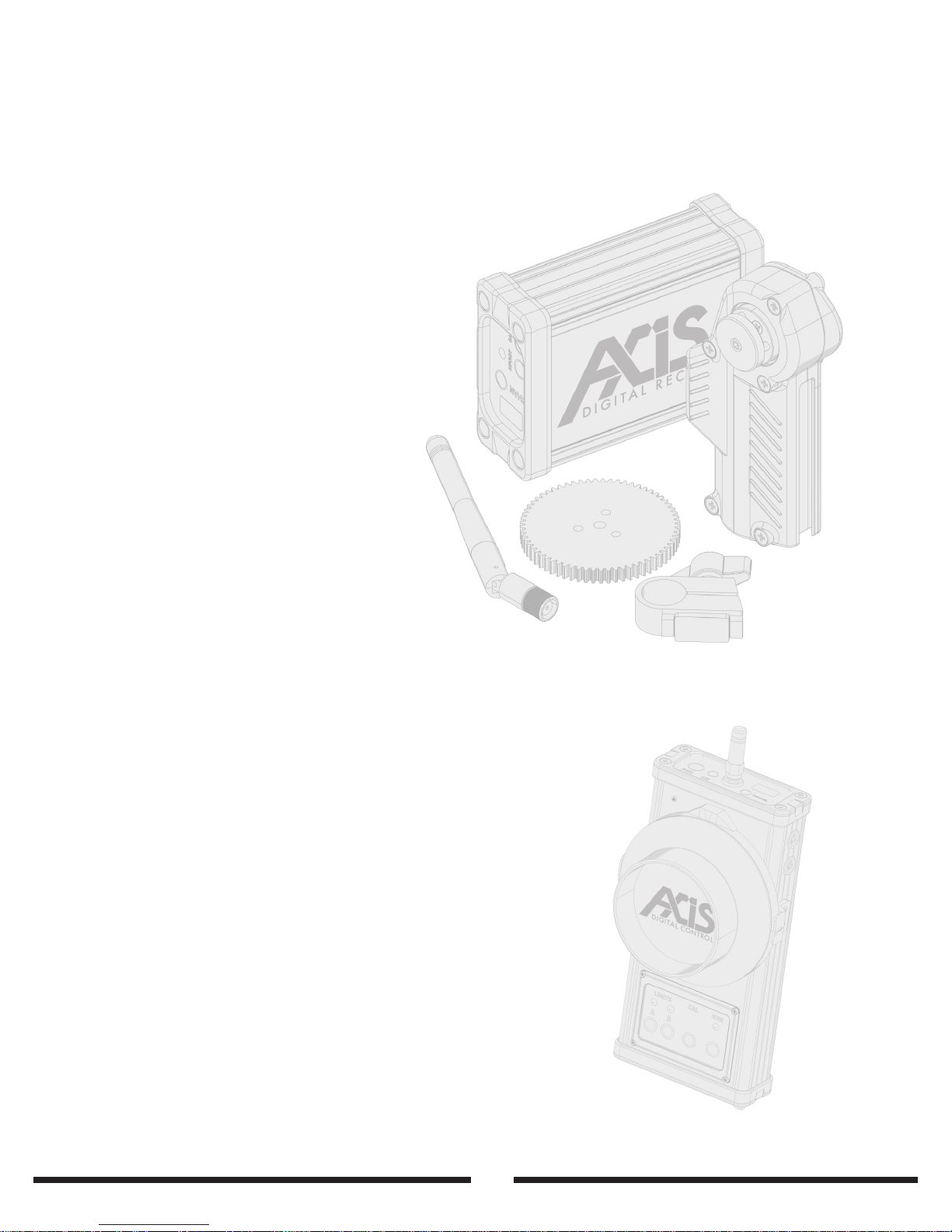
• Receiver unit
• Hand unit
• HPM-1 motor
• Drive gear
• Motor clamp
• Marking ring
• Motor cable
• Power Cable
• USB Update cable
• Antennas
• LED Focusing light
• Motor Cables (Varying lengths)
• Camera specific run cables
• Motor mounts (different sizes available)
• Additional marking rings
• Storm Case with custom cut foam
• Motor Drive gears (Various pitches available)
• Receiver mounting devices
• Spare hub nut, antennas, USB update cables
Standard Package Contents
Optional Extras
Page 6
4
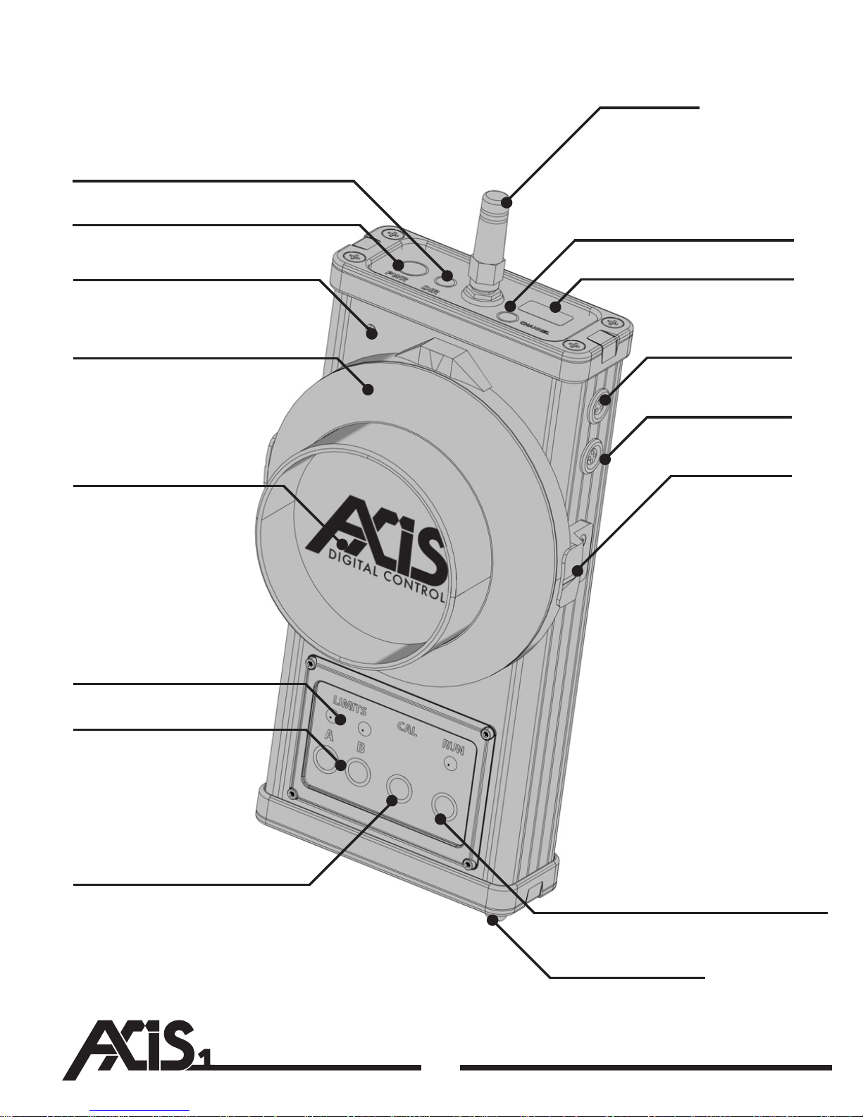
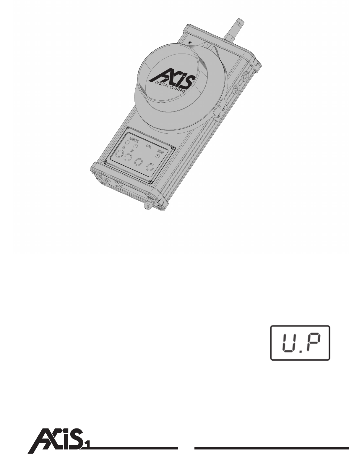
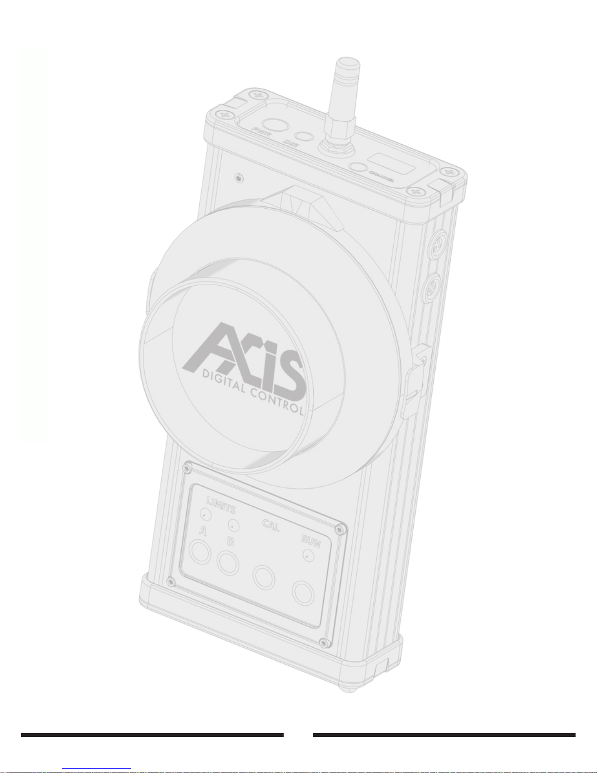
Direction Button
Power Button
Indicator Light
Control Wheel
Removable Marking Ring
Limit Set Buttons
Lanyard Stud
Limit Set Indicators
Antenna
Channel Change
LED Display
Light Socket
BUS Port
Side Pointer
Autocalibrate Button
Run Button And Indicator
Page 7
5
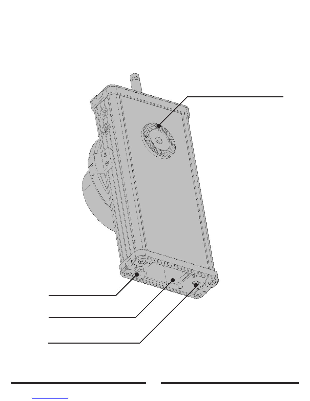
The Hand Unit
ARRI Standard Rosette (M6)
Lanyard Stud
Battery Compartment
Battery Release Lever
Page 8
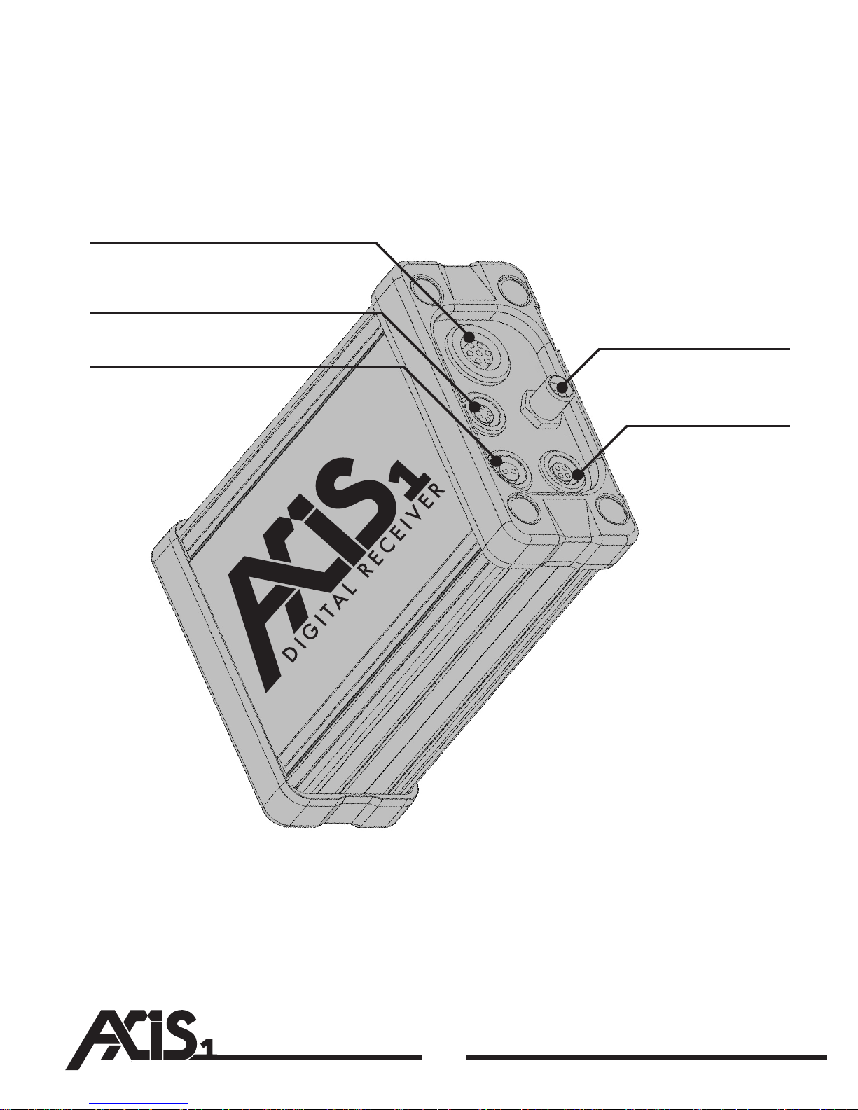
Camera Run Connector
6
Motor Connector
12v DC Power Connector
BUS Connector
Antenna Connector
Page 9
7
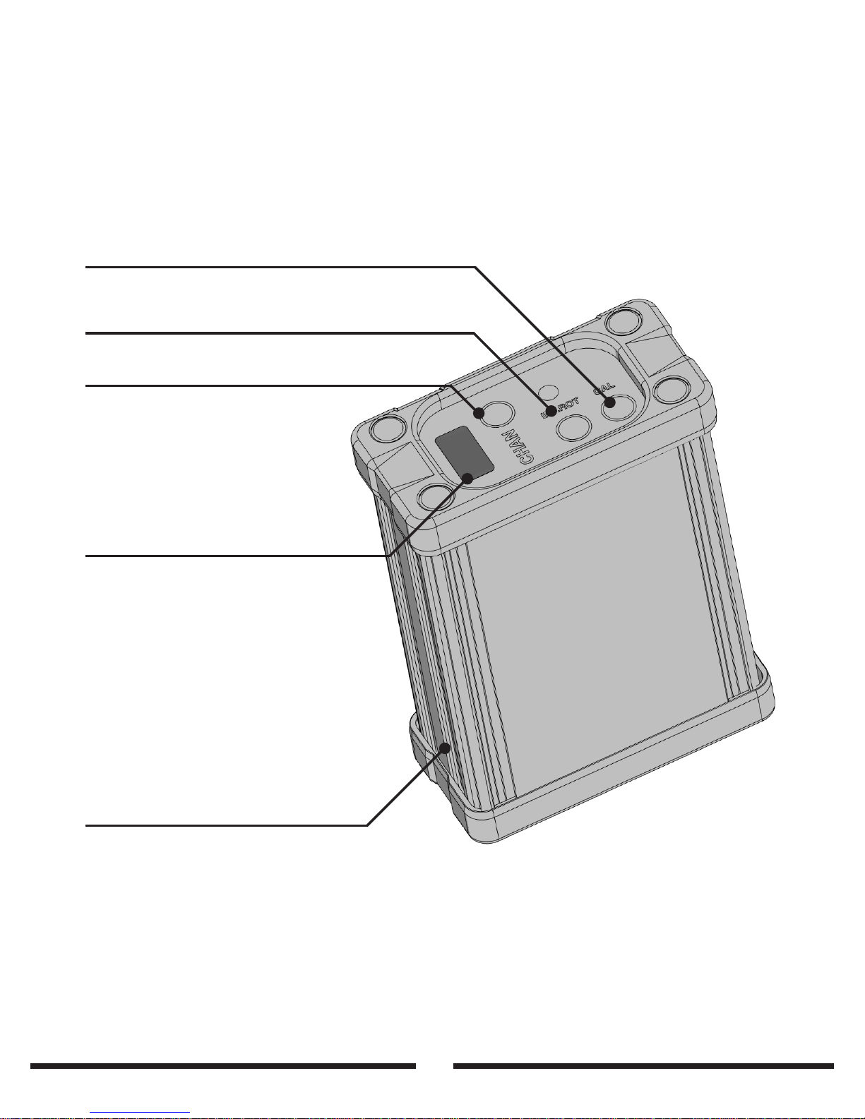
The Receiver Unit
Autocalibrate Button
Innate Rotation Button And Indicator
Channel Button
LED Display
Mounting Rails
Page 10
8
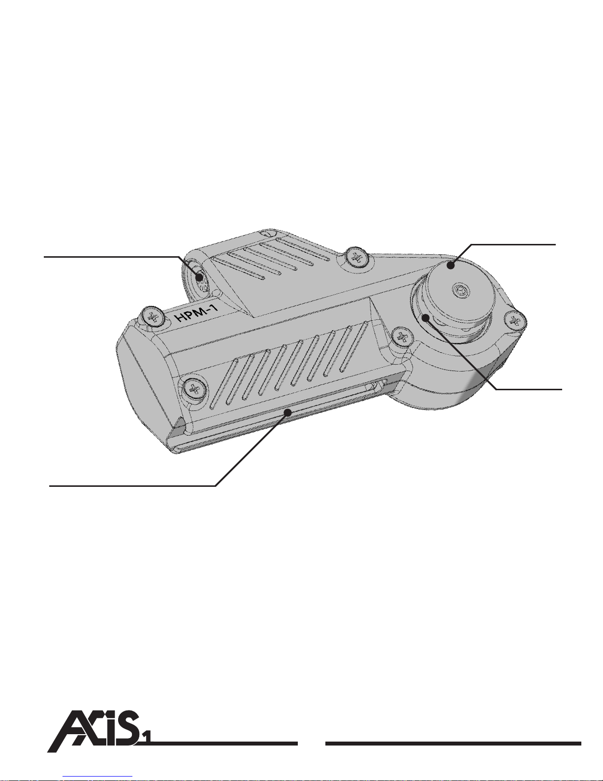
Sliding Motor Mount Rail
Hub Screw
Controller Connector
Gear Hub
Page 11
9
The HPM-1 Motor and Extras
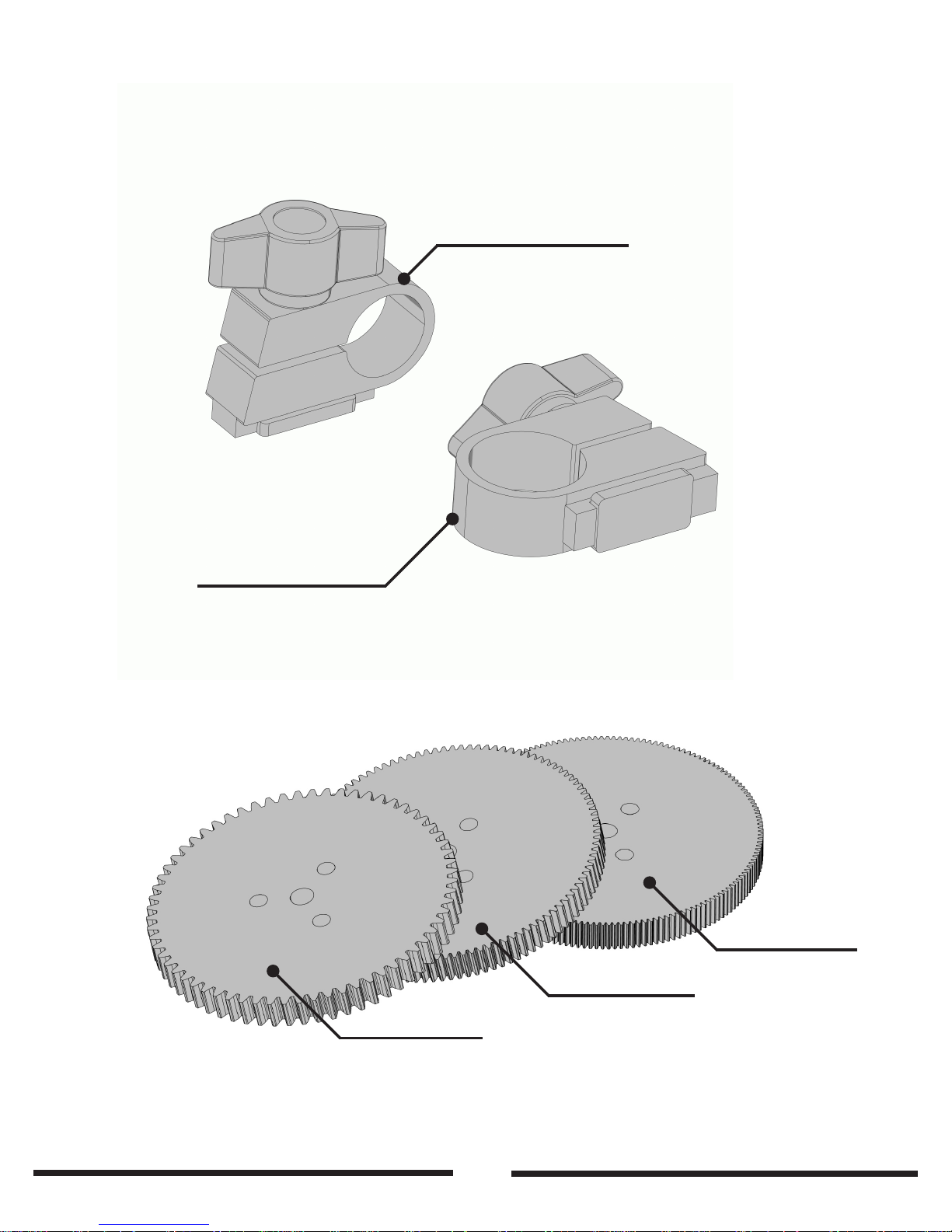
0.8 Mod Gear
0.6 Mod Gear
0.5 Mod Gear
19mm Rod Clamp
15mm Rod Clamp
Page 12
10
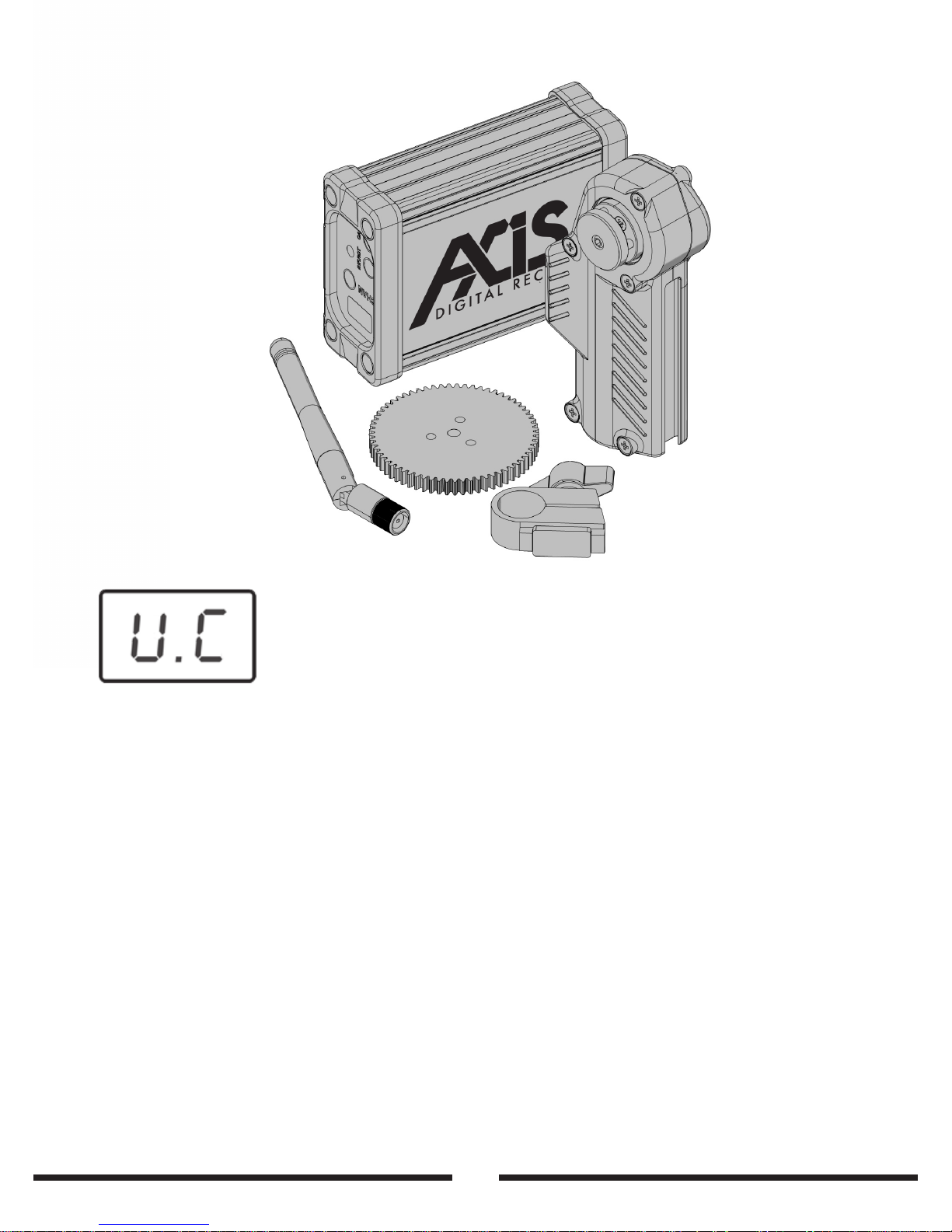
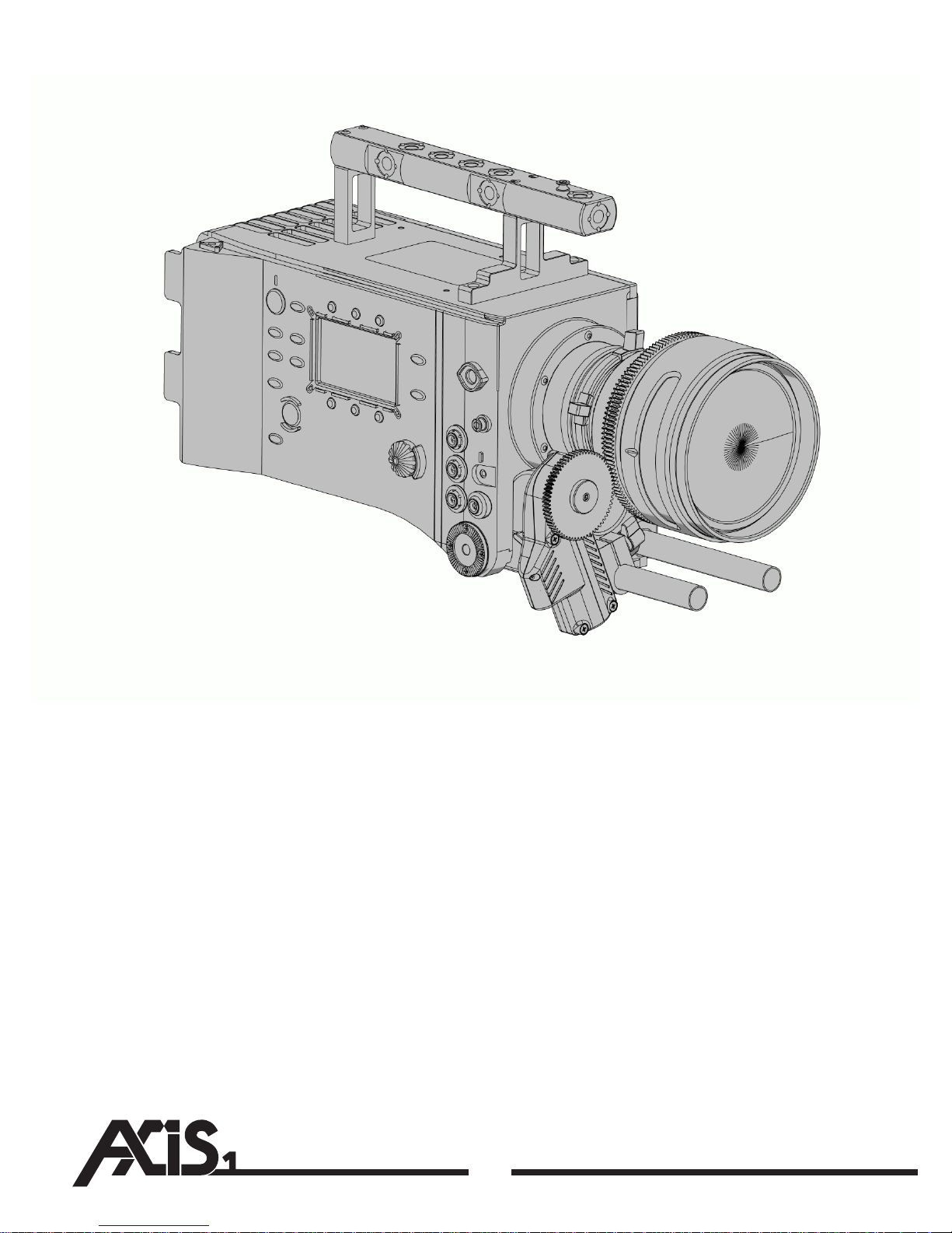
The Axis1 consists of three main components; The hand unit, the receiver and
the motor.
Mount the receiver unit on your camera. Using Velcro or Tu Lock is acceptable,
or you can use one of the receiver rod mount accessories available from Hocus
Products. Use the long articulated antenna with the receiver unit. Bend the
antenna up so it is out of the way of the Lemo connectors. Provide power to the
receiver using the supplied power cable. It is advised that power is taken
directly from a battery using a Dtap or similar.
Insert a suitable battery (Canon LP-E6) into the hand unit and switch on using
the PWR button on top of the unit. Use the short antenna with the hand unit.
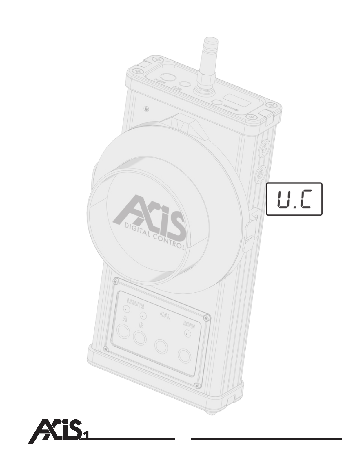
Powering the receiver unit will switch it on (there is no power
on o switch). The LED display on the unit will ash U.P for
motor unplugged, or no motor present. The display will ash
U.C for uncalibrated if a motor is found.
MOTOR
UNPLUGGED
Page 13
11
Getting Started
DO NOT DO THIS IF YOU ARE USING A ENDLESS INFINATE ROTATING DSLR LENS.
SEE THE INFINATE ROTATION SECTION OF THIS MANUAL FIRST.
The motor will calibrate torque and end limits. If there is no hand unit present,
the motor will sit at the end of the lens and await signal from a hand unit. If the
hand unit is switched on and is operating on the right frequency (see
frequency changing section of this manual) then the system will go into live
control mode.
If the receiver unit looses power for less than ve minutes (a battery change for
example) then it will not require recalibration. Please remember that if the
motor is removed and replaced, or the lens is changed a recalibration must be
performed for proper operation. To do this, the calibrate button on either the
receiver or hand unit can be used.
Plug the motor into the receiver unit. The display will ash
U.C for uncalibrated. Mesh the motor with the lens and
press and hold the calibrate button and the auto calibrate
sequence will initiate.
UNCALIBRATED
Page 14
•
12
The motor features a sliding rod mount slot so the motor can be height adjusted
to achieve convenient mesh with the lens. There are 15 and 19mm rod mounts
available. Slide the mount in to the slot, either way up (the clamp can be used
upside down so that the tightening knob is in a convenient place.) It is not
necessary to clamp the rod mount too tightly, nger tight will do. Over tightening
can cause damage to the clamp. Please be aware if the motor swings away from
the lens easily, it may be the entire rod rotating and not the motor clamp slipping.
Check that the rod is not rotating in whatever clamp it is held in before tightening
the motor clamp.
Select the correct drive gear and install onto the motor hub by removing the hub
screw and sitting the gear on over the three locate pins. Replace the screw and
tighten.
Page 15
13
Mounting the HPM-1
Mesh the motor gear to the lens. It is not important where the lens is in its range,
there is no need to ensure the lens is in the middle or away from either of the
stops. It is important to ensure that that is a small amount of backlash between
the motor and the lens. This ensures smooth running of the system.
If you are using third party gear rings on SLR lenses, please ensure that the gears
are concentric to the lens. If there are any centreing problems, this can cause a
cam eect and push the motor away from the lens which can cause backlash or
tooth skipping.
The motor can be mounted facing away or upside down or coming up from
under the lens. The direction can be set up on the hand unit so the motor always
turns the lens the way you expect.
PLEASE NOTE:
If the original hub screw is lost for any reason the thread in the centre of the hub
is metric standard M4. Any M4 screw up to about 14mm long can be used to hold
the gear on if the original screw is lost. New screws can be obtained from Hocus
Products ora ny of our dealers.
Page 16
14
Setting the Channel
Setting the Channel
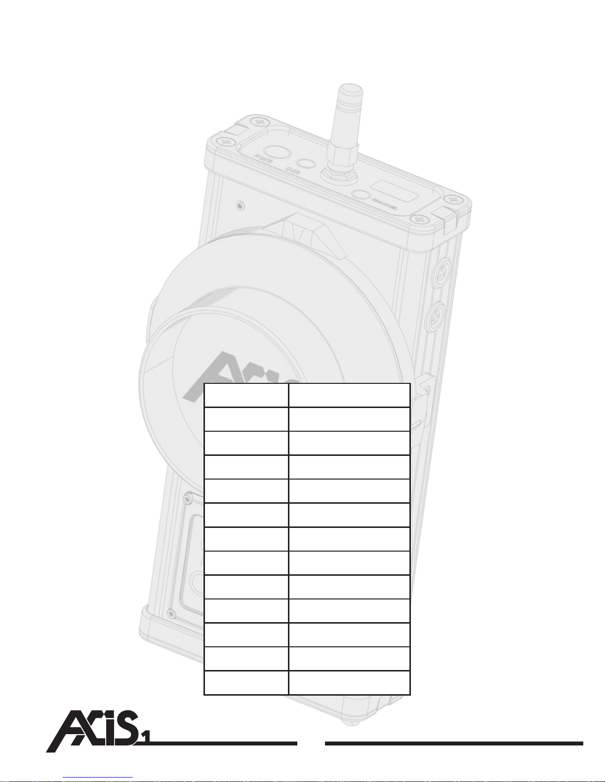
The Axis1 operates on a secure digital 2.4ghz wireless link. This is not the same as
Wi, Bluetooth or Zigbee (no hopping). There are 12 user denable channels that
can be changed using the CHANNEL button on either the receiver or the
transmitter. The channel changing process is the same on both units.
To verify the current channel on the hand unit, momentarily press the CHANNEL
button. The current frequency is displayed, followed by a signal strength report.
Please see the Checking Signal Strength section of this manual for more
information. The current frequency will show (please note the frequency is
permanently displayed on the receiver). To change the channel, press and hold
the CHANNEL button. After a few seconds, the current channel number will begin
to ash. Pressing the channel button will now incrementally increase the channel
number by one. After channel 12, the number will loop back to 1. Once the
desired channel is selected and is showing on the display, let go of the button and
after a few seconds the new frequency will be selected. A list of channels and
their actual frequencies is listed below.
Channel
1
2
3
4
5
6
7
8
9
10
11
12
Frequency
2.410ghz
2.415ghz
2.420ghz
2.425ghz
2.430ghz
2.435ghz
2.440ghz
2.445ghz
2.450ghz
2.455ghz
2.460ghz
2.465ghz
Page 17
15
Checking the signal strength
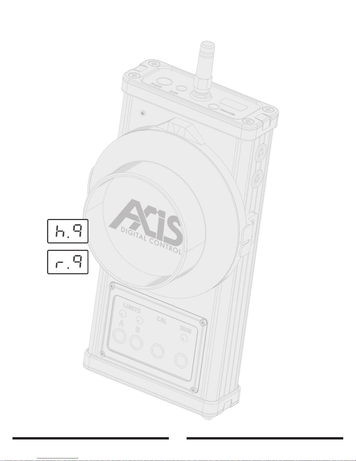
A signal strength report is automatically displayed on the hand unit LED display
after a channel check. To check the signal strength, press the channel button and
the current channel will be displayed, followed by the signal strength report,
which is shown in the form of two numbers, h0-9 (signal being received by the
hand unit) and then r0-9 (signal being received by the receiver)
We recommend that you try not to use the unit if the signal is below 2 as this
could cause undesired operation.
This is useful if you are operating in the upper limit of the systems range, you can
use these two values to determine which unit needs adjusting to gain better
signal.
Checking signal strength
Signal being received by hand unit - level 9 (full signal)
Signal being received by receiver unit - level 9 (full signal)
Page 18
16
Lens Calibration
To initiate an auto calibrate routine, press and hold either of the two calibrate
buttons. There is a calibrate button on both the hand unit, and the receiver unit.
The Axis1 features a very advanced lens calibration system that not only
calibrates the movement range of the lens, but also the required torque level as
well. To initiate a calibrate sequence, press and hold either calibrate button, either
on the transmitter or receiver. If the receiver looses power for 5 minutes or less, it
is assumed that a battery change or similar has taken place and the lens or
camera setup has not changed, so a recalibrate will not be required to return to
operation. If more than 5 minutes has elapsed since the unit was powered o, it is
assumed the camera setup has been changed, and the receiver unit will require a
recalibrate by pressing and holding either of the calibrate buttons.
When setting up the system, there is no need to think about knob or lens
position. There is no need to position the lens in the middle of its rotation. The
Axis1 calibration system is intelligent enough to realise when it starts the routine
up against a lens stop, and it can work around this. Simply mesh the lens and the
gear together with the lens and focus knob in any position and press and hold the
calibrate button. The motor will quickly calibrate torque level required and range
of motion, then the system will be ready to use. You will notice how quickly the
calibrate sequence is, and that there is no lingering or pushing on the end stops.
The calibrate routine is sensitive enough to be able to lightly ‘bounce’ o the
stops applying very little force to the lens. This is particularly useful when using
smaller cameras such as DSLRs which tend to bend and ex when force is applied
to the stop.
If at any time a recalibrate is required, the LED displays on
both units will ash U.C (Uncalibrated). A recalibrate routine
can be triggered at any time with either of the two calibrate
buttons.
UNCALIBRATED
Page 19
17
Lens Calibration and Direction Changing
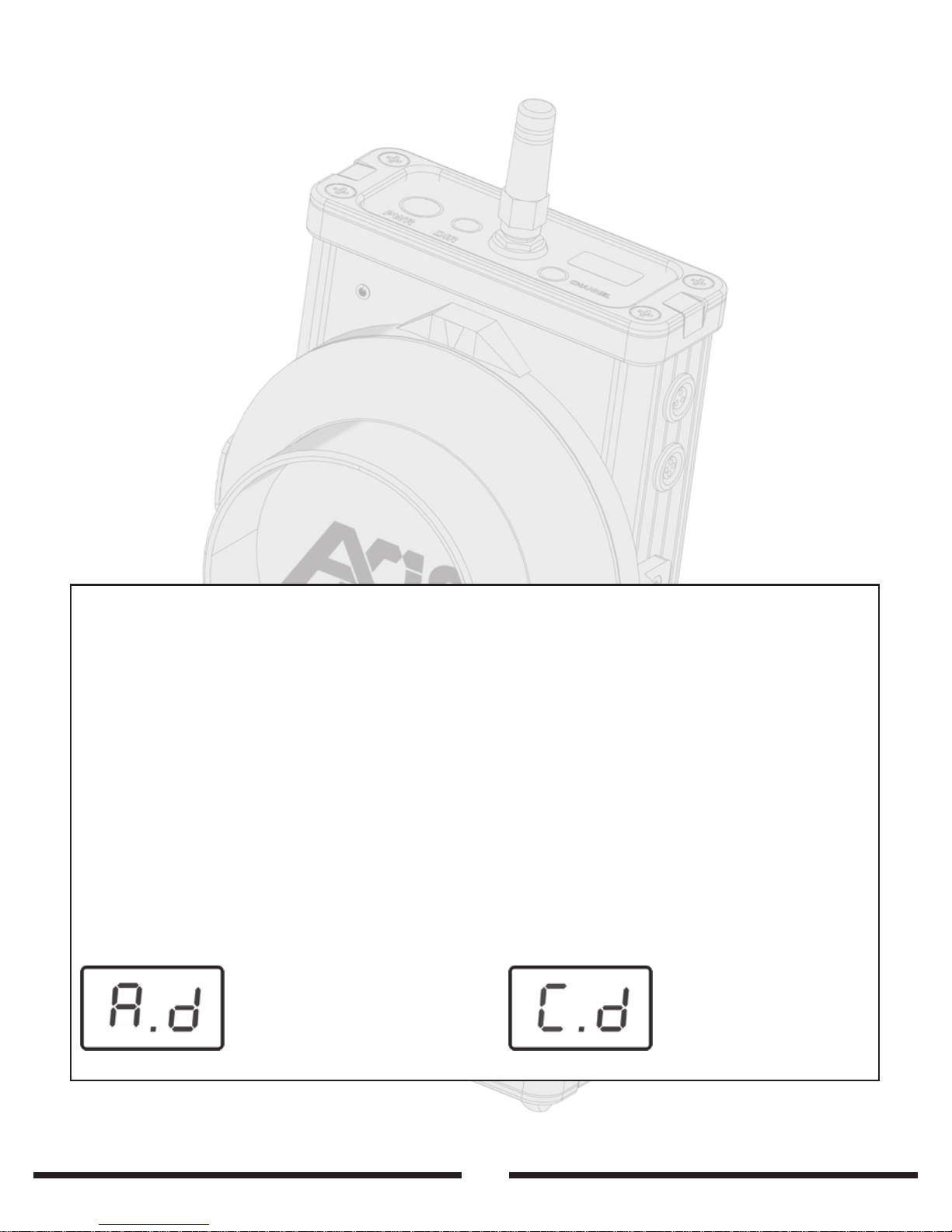
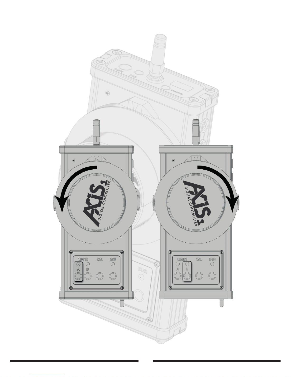
To change the direction of the motor in relation to the control knob, press the DIR
button on the controller. This will toggle the direction between C.d (clockwise
direction) and A.d (anti clockwise.) Please bear in mind that the direction the lens
moves in relation to the knob will change depending on the mounting of the
motor, the side the motor is on and which way the motor is facing. Also please
note that when changing the direction, the A/B limits if set will also change, to
take into account the new direction of travel.
When the direction is changed, the marks on the marking ring will reverse, so if
you mark a lens up and then change direction, the marks will no longer line up.
Please also note, as the system calibrates torque as well as limits, if the motor is
ever hand calibrated (stopping the motor spinning by hand to simulate motor
end stops) the system is essentially calibrating to zero extra torque, as the gear is
spinning in free space. This will make the motor appear very weak and easy to
stop. This is normal and is a sign that the auto torque calibration is working properly.
As with any remote or manual follow focus, some lenses and cameras will require
long lens supports, such as CP.2 lenses mounted via the EF mount on Canon
DSLRs. Please ensure that the lens has sucient support and is tight in the mount.
If the lens can rotate slightly in the mount then this can cause repeatability issues
with stops. It is especially important to help the lens stay in the right orientation
with EF mounts. The RED and C500 EF mounts with their ange clamps solve this
problem. In most other situations, a long lens support is necessary.
Direction Changing
Anti-Clockwise Direction Clockwise Direction
Page 20
Soft Stops
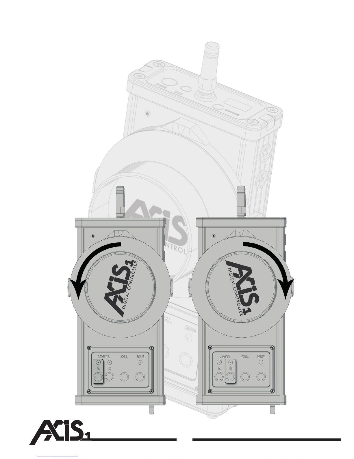
The hand unit has two user denable soft stops that are particularly useful with
long lens or macro work. You can choose a smaller area of the focus range and
‘throw away’ the rest to give you greater resolution and control, as the entire
range of the focus knob is then applied to the selected section. To do this, you
simply turn the knob to the rst stop you want to set, then press and hold the A
or B button. You need to press the button you turn the knob towards, so if you are
turning the knob clockwise, you use the B button, and vise versa. The light will
illuminate green showing the stop has been made. You can set both stops or just
one stop if you like. To erase the stop, you press the button again and the light will
extinguish. Please note the A/B lights are indications that the motor is responding to your changes. The A/B buttons and lights will not function if the receiver
unit is switched o.
18
Soft Stops
Page 21
19
Run/Stop
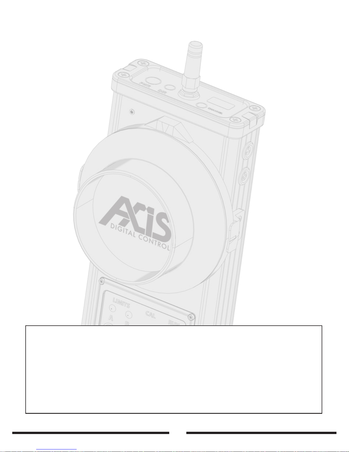
The Axis1 has a ve pin 0B Lemo on the receiver unit to interface with various
cameras to control camera run. The connector is set up to control standard
contact closure systems, such as the Arri RS found on the Alexa/435 etc and we
have also got two dedicated pins to cater for the Red EPIC/Scarlet cameras which
use a non standard camera trigger system. No extra boxes or complicated cables
are required to control the Red cameras. Momentary or latch operation is selected
intelligently by the receiver unit based upon which cable is used. No menu
settings or changes to the Axis1 need to be made to use any camera run, you just
plug the cable in and it will automatically congure itself to work. Please note
that on some cameras you may need to alter settings in the cameras menu to
enable external camera trigger. Please refer to the cameras literature for
information about this.
The Axis1 features two way data transmission, and the receiver unit can report
back to the transmitter to conrm successful receiver tally, this means that the
run button will not do anything unless a receiver is operational. Please note that
as of this time, the receiver does not monitor camera tally. This will be
implemented for some selected cameras in the future. The record light on the
transmitter will only light when it has conrmed that the signal has been received
and the run signal has been sent to the camera. It is always advised to check
camera tally directly with the camera to ensure it is rolling.
Please note that with contact closure systems such as the Arri Alexa, if the camera
is started with the hand unit, and then stopped with the run button on the
camera body, the tally light on the hand unit will be out of sync with the record
status on the camera. To x this, you will need to run the camera from the run
button on the body, and stop it from the hand unit to re synchronise the units.
Running the RED Epic / Scarlet cameras
In the case of the Red EPIC/Scarlet cameras, the Axis1 cable terminates in a BNC
connector. This plugs into the cameras Sync port (Lemo 00) via the Sync port
breakout cable, available from RED. Please use the white BNC. Although it feels
like this cable should plug into the control plug, it needs to plug into the sync for
the camera remote run to work. Some menu changes may need to be made to
the camera to enable the GPIO trigger function. Consult the cameras literature for
information about this.
Run/Stop
Page 22
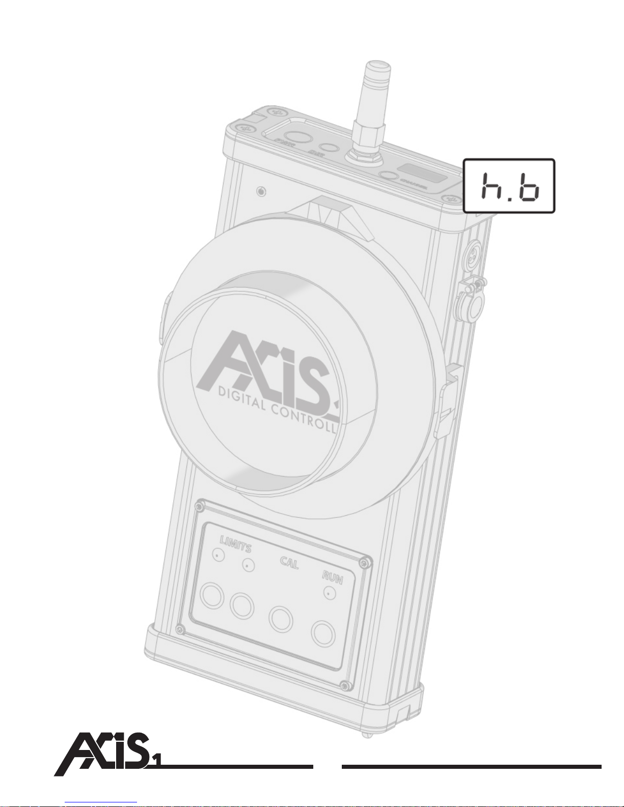
Hand unit
The Axis1 hand unit accepts a Canon LP-E6 style lithium battery. You can use the
Canon batteries or any of the third party equivalents. From a Canon LP-E6 battery,
you can expect around four days of normal shooting use.
When the battery is running low h.b (hand unit battery) will
show on the screen.
Receiver
The receiver runs on 12-36v DC, and this is connected via the 2pin 0B Lemo
connector marked PWR. (pin1 +ve, pin2 –ve).
Current requirements:
Idle – No motor movement: 80-100ma
Normal operation on reasonably sti lens: 600-800ma
Very fast operation on reasonably sti lens: 800-1000ma
(When accelerating fast on stier lenses, a spike of around 1.5-2a may
occur)
Due to the power and electronic design of the motor, the Axis1 focus system may
draw more current than other similar focus devices. Please bear this in mind when
selecting your power source. When moving at speed on a sti lens, the system
can draw up to 5 amps for short periods of a few milliseconds. This is too much for
many camera power outputs, such as the Arri Alexa 12v socket (2amps) and the
Red One output which is 1.75 amps. It is always recommended that the receiver
unit is powered with a Dtap connector straight o the battery, or some other
power supply that has the capability to supply the required current.
20
HAND UNIT
BATTERY LOW
Page 23
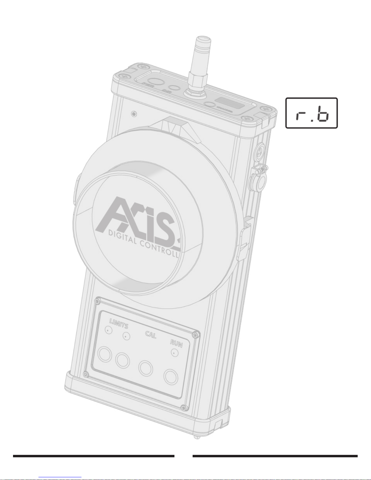
21
Power
Low receiver battery warning
If the power supply powering the receiver unit runs below 10v, then a warning
will show on both the hand unit and the receiver. A ashing orange indicator on
the hand unit, Accompanied by the message r.b (receiver
battery) will show. The unit will still operate at this voltage, but
bear in mind, the motor will run slower. If the Axis1 receiver unit
is powered o the same battery that the camera is running from,
this will serve as a low battery warning for the camera as well. If
The battery is changed, calibrating the motor again will not be
required.
RECEIVER UNIT
BATTERY LOW
Page 24
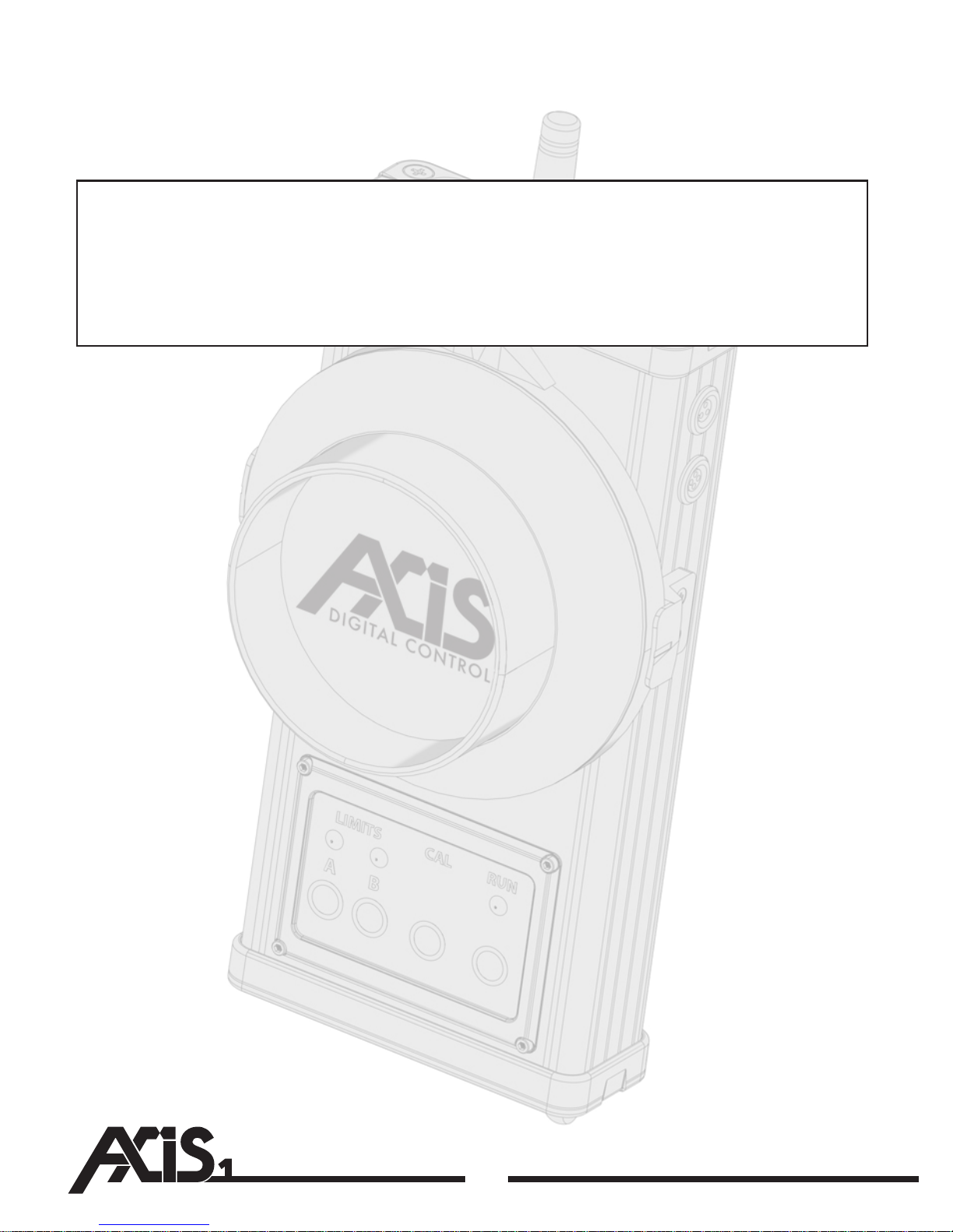
When using modern DSLR lenses that have no physical stop on the focus ring,
auto calibration cannot be used. These lenses must be calibrated manually using
the following steps.
BEFORE STARTING MANUAL CALIBRATION, ENSURE THAT THE MOTOR IS
NOT ENGAGED TO THE LENS GEAR. WHEN IN MANUAL CALIBRATION
MODE, THE MOTOR MOVES AT FULL SPEED AND TORQUE. PLEASE ENSURE
THAT YOU ARE HAPPY AND FAMILIAR WITH THE SPEED BEFORE ENGAGING
THE GEARS TO AVOID UNINTENTIONAL DAMAGE TO THE LENS.
To start manual calibration, press the inf.rot button on the receiver unit and the
indicator light will go red. The receiver and the hand unit will ash U.C for
uncalibrated, and the A and B soft stop buttons will ash, indicating that they
need to be set.
With the teeth away from the lens, turn the knob until it passes its centre point. At
this point, the motor and knob will sync and the knob will now control the motor
position.
The motor in this mode moves very fast and with high torque. Please turn the
knob and motor back and forth a bit to familiarise yourself with the speed and
response. Once you are happy, move the lens to the middle of its range of
rotation and mesh the motor and lens gears together.
Slowly and carefully move the knob towards the ashing A button (Anti
clockwise) until the lens is aligned on its stop. Press and hold the A button to
record the stop. Now move the knob the other way towards the B button
(Clockwise) until you are on the stop. Press and hold the B button to record this
stop.
22
Page 25
23
Innate Rotation Mode
You can now move the knob around inside the calibrated positions.
Please note that innitely rotating DSLR lenses were never built to be focused
repeatedly in this way. Never trust a marked focus ring with DSLR lenses, as the
external focusing ring is not fully attached to the focusing mechanism, repeating
focusing marks is near impossible with these lenses. This is not a fault of the focus
system, but an inherent problem with these types of lenses.
Page 26
24
Compliance
FCC warning statement
This device complies with Part 15 of the FCC Rules.
Operation is subject to the following two conditions:
(1) This device may not cause harmful interference, and
(2) This device must accept any interference received,
including interference that may cause undesired operation.
This equipment complies with FCC radiation exposure limits
set forth for an uncontrolled environment. End users must
follow the specic operating instructions for satisfying RF
exposure compliance. This transmitter must not be
co-located or operating in conjunction with any other
antenna or transmitter.
Changes or modications not expressly approved by the
party responsible for compliance could void the user's
authority to operate the equipment
Trade name: Axis 1
Model Number: Axis 1
FCCID: OUR-XBEEPRO
Page 27
25
Connector Pinouts
Connector Pinouts
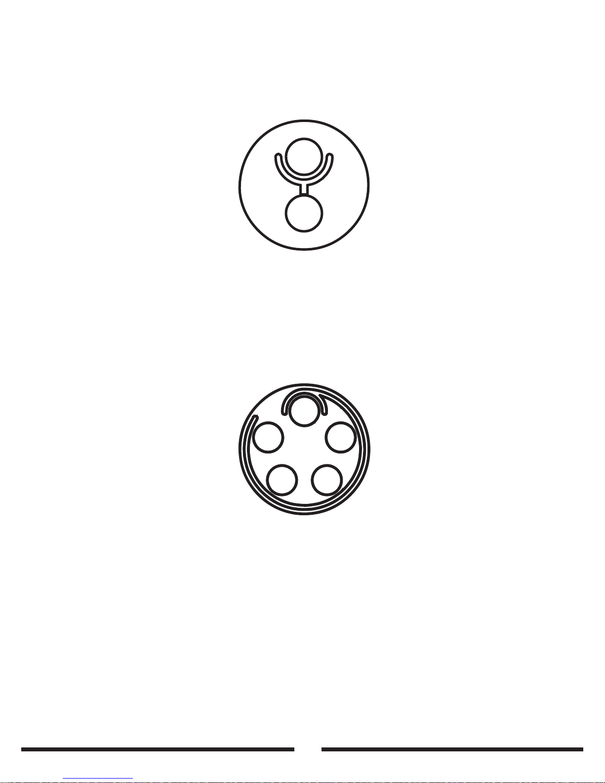
RX Power - 0B 2pin Lemo
Pin 1 - +12v
Pin 2 - GND
Run/stop - 0B 5pin Lemo
Pin 1 - +3.3v output (for RED Epic/Scarlet only)
Pin 2 - GND (for RED Epic/Scarlet only)
Pin 3 - Solid state relay (For contact closure run - use
with pin 4)
Pin 4 - Solid state relay
Pin 5 - ID channel
1
2
1
2
3
4
5
Page 28
L.E.D Display Key
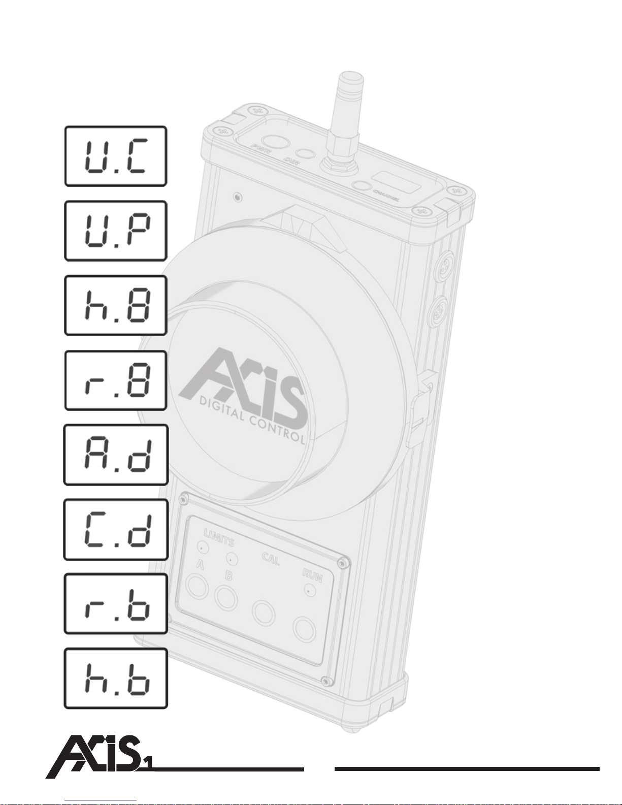
U.C - Uncalibrated
U.P - Unplugged motor
H.0-9 - Strength of signal being received by the hand unit
r.0-9 - Strength of signal being received by the receiver
A.d - Anticlockwise direction selected
C.d - Clockwise direction selected
r.b - Receiver battery low
h.b - Handunit battery low
26
L.E.D Display Key
Page 29

Page 30
 Loading...