

Hochiki America HEC24, HES24, HEH24, HEH12, HEC3-24 Instructions Manual
...
HEC24, HES24, HEH24 & HEH12 SERIES
HEC3-24, HEC3-12, HES3-24 & HES3-12 SERIES
ANSI/UL 1971 and/orANSI/UL 464 COMPLIANT
VISIBLE AND/OR AUDIBLE
ANSI/UL 1638 and/orANSI/UL 464 COMPLIANT
SIGNALING APPLIANCES
I. INTRODUCTION
The Hochiki America models HEC24, HES24, HEH24, HEH12, HEC3-24, HES3-24, HEC3-12, HES3-12, WHEC24, WHES24 are high quality audible and/or visible signaling appliances. The
high intensity strobe utilizes a Xenon flash tube that generates a high-intensity flash visible from all angles. This appliance is intended to provide a visible, audible or audible/visible, depending
on the model, notification signal for the purpose of life safety and property protection. The HEC3-24, HES3-24, HEC3-12, HES3-12 are provided with a slider switch which allows for candela
selection at the installation site; the candela intensities which can be selected are 15Cd, 30Cd, 60Cd, 75Cd, or 110Cd (24VDC only). The HEC24 and HES24 are fixed candela units; the
candela intensities which can be ordered, are 177Cd and 15/75Cd. The WHEC24 and WHES24 are fixed candela units, available in a 75 candela intensity only. This appliance is ideal for any
occupancy that requires notification appliances per the applicable building or fire code or wherever dependable alarms are required.
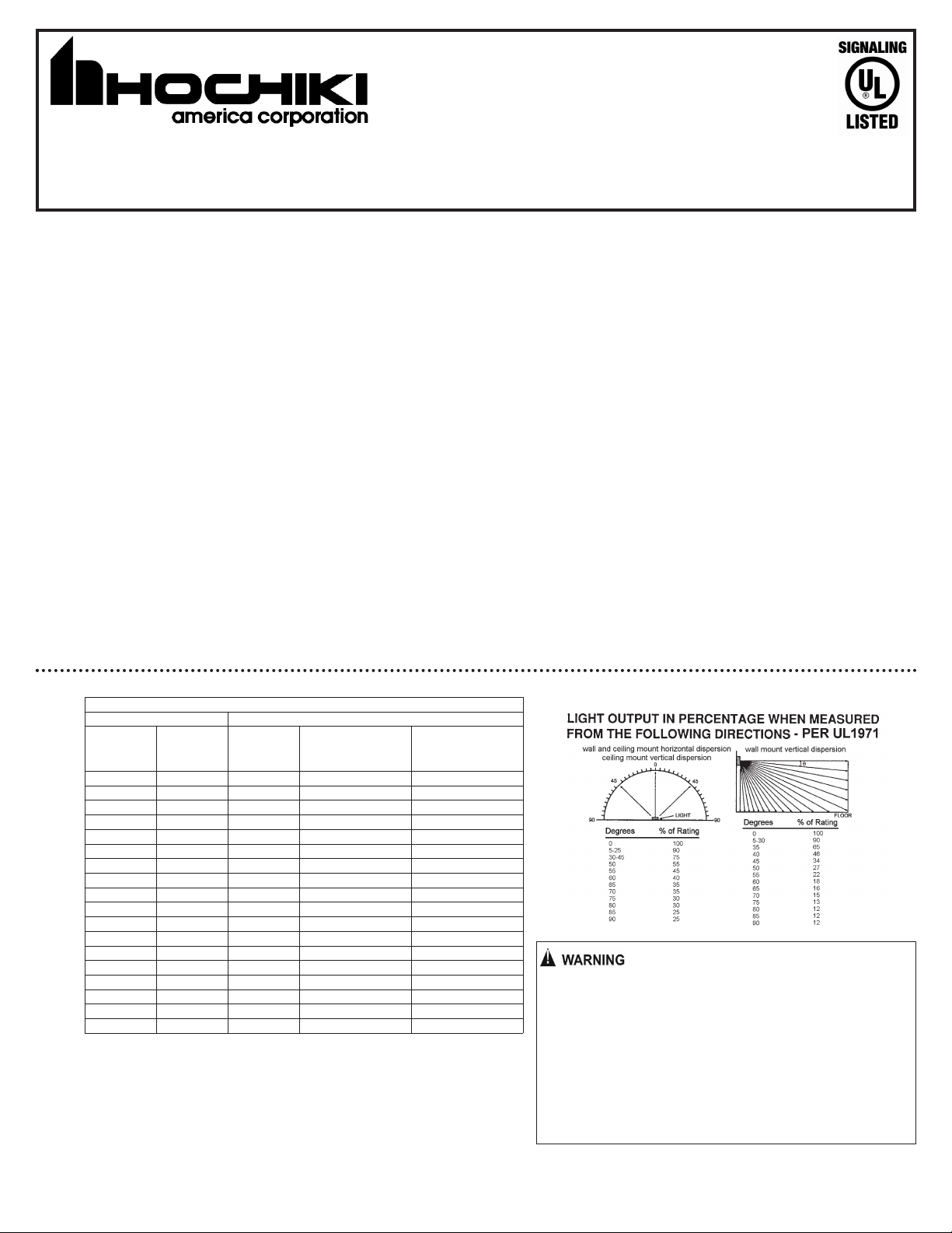
The HEC24, HES24, HEC3-24, HES3-24, HEC3-12, HES3-12 strobe is listed in compliance with ANSI/UL 1971, Signaling Appliances for the Hearing Impaired (The 15/75Cd model on the
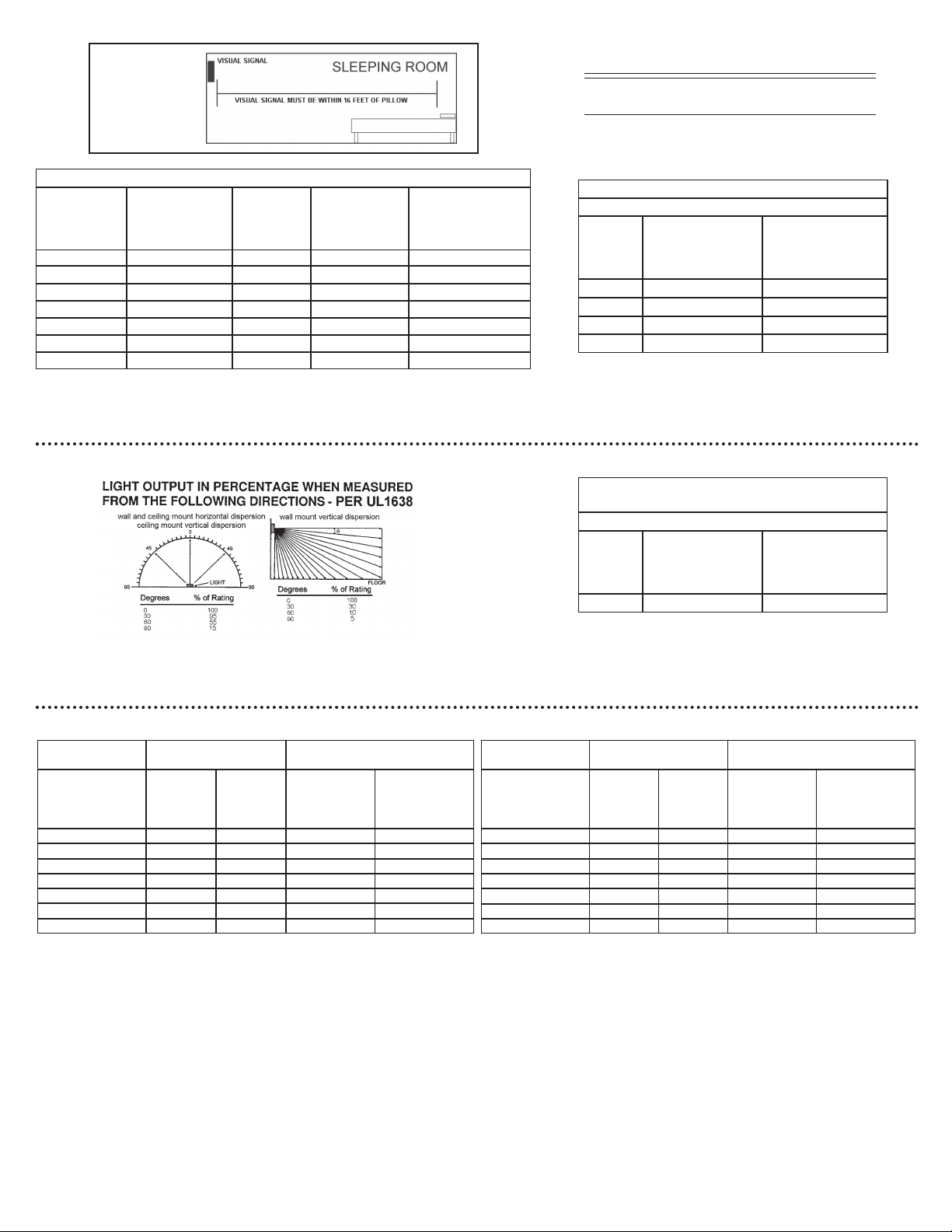
HEC24 and HES24 is additionally listed in compliance with ANSI/UL1638). The WHEC24 and WHES24 strobe is listed in compliance with ANSI/UL 1638, Visual Signaling Appliances - Private
Mode Emergency and General Signaling.
II. LOCATION
This appliance is intended for use in Fire Alarm Systems and is to be installed in accordance with this manual, the recommendation of the local authorities having jurisdiction, and other NFPA
documents that provide standards on notification appliances for protective signaling systems. The HEC24, HES24, HEH24, HEH12, HEC3-24, HES3-24, HEC3-12, HES3-12 are intended for
indoor installations only; this appliance is not listed for outdoor or drip proof applications. The WHEC24 and WHES24 are intended for indoor or outdoor installations; this appliance is rated for
outdoor or drip proof applications when used in conjunction with the HGOE Enclosure.
Wall mounted strobe and horn/strobe appliances shall have their entire lens at heights above the finished floor of not less than 80 in. (2m) and not greater than 96 in. (2.4m)**. Spacing shall be
in accordance with Table A. If a room configuration is not square, the room size that will entirely encompass the room or subdivide the room into multiple squares shall be used. Wall mounted
horn only appliances shall have their tops above the finished floors at heights of not less than 90 in. (2.30m) and below the finished ceilings at heights of not less than 6 in. (152mm). Different
mounting heights shall be permitted by the AHJ provided the sound pressure level requirements of NFPA 72 are met.
III. MOUNTING, ROUGH-IN BOX AND RUN WIRING
This unit is designed for mounting to most single gang boxes, 4" square outlet boxes, 2-gang masonry boxes or non-metallic 2-gang switch boxes. Conduit entrance to boxes should be
selected to insure sufficient wiring clearance.
1. Run a minimum 18 gauge insulated 2 or more conductor cable.
2. Mount a box for each remote signaling appliance. Screw bracket onto box. Insert signal into bracket and slide to the right firmly into the terminal block receptacle. Place housing over
mounted assembly and screw together with single screw at the bottom of the signal. Cover screw with plastic tab.
NOTICE: WIRING SHOULD BE CONNECTED TO MOUNTING BRACKET PRIOR TO MOUNTING SIGNAL. INCOMING POSITIVE POWER LEAD MUST BE BROKEN AND EACH LEAD IS
TO BE INSERTED INTO EACH OF THE TOP TWO TERMINALS. IF TWO POWER RUNS ARE MADE TO THE SIGNAL, ONE FOR THE STROBE AND ONE FOR THE HORN, ONLY ONE OF
THE RUNS MUST HAVE ITS POSITIVE LEAD BROKEN AND PLACED UNDER THE TWO SEPARATE TOP TERMINALS. A BARRIER IS PROVIDED TO PREVENT BOTH LEADS FROM
BEING PLACED UNDER THE SAME TERMINAL.
WHEC24 & WHES24 SERIES
Table A
HEC24/HES24/HEC3-24/HES3-24/HEC3-12/HES3-12 PRODUCT INFORMATION
Room Spacing for Wall-Mounted Visible Appliances per NFPA 72, 2010 Edition
Maximum Room Size Minimum Required Light Output ( Effective Intensity, Cd)
Meters Feet
6.10 x 6.10 20 x 20 15 NA NA
8.53 x 8.53 28 x 28 30 Unknown NA
9.14 x 9.14 30 x 30 34 15 NA
12.2 x 12.2 40 x 40 60 30 15
13.7 x 13.7 45 x 45 75 Unknown 19
15.2 x 15.2 50 x 50 94 60 30
16.5 x 16.5 54 x 54 110 Unknown 30
16.8 x 16.8 55 x 55 115 Unknown 28
18.3 x 18.3 60 x 60 135 95 30
19.2 x 19.2 63 x 63 150 Unknown 37
20.7 x 20.7 68 x 68 177 Unknown 43
21.3 x 21.3 70 x 70 184 95 60
24.4 x 24.4 80 x 80 240 135 60
27.4 x 27.4 90 x 90 304 185 95
30.5 x 30.5 100 x 100 375 240 95
33.5 x 33.5 110 x 110 455 240 135
36.6 x 36.6 120 x 120 540 305 135
39.6 x 39.6 130 x 130 635 375 185
NA = Not allowable
One Light
per Room
Two Lights per
Room (Located on
Opposite Walls)
Four Lights per Room
(One Light per Wall)
furniture or walls block strobe light.
Strobe light can not be seen when objects such as doors,
NOTICE:
THE VISUAL SIGNAL MUST BE IN THE DIRECT VIEWING AREA OF THE
OCCUPANT IN ORDER TO BE SEEN.
VISUAL SIGNALS FOR THE HEARING IMPAIRED ARE ONLY ONE METHOD
OF ALERTING THE HEARING IMPAIRED. VISUAL SIGNALS MAY NOT BE
THE PREFERRED METHOD FOR NOTIFYING ALL HEARING IMPAIRED
INDIVIDUALS.
THE STROBE LIGHT MUST BE SEEN BY THE SLEEPING PERSON. IF THE
PERSON HAS HEAD TURNED OR OTHERWISE UNABLE TO BE ALERTED
BY VISUAL, THE STROBE WILL NOT BE EFFECTIVE.
550-0534
Page 1
CAUTION:
Strobe light must
be installed within
16 feet of the
pillow when used
in a sleeping area.
**Effective Intensity Requirements
for Sleeping Areas
Visible Notification Appliance
Distance from Ceiling to Top of Lens Intensity
greater than or equal to 24" 110cd
less than 24" 177cd
24VDC CLEAR Lens Indoor Strobe Current Ratings
HEC24 and
HES24 Series
Available
Candela
NOTICE: DC VOLTAGE RANGE LIMITS: 16-33V. FWR VOLTAGE RANGE LIMITS: 16-33V. THIS
PRODUCT WAS ONLY TESTED TO THE STATED VOLTAGE RANGE(S); DO NOT APPLY 80% AND 110%
OF THIS RANGE FOR SYSTEM OPERATION.
HEC3-24 and
HES3-24 Series
Available
Candela
Strobe
Candela
15 42 77
15/75 67 113
30 58 102
60 97 161
75 116 225
110 161 256
177 213 341
Regulated
24VDC Max.
Operating
Current(mA)
Regulated
24VFWR Max.
Operating
Current (mA)
WHEC24 AND WHES24 PRODUCT INFORMATION
12VDC CLEAR Lens Strobe Current Ratings
Use with HEC3-12 and HES3-12 Products
Regulated
Candela
15 92 145
30 141 224
60 260 459
75 312 460
NOTICE: DC VOLTAGE RANGE LIMITS: 8-17.5V. THIS
PRODUCT WAS ONLY TESTED TO THE STATED VOLTAGE
RANGE(S); DO NOT APPLY 80% AND 110% OF THIS RANGE
FOR SYSTEM OPERATION.
Candela
75 170 263
NOTICE: DC VOLTAGE RANGE LIMITS: 16-33V. FWR VOLTAGE
RANGE LIMITS: 16-33V. THIS PRODUCT WAS ONLY TESTED
TO THE STATED VOLTAGE RANGE(S); DO NOT APPLY 80%
AND 110% OF THIS RANGE FOR SYSTEM OPERATION.
12VDC Max.
Operating
Current (mA)
24VDC CLEAR Lens Outdoor
Strobe Current Ratings
Use with WHEC24 and WHES24 Products
Regulated 24VDC
Max. Operating
Current (mA)
Regulated
12VFWR Max.
Operating
Current (mA)
Regulated
24VFWR Max.
Operating
Current (mA)
HORN DECIBEL AND CURRENT RATINGS PRODUCT INFORMATION
Horn Decibel Levels
Minimum SPL
Horn Mode
Temp 3 2400Hz 78 dBA 71* dBA 28 48
Temp 3 Mechanical 76 dBA 70* dBA 25 44
Temp 3 Chime 70* dBA 66* dBA 15 30
Continuous 2400Hz 81 dBA 74* dBA 28 48
Continuous Mechanical 80 dBA 72* dBA 25 44
Continuous Chime 70* dBA 66* dBA 15 30
Whoop 82 dBA 69* dBA 56 62
NOTICE:
THE THREE PULSE TEMPORAL PATTERN IS TO BE USED FOR EVACUATION USE ONLY.
THE SOUND OUTPUT FOR THE TEMPORAL 3 TONE IS RATED LOWER SINCE THE TIME THE HORN IS OFF IS AVERAGED INTO THE SOUND OUT PUT RATING. WHILE THE HORN
IS PRODUCING A TONE IN THE TEMPORAL 3 MODE ITS SOUND PRESSURE IS THE SAME AS THE CONTINUOUS MODE. UNITS HAVE BEEN TESTED TO 0°C, 49°C AND 93%
HUMIDITY.
* Operating the horn in this mode at this voltage will result in not meeting the minimum ANSI/UL 464 sound level required for public mode fire protection service. These settings are acceptable
only for private mode fire alarm signaling use. Use the high dBA setting for public mode applications (the chime tone is always private mode).
at 10Ft. Per
ANSI/UL 464
(HIGH)
Minimum SPL
at 10Ft. Per
ANSI/UL 464
(LOW)
Horn Current Ratings Over
Input Voltage Range of 16-33V
Regulated 24VDC
Max. Operating
Current (mA)
HIGH Setting
Regulated 24VFWR
Max. Operating
Current (mA)
HIGH Setting
Horn Decibel Levels
Minimum SPL
Horn Mode
Temp 3 2400Hz 76 dBA 69* dBA 29 48
Temp 3 Mechanical 75 dBA 68* dBA 26 45
Temp 3 Chime 62* dBA 60* dBA 13 24
Continuous 2400Hz 79 dBA 74* dBA 29 48
Continuous Mechanical 78 dBA 72* dBA 26 45
Continuous Chime 63* dBA 61* dBA 13 24
Whoop 78 dBA 71* dBA 55 61
at 10Ft. Per
ANSI/UL 464
(HIGH)
Minimum SPL
at 10Ft. Per
ANSI/UL 464
(LOW)
Horn Current Ratings Over
Input Voltage Range of 8-17.5V
Regulated 12VDC
Max. Operating
Current (mA)
HIGH Setting
Regulated 12VFWR
Max. Operating
Current (mA)
HIGH Setting
550-0534
Page 2
 Loading...