

Page 1
HOCHIKI YBO-R/SCI & YBO-R/SCIM SHORT CIRCUIT
Base Isolator
Ordering codes
YBO-R/SCI *
1
YBO-R/SCIM (Marine-Approved)
Protocols
ESP/HRE#
Operating Voltage
19-41 Vdc (24 Vdc nominal)
Standby current
60 µA
Current drawn by isolator during fault condition
< 10 mA
Maximum current consumption from remote LED
N/A
Maximum continuous current
1 A
Maximum quantity per loop
127*2
LED colour
Yellow
Ambient temperature range
-10 C to +50 C
Relative humidity
10% to 95% RH (at 40C)
Colour and case material
Ivory or White ABS
Fixing centres
48 mm through to 74 mm
Maximum wire thickness
2.5 mm²/terminal
Weight
92g
Optional cover for stand alone use
SI/CAP
Sensor Type
Ordering Code
Photoelectric sensor
ALG-E, ALG-EN, ALK-E (and all variants)
Ionisation sensor
AIE-E (and all variants)
Temperature sensor
ATG-E, ACB-E, ACB-EW (and all variants)
Multi-Sensor
ACA-E
ISOLATOR BASES & CHQ-SCI/DIN SHORT CIRCUIT
ISOLATOR MODULE
INSTALLATION INSTRUCTIONS
General Description
These devices detect and isolate short-circuits on the loop. When a short-circuit is detected during power up these
isolators will illuminate their integral LED (yellow) and drop the power to the rest of the loop.
YBO-R/SCI & YBO-R/SCIM Isolator Base
The YBO-R/SCI (and the marine-approved equivalent YBO-R/SCIM) is a short-circuit isolator combined in a base
compatible with the ESP range of sensors (see compatibility chart below). The Isolator can also be used as a stand
alone unit with the addition of a simple clip on cover (SI/CAP), in either configuration the unit does not require a loop
address. A remote fire LED facility is provided when a sensor is attached to the base.
Note:- If a sensor is fitted this will still be powered when the device is isolating (yellow LED illuminated).
Specifications
NOTE: See AP0127 for short-circuit isolator specifications
#
The YBO-R/SCI can be used on the HRE protocol as a replacement for the SCI/2a, but as a stand alone isolator only, in other words, with
no sensor fitted.
*1 Fire alarm control panel compatibility is required for this product.
*2 Check with Fire alarm control panel manufacturer for maximum loop quantities
Compatibility
The YBO-R/SCI base isolator has been designed to work with the sensors listed below. All sensors are compatible
with Hochiki ESP (Enhanced System Protocol).
2-3-0-367/ISS6/OCT13
Page 2
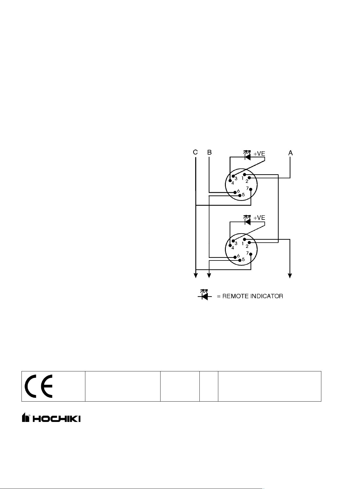
Wiring
The wiring of the YBO-R/SCI & YBO-R/SCIM short
circuit isolator bases should be made as shown right:
A: Loop (+)
B: Loop (-)
C: Cable Screen
Note:- The Remote Indicator will only indicate a fire
condition, but not when the base is isolating.
YBO-R/SCI
0832-CPD-0963
09
EN54-17 Short Circuit Isolators
Hochiki Europe (UK) Ltd
Grosvenor Road, Gillingham Business Park,
Gillingham, Kent, ME8 0SA, England Telephone:
+44(0)1634 260133 Facsimile: +44(0)1634 260132
Email: sales@hochikieurope.com
Web: www.hochikieurope.com
Hochiki Europe (UK) Ltd. reserves the right to alter the
specification of its products from time to time without notice.
Although every effort has been made to ensure the accuracy of
the information contained within this document it is not warranted
or represented by Hochiki Europe (UK) Ltd. to be a complete and
up-to-date description. Please check our web site for the latest
version of this document.
Precautions
Ensure that both devices are installed in accordance with local standards or regulations.
Only install in suitable environments, the following should be avoided : -
Excessive ambient temperature.
Where excessive condensation or moisture is present.
Hazardous areas.
Do not use a high voltage tester on these devices.
Ensure that the YBO-R/SCI & YBO-R/SCIM base isolators are securely fixed to the ceiling or other suitable
surface.
Ensure that the terminals on both devices are securely fastened.
When fitting the YBO-R/SCI & YBO-R/SCIM isolator bases, for proper wiring supervision ensure that the cables
are routed through the base terminals and not spurred off a main wiring route.
Ensure the YBO-R/SCI & YBO-R/SCIM base isolators are fitted with either a sensor or a cover (on HRE
systems only cover may be fitted)
Ensure yellow isolating LED on either device is easily visible.
Protocol specified in TI/006
2-3-0-367/ISS6/OCT13
 Loading...