

Page 1
1
2-3-0-745/ISS4/JULY13
HOCHIKI YBO-BSB BASE SOUNDER BEACON
INSTALLATION INSTRUCTIONS
Products Covered: YBO-BSB installed with ALG-E, ALG-E(NP), AIE-E, AIE-E(NP), ATG-E, ATGE(NP), ACA-E, ACB-E Sensors, CHQ-AB Range of Beacons, CHQ-ARI Remote Indicator and YBNR/3 Standard Base, YBO-R/SCI Short-Circuit Isolator Base (from batch code 6044 only).
Common Configurations
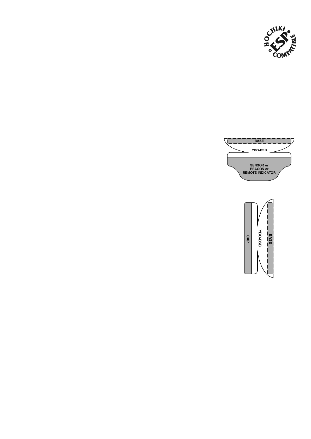
The YBO-BSB can be used in conjunction with an ESP Sensor, Beacon or Remote
Indicator (see Fig.1) or with the addition of a Cap (see Fig. 2).
Address Setting
The default address of the YBO-BSB is 254, and therefore if the YBO-BSB is to be
used as a base sounder (sensor on top) then the address will not need to be changed,
as the control panel will automatically address the sounder as described below.
However, if the sounder is to be used as a wall sounder then the YB O-BSB will need to
be manually addressed from 1 to 127 as described below. Note: Control Panel
compatibility needs to be checked to verify if automatic addressing above 127 is
supported.
Automatic Addressing (Control Panel)
The control panel automatically assigns the address to the base sounder at
initialisation, the address is calculated by taking the address of the sensor that is fitted
to the base sounder and adding 127, this is then stored within the base sounder. For
example, if a sensor is set at address 10 then the base sounder would be automatically
set at address 137. Addresses above 127 may not be visible to the user depending
upon the implementation by the Control Panel.
Manual Addressing (Hand Held Programmer)
Fig. 1
Fig. 2
Introduction
The Loop-Powered Base Sounder Beacon (YBO-BSB) is designed to complement the standard common mounting base
(YBN-R/3) and the isolator base (YBO-R/SCI) in locations where Loop-Powered Sounders and Beacons are required.
The YBO-BSB has connections for both of these types of base as well as for the standard range of Hochiki Analogue
Addressable Sensors and Beacons. The YBO-BSB is designed to give audible and visual alerts in locations such as Hotel
Bedrooms, Offices and Corridors. Note that the YBO-BSB is for indoor use only (Type A) and is rated at IP21.
The beacon contained within this product is a secondary function and therefore must not be used as a visual alarm device
to comply with EN54-23.
The base sounder address can be set using the Hand Held programmer (TCH-B100) from 1 to 254. See the TCH-B100
instructions for further details of address setting. If the YBO-BSB is to be used as a wall sounder then the address should
be set from 1 to 127 before being installed. If the YBO-BSB is to be used as a base sounder (sensor on top) then the
address should be set from 128 to 254.
Precautions
Ensure that the base sounder is installed in accordance with Local Standards or Regulations.
Check that both sensor and mounting base are compatible with the YBO-BSB.
Only install in suitable environments, the following in particular should be avoided: -
A high voltage tester must not be used with this base sounder.
Ensure that the base sounder is securely fixed to the mounting base.
For proper wiring supervision ensure that the cables are wired as shown in the diagram below.
Excessive ambient temperature.
Where excessive condensation or moisture is present.
Hazardous areas.
Page 2
2
2-3-0-745/ISS4/JULY13
FIG. 4
Table 1
Locking Mechanism
The base sounder can be locked onto the relevant
mounting base by removing a plastic lug on the
underside of the sounder (see Fig. 3).
The sounder can then only be removed by using a
special Removal Tool (TSC-SRT), which is available
from Hochiki Europe (UK) Ltd.
Nominal Sound Output dB(A)*1 *2
Current Drawn mA*3
50
0.8 55
0.8 60
0.8 70
0.8 78
1.5 80
2.0 85
3.0
88
4.5
90
6.5 93
8.0 94
10 95
11
98
16
*1 @ 1m distance
*2 Refer to AP092 (available from our website) for complete EN54- Aweighted sound levels
*3 An additional 5mA will be drawn when beacon is activated
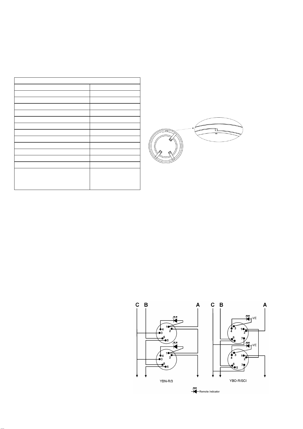
Wiring
Please refer to Fig. 4 for wiring the Standard
Mounting Base (YBN-R/3) and the Short-Circuit
Isolator Mounting Base (YBO-R/SCI):
A: Loop (+)
B: Loop (-)
C: Cable Screen (where used)
Operating Voltage: 17
NOTE: See AP0127 for short-circuit isolator
specifications for YBO-R/SCI
Fig. 3
Remove tab carefully using a pair
Tones and Volumes
Table 1 below shows the full range of sound outputs available from the YBO-BSB and the amount of current drawn when
operated. When the YBO-BSB is selected to be a base sounder (sensor on top) the default sound output will be 85dB(A).
The YBO-BSB is also capable of utilising a number of different EN54-3 Approved tones. A total of 51 tones are available,
these are listed in Table 2 and in document AP092 available from our web site. The tone of the sounder and the
volume level is selected and controlled by the control panel, therefore check with the control panel manufacturer
for options and default values available.
Installation
The base sounder is designed to be mounted on the Standard Mounting Base (YBN-R/3) or the Short-Circuit Isolator
Mounting Base (YBO-R/SCI, from batch code 6044 only) in the same method as a Sensor. The terminals on the mounting
base hold the YBO-BSB and in turn the terminals on the YBO-BSB hold the sensor, beacon or cap if being used as a wall
sounder (see below). For correct wiring of the appropriate mounting base, please refer to the diagram below.
Using the YBO-BSB as a Wall Sounder Beacon
A push-fit cap (SI/CAP) is available to cover the electrical connections if an analogue sensor, beacon or indicator is not
being fitted (see Fig. 2). Align the arrow marked inside the cap with the sensor alignment mark on the base sounder. This
will ensure the four tabs on the cover will engage with the matching slots in the base sounder. Push cap firmly onto the
base sounder until it clicks into place.
Page 3

3
2-3-0-745/ISS4/JULY13
Table 2
Tone
Number
Tone
Description
Graphic
Representation
Tone
Number
Tone
Description
Graphic
Representation
0
Sounder Off
19
800 Hz : 250 ms
970 Hz : 250 ms
1
925 Hz : 250 ms
628 Hz : 250 ms
20
2850 Hz Continuous
2
925 Hz Continuous
21
2400 Hz : 250 ms
2850 Hz : 250 ms
3
628 Hz Continuous
22
800 Hz : 500 ms
970 Hz : 500 ms
4
(French)
554 Hz : 100 ms
440 Hz : 400 ms
23
2850 Hz : 500 ms
Off : 500 ms
5
(Swedish)
660 Hz : 150 ms
Off : 150 ms
24
925 Hz : 250 ms
Off : 1000 ms
6
925 Hz : 150 ms
Off : 600 ms
25
970 Hz Continuous
7
670 Hz : 250 ms
845 Hz : 370 ms
26
660 Hz : 1800 ms
Off: 1800 ms
8
Whoop
500 Hz - 1200 Hz 3000 ms
Off : 500 ms
27
660 Hz : 6500 ms
Off : 13000 ms
9
1200 Hz : 500 ms
500 Hz : 500 ms
28
660 Hz Continuous
10
970 Hz : 500 ms
Off : 500 ms
29
554 Hz : 500 ms
440 Hz : 500 ms
11
Sweep
800 Hz - 970 Hz
over 140 ms (7 Hz)
30
660 Hz : 500 ms
Off : 500 ms
12
Sweep
800 Hz - 970 Hz
over 1000 ms (1 Hz)
31
2850 Hz : 150 ms
Off : 100 ms
13
Sweep
800 Hz - 970 Hz
over 20 ms (50 Hz)
32
Sweep
2400 Hz – 2850 Hz
over 20 ms (50 Hz)
14
Sweep
2400 Hz – 2850 Hz
over 140 ms (7 Hz)
33
Sweep
800 Hz – 970 Hz
over 500 ms (2 Hz)
15
Sweep
2400 Hz – 2850 Hz
over 1000 ms (1 Hz)
34
988 Hz : 250 ms
645 Hz : 250 ms
16
Sweep
300 Hz – 1200 Hz
over 1000 ms (1 Hz)
35
510 Hz : 250 ms
610 Hz : 250 ms
17
ISO8201 : 970 Hz : 500 ms
36
Sweep
800 Hz – 970 Hz
over 110 ms (9 Hz)
18
ISO8201 : 2850 Hz : 500
ms
37
Sweep
800 Hz – 970 Hz
over 330 ms (3 Hz)
Page 4

4
2-3-0-745/ISS4/JULY13
Tone
Number
Tone
Description
Graphic
Representation
Tone
Number
Tone
Description
Graphic
Representation
38
845 Hz Continuous
46
440 Hz : 600 ms
Off : 600 ms
39
970 Hz : 1000 ms
Off : 1000 ms
47
Whoop
500 Hz – 1200 Hz : 3750 ms
Off : 250 ms
40
800 Hz : 150 ms
970 Hz : 150 ms
48
ISO8201
925 Hz, 628 Hz : 250 ms
Off 500 ms
41
Sweep
2400 Hz – 2850 Hz
over 110 ms (9 Hz)
49
ISO8201 : Sweep
300 Hz – 1200 Hz : 500 ms
Off : 500 ms
42
Sweep
2400 Hz – 2850 Hz
over 330 ms (3 Hz)
50
ISO8201 : Sweep
1200 Hz – 300 Hz : 500 ms
Off : 500 ms
43
2850 Hz : 1000 ms
Off : 1000 ms
51
Whoop
500-1200 3.5s/0.5s
44
2400 Hz : 150 ms
2850 Hz : 150 ms
45
(German) Whoop
1200 Hz – 500 Hz :
1000ms
Off : 10 ms
Protocol specified in TI/006
YBO-BSB
0832-CPD-0490
06
EN54-3:2001 Sounders
Hochiki Europe (UK) Ltd
Grosvenor Road, Gillingham Business Park,
Gillingham, Kent, ME8 0SA, England Telephone:
+44(0)1634 260133 Facsimile: +44(0)1634 260132
Email: sales@hochikieurope.com
Web: www.hochikieurope.com
Hochiki Europe (UK) Ltd. reserves the right to alter the
specification of its products from time to time without notice.
Although every effort has been made to ensure the accuracy of
the information contained within this document it is not warranted
or represented by Hochiki Europe (UK) Ltd. to be a complete and
up-to-date description. Please check our web site for the latest
version of this document.
 Loading...