

Page 1
HOCHIKI YBO-BS BASE SOUNDER
INSTALLATION INSTRUCTIONS
Products Covered: YBO-BS installed with ALG-E, ALG-E(NP), AIE-E, AIE-E(NP), ATG-E,
ATG-E(NP) , ACA-E, ACB-E Sensors, CHQ- AB Rang e of Beacons, CHQ-ARI Remote In dicator an d
YBN-R/3 Standard Base, YBO - R/SCI Short-Circuit Isol at or Base (from bat ch code 6044 only).
Introduction
The Loop-Powered Sounder Base (YBO - B S ) is designed to complement the standard common mounting base
(YBN-R/3) and the isolator base (YB O-R/SCI) in locat ions where Loop-Powered Sounders are required. The YBOBS has connections for both of these types of base as well as for the standard range of Hochik i Analogue
Addressable Sensors and Beacons. The YBO- B S is designed to give audi bility in locations such as Hotel
Bedrooms, O ff ices and Corridor s. Note that the Y B O-BS is for indoor use onl y ( Type A) and is rat ed at IP21.
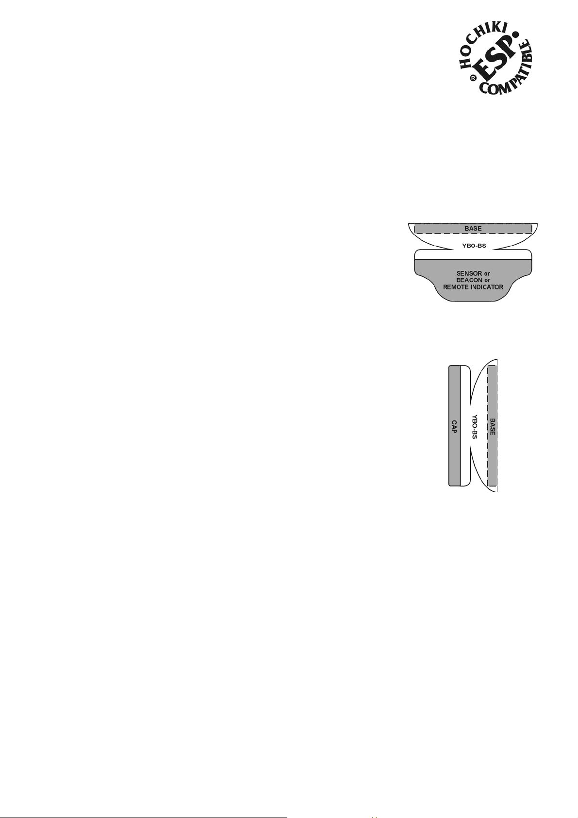
Common Configurations
The YBO-BS can be used in conjunction with an ESP Sensor, Beacon or Remote
Indicator (see Fig.1) or with the addit ion of a Cap ( see Fig. 2).
Address Setting
The default address of the Y BO-BS i s 254, and therefore if the YBO-BS is to be
used as a base sounder (sensor on top) then the address will not need to be
changed, as the control panel will automatically address the sounder as described
below. However, if the sounder is to be used as a wall sounder then the YB O-BS
will need to be manually addressed f r om 1 to 127 as described below. Note:
Control Panel compatibility needs to be checked to verify if automatic
addressin g above 127 is supported.
Fig. 1
Automatic Addressing (Control Panel)
The control panel automatically assigns the address to the base sounder at
initiali sation, the address is calculated by taking the addr ess of the sensor that is
fitted to the base sounder and adding 127, this is t hen stor ed within the base
sounder. For ex ample, if a sensor is set at addr ess 10 then the base sounder
would be automat icall y set at address 137. Addresses above 127 may not be
visible to the user depending upon the i mplementation by the Control Panel.
Fig. 2
Manual Addressing (Hand Held Programmer)
The base sounder address can be set using the Hand Held programmer (TCH-B100) from 1 t o 254. See the TCHB100 instruct ions for further details of address setting. I f the YBO-BS is t o be used as a wall sounder then the
address should be set from 1 to 127 before being instal led. If the YBO -BS is to be used as a base sounder
(sensor on top) then the address should be set f rom 128 to 254.
Precautions
Ensure that the base sounder is installed i n ac c or danc e with Local St andards or Regulations.
Check that bot h sensor and m ounting base are com patible with the YBO- B S .
Only i nst all in suitable envir onments, the following in part icular shoul d be avoided: -
Excessive ambient temperature.
Wher e excessive condensation or moisture is present.
Hazardous areas.
A high voltage tester must not be used wit h this base sounder.
Ensure that the base sounder is securely fixed to the mounti ng base.
For proper wiring supervision ensure that t he c ables are wired as shown in the diagram below.
2-3-0-629/ISS3/JUN11
Page 2
Tones and Volumes
Table 1 below shows the ful l range of sound outputs available from the YBO-BS and the amount of current drawn
when operated. When the YBO-BS is select ed to be a base sounder (sensor on top) the default sound output will
be 85dB(A). T he Y B O-BS is al so capable of ut ilising a number of different EN54-3 Approved tones; these are
listed I n Table 2. T he tone of the sounder and the volume level is selected and co ntroll ed by the co ntrol
panel, therefore ch eck with the contro l panel man ufacturer for opti ons and default values availab le.
Table 1
Nominal Sound O utput dB(A)*‡ Current Drawn mA
50 0.8
55 0.8
60 0.8
70 0.8
78 1.5
80 2.0
85 3.0
88 4.5 18 (2850:ISO8201) 2850Hz/0.5s, 0Hz/0.5s
90 6.5
93 8.0
94 10
95 11
98 16
Tone Number Tone Frequencies & Durations*
1 925Hz/0.25s, 628Hz/0.25s
4 (French) 554Hz/0.1s, 440Hz/0.4s
5 (Swedish) 660Hz/0.15s, 0Hz/0.15s
8 (Whoop) 500HZ/3s, 1200Hz/0.5s
12 (Sweep) 800Hz/1s, 970Hz/0s
15 (Sweep) 2400Hz/1s, 2850Hz/0s
17 (970:ISO8201) 970Hz/0.5s, 0Hz/0.5s
* Refer to AP083 (available from our website) for complete EN54-3 A-weighted
sound levels.
‡
@ 1m distance.
Table 2
Installation
The base sounder is designed to be mounted on the Standard M ounting Base (YBN-R/3) or the Short-Circuit
Isolator Mounting Base (YBO - R/SCI, from batch code 6044 only) in the same method as a Sensor. The t er minals
on the mounting base hold the YBO-BS and in turn the terminals on the YBO-BS hold the sensor, beacon or cap if
being used as a wall sounder (see below). For c or r ec t wiring of the appropriate mounting base, please refer to t he
diagram below.
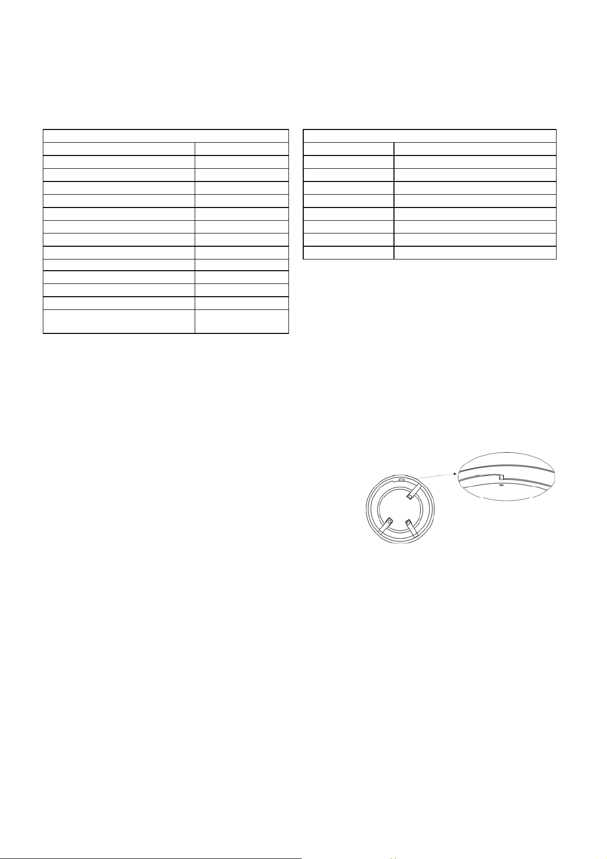
Locking Mechanism
Remove tab carefully using a pair of pliers.
The base sounder can be locked onto the relevant mounting base
by removing a plastic lug on the underside of the sounder (see
Fig. 3) .
The sounder can then only be r emoved by using a special
Removal Tool (TSC-S RT), which i s available from Hochiki
Europe (UK) Ltd.
Fig. 3
Using the YBO-BS as a Wall Sounder
A push-fi t cap (SI/ CA P ) is available to cover the elec trical connecti ons i f an analogue sensor, beacon or indicat or
is not being fitted (see Fig. 2) . Ali gn the arrow marked inside the cap wit h the sensor alignm ent mark on the base
sounder. This will ensure the four tabs on the cover will engage with the matchi ng slots in the base sounder. Push
cap fi r mly onto the base sounder until it clicks into place.
2-3-0-629/ISS3/JUN11
Page 3

Wiring
Please ref er to the following
diagrams for wiri ng the Standard
Mounting Base (YB N- R/3) and the
Short-Circuit I solator Mounting Base
(YBO-R/SCI):
A: Loop (+)
B: Loop (-)
C: Cable Screen (where used)
Operating Vol t age: 17 ~ 41 Vd.c.
Protocol specified in TI/006
YBO-BS 0832-CPD-0374 06 EN54-3:2001 Sounders
Hochiki Europe (UK) Ltd
Grosvenor Road, Gillingham Business Park,
Gillingham, Kent, ME8 0SA, England Telephone:
+44(0)1634 260133 Facsimile: +44(0)1634 260132
Email: sales@hochikieurope.com
Web: www.hochikieurope.com
Hochiki Europe (UK) Ltd. reserves the right to alter the
specification of its products from time to time without notice.
Although every effort has been made to ensure the accuracy of
the information contained within this document it is not warranted
or represented by Hochiki Europe (UK) Ltd. to be a complete and
up-to-date description. Please check our web site for the latest
version of this document.
2-3-0-629/ISS3/JUN11
 Loading...