

Page 1

2-3-0-237/ISS5/SEP15
HOCHIKI TCH-B200 – ESP DEVICE PROGRAMMER
OPERATING INSTRUCTIONS
General Description
The TCH-B200 ESP Programmer is designed for use with the following products:
ALK / ALG-ALNC
Analogue Photoelectric
Sensors
AIE-EC
Analogue Ionisation Sensor
ATG-EC
Analogue Heat Sensor
CHQ-WS2C
Wall Sounder
ATJ / ACB-EC / ACB-EW2
Analogue Multi-Heat Sensors
CHQ-WSB/WSB2C
Wall Sounder Beacons
ACC / ACA-EC
Analogue Multi-Sensors
YBO-BSC
Base Sounder
YBO-BSB/BSB2C
Base Sounder Beacons
HCP Range3
Analogue Manual Call Points
CHQ-CB/WB/ABC
Addressable Beacons
CHQ-POM3
Powered Output Module
CHQ-SIM3
Single Input Module
CHQ-ARIC
Addressable Remote Indicator
C = device clips straight onto Programmer, 2 = in conjunction with PL-2 Programming Lead, 3 = in conjunction with PL-3 Programming
Lead
The programmer is used to set the address of the above products for use with Hochiki ESP systems. The unit is
designed to be light, robust and easy to use and operates from a single PP3 size, heavy-duty battery which gives
the capacity for up to 8,000 operations.
Keys
The TCH-B200 has 3 operating keys, a middle blue key and lower left and right grey keys, these keys have the
following functions.
Left (grey key) key - Power On - automatically reads the address of the fitted sensor - subsequent
operations of this key will advance the programmer address in units of 10.
Right (grey key) key - Advances the programmer address display in units of 1. Also used as the Power Off
button.
Centre (Blue key) key - Stores the displayed address to the Sensor and is used to read the Sensor’s
analogue levels.
Operation - Address Setting
Locate the Device onto the programmer ensuring the 3 locating pips line up with the grooves in the
programmer.
Press the left (grey) key to switch the programmer on, a battery check message will be displayed followed by
the address of the device fitted (previously un-programmed devices will read 127).
Select the required address by incrementing the programmer display (left grey key, 10’s, right grey key,
units). Whilst the display is showing an address different to that stored in the device, 3 dots will also flash.
Once the wanted address is displayed press the centre (blue) key to store the address in the device. Once
the address is correctly stored the 3 dots will cease to flash and the display will show the address set.
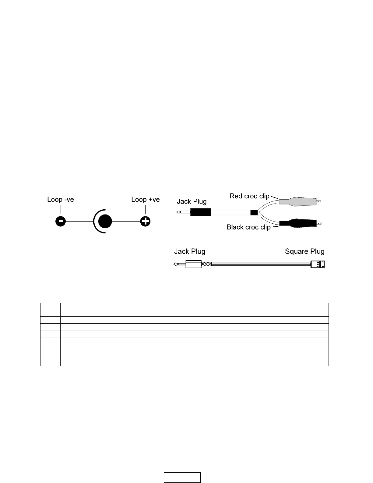
To program a CHQ-BS a PL-2 Programming Lead must be used, firstly connect the plug into the remote
(Blue)
www.acornfiresecurity.com
www.acornfiresecurity.com
Page 2
2-3-0-237/ISS5/SEP15
programming socket on the TCH-B200 and then connect the black croc clip to the C terminal, and the red
croc clip to the L terminal on the base sounder. The address can now be programmed as described above.
To program a CHQ-SIM, CHQ-POM, CHQ-WS or any HCP Manual Call Point a PL-3 Programming Lead
must be used, firstly connect the plug into the remote programming socket on the TCH-B200 and then
connect the square plug into the programming socket on the device. The address can now be programmed
as described above.
Please note that when programming CHQ-BS, CHQ-WS, CHQ-WS2 or the CHQ-WSB the maximum
address permissible is 254. Individual device and Control Panel instructions should be checked for
address range.
Operation - Analogue Level Reading
If the device is an AIC-E / AIE-E then the analogue reading should be ignored for the first 30 seconds until the
device stabilises.
To read the analogue level of a sensor:
Locate the sensor on the programmer and switch on as described in the previous section.
Press the centre (blue) key, an ‘A’ (for analogue value) will be displayed followed by the analogue value of
the Sensor which will be constantly updated for up to 3 minutes or until the right (grey) key is pressed to
switch the unit off.
Remote Programming Socket and Programming Leads
The remote programming socket allows the user to program other ESP devices that contain the EEPROM
technology utilising a Programming Lead.
Programming Socket
PL-2 Programming Lead
Caution
Only to be used with the ESP Programmer
and Hochiki loop devices.
Do not short croc clips together.
Remove from programmer when not in use.
PL-3 Programming Lead
Ancillary Functions
In addition to the main functions the TCH-B200 may display the following messages:
bAt
If displayed on subsequent power on, a low battery voltage should be suspected - this facility will
operate with sufficient life in the battery for approximately 3000 address setting operations left.
E0
Attempting to program an address greater than 127
E1
Attempting to program an address with no Sensor connected
E2
Cannot find Sensor on power on
E3
Non valid response from ASX sensor
E4
Cannot find a device to program
E5
Device read error
E6
Fail during analogue level reading
Hochiki Europe (UK) Ltd. reserves the right to
alter the specification of its products from time
to time without notice. Although every effort has
been made to ensure the accuracy of the
information contained within this document it is
not warranted or represented by Hochiki Europe
(UK) Ltd. to be a complete and up-to-date
description. Please check our web site for the
latest version of this document.
www.acornfiresecurity.com
www.acornfiresecurity.com
Page 3

2-3-0-237/ISS5/SEP15
HOCHIKI TCH-B200 – BETRIEBSANLEITUNG FÜR DEN
ESP-PROGRAMMIERER
Allgemeine Beschreibung
Der TCH-B200 ESP-Programmierer ist für die Verwendung mit folgenden Produkten geeignet:
ALG-E / ALG-ENC
Analoger photoelektrischer Sensor
CHQ-BS2
Schallgeber
AIE-EC
Analoger Ionisationssensor
CHQ-WSC
Wandmontierter Schallgeber
ATG-EC
Analoger Wärmesensor
CHQ-WS2C
Wandmontierter Schallgeber
ACB-EC / ACB-EW2
Analoger Multiwärmesensor
CHQ-WSBC
Wandmontierter Schallgeber mit
Warnleuchte
ACA-EC
Analoger Multisensor
YBO-BSC
Schallgeber
ALK-EC
Analoger photoelektrischer Sensor
YBO-BSBC
Schallgeber mit Warnleuchte
HCP Range3
Analoge Handfeuermelder
CHQ-ABC
Analoge Warnleuchte
CHQ-POM3
Gespeistes Ausgangsmodul
CHQ-SIM3
Einzelnes Eingangsmodul
CHQ-ARIC
Analoge Remoteanzeige
C = Vorrichtung befestigt gerade auf Programmierer, 2 = in Verbindung mit PL-2 Programmierkabel, 3 = in Verbindung mit PL-3
Programmierkabel
Die Programmiereinheit wird zum Festlegen der Adresse der obigen Produkte zur Verwendung mit Hochiki ESPSystemen eingesetzt. Die Einheit ist leicht, robust und benutzerfreundlich und kann mit einem einzelnen PP3Akku betrieben werden, der eine Kapazität von bis zu 8.000 Betriebsvorgängen bietet.
Tasten
Die TCH-B200 ist mit drei Betriebstasten versehen: der blaue Taste in der Mitte und den grauen Tasten unten
links und rechts. Den Tasten sind folgende Funktionen zugewiesen:
Linke Taste (grau) – Einschalten – Liest automatisch die Adresse des eingebauten Sensors. Beim
nachfolgenden Betätigen der Taste wird die Programmiereradresse um jeweils 10 Einheiten vorgestellt.
Rechte Taste (grau) – Beim Betätigen wird die Programmiereradresse um jeweils eine Einheit vorgestellt.
Dient auch als Ausschalttaste.
Mittlere Taste (blau) – Speichert die angezeigte Adresse im Sensor und wird zum Lesen der Analogstufen
des Sensors eingesetzt.
Betrieb – Programmieren von Adressen
Bringen Sie den Vorrichtung am Programmierer an, so dass die 3 Ausrichtungsstifte mit den Nuten im
Programmierer übereinstimmen.
Drücken Sie die linke (graue) Taste, um den Programmierer einzuschalten. Eine Akkustatusmeldung wird
angezeigt, gefolgt von der Adresse des angebrachten Vorrichtung. (Bei noch nicht programmierten
Vorrichtungen wird 127 angezeigt.)
Wählen Sie die gewünschte Adresse aus, indem Sie die Anzeige im Programmierer vorstellen (um jeweils
10 Einheiten mit der linken grauen Taste, um jeweils 1 Einheit mit der rechten grauen Taste). Wenn die
Adresse in der Anzeige von der im Vorrichtung gespeicherten Adresse abweicht, blinken außerdem drei
Punkte.
Wenn die gewünschte Adresse angezeigt wird, drücken Side die mittlere (blau) Taste, um die Adresse im
Vorrichtung zu speichern. Sobald die Adresse richtig gespeichert ist, blinken die drei Punkte nicht mehr.
Die Anzeige zeigt die eingegebene Adresse.
(blau)
www.acornfiresecurity.com
www.acornfiresecurity.com
Page 4

2-3-0-237/ISS5/SEP15
Zum Programmieren eines CHQ-BS muss das mitgelieferte PL-2-Programmierkabel verwendet werden.
Stecken Sie den Stecker in die Fernprogrammierbuchse ein. Bringen Sie dann die schwarze
Krokodilklemme am Anschluss C und die rote Krokodilklemme am Anschluss L des Schallgebers an. Die
Adresse kann nun wie oben beschrieben programmiert werden.
Zum Programmieren eines CHQ-SIM, CHQ-POM, CHQ-WS oder eines anderen HCP-Handfeuermelders
muss das PL-3-Programmierkabel verwendet werden. Stecken Sie den Stecker in die
Fernprogrammierbuchse am TCH-B200 ein. Stecken Sie dann den quadratischen Stecker in die
Programmierbuchse am Gerät ein. Die Adresse kann nun wie oben beschrieben programmiert werden.
Hinweis: Beim Programmieren des CHQ-BS, CHQ-WS, CHQ-WS2 oder des CHQ-WSB ist als Adresse
maximal 254 zulässig. Einzelheiten zum jeweiligen Adressenbereich entnehmen Sie bitte den
Anleitungen für die einzelnen Geräte und für das Bedienfeld.
Betrieb – Ablesen der Analogstufe
Falls es sich bei dem Sensor um einen AIC-E oder AIE-E handelt, sollte die Analogstufe für die ersten 30
Sekunden ignoriert werden, bis sich das Gerät stabilisiert hat.
So lesen Sie die Analogstufe eines Sensors ab:
Bringen Sie den Sensor auf dem Programmierer an, und schalten Sie diesen wie im vorherigen Abschnitt
beschrieben ein.
Drücken Sie die mittlere (blau) Taste. Ein „A“ (für Analogwert) wird angezeigt, gefolgt vom Analogwert des
Sensors, der bis zu 3 Minuten oder bis zum Drücken der rechten (grauen) Taste und Abschalten der Einheit
kontinuierlich aktualisiert wird.
Fernprogrammierbuchse und Programmierkabel
Mit der Fernprogrammierbuchse kann der Bediener mithilfe eines Programmierkabels andere ESP-Geräte
programmieren, in die EEPROM-Technologie integriert ist.
Programmierbuchse
PL-2 Programmierkabel
Achtung
Nur zur Verwendung mit dem ASX-
Handprogrammierer und schleifengespeisten
Geräten von Hochiki.
PL-3 Programmierkabel
Krokodilklemmen dürfen nicht kurzgeschlossen werden.
Wenn nicht in Gebrauch, sind diese vom Programmierer zu entfernen..
Zusätzliche Funktionen
Zusätzlich zu den Hauptfunktionen des TCH-B200 werden unter Umständen folgende Meldungen angezeigt:
bAt
- Falls diese Meldung nach dem Einschalten angezeigt wird, ist die Akkuspannung wahrscheinlich niedrig.
Die Akkulebensdauer des Geräts ist noch für ca. 3000 Adressenprogrammiervorgänge ausreichend.
E0
Es wird versucht, eine Adresse größer als 127 zu programmieren.
E1
Es wird versucht, eine Adresse zu programmieren, ohne dass ein Sensor angeschlossen ist.
E2
Beim Einschalten wurde kein Sensor gefunden.
E3
Vom ASX-Sensor wurde keine gültige Antwort empfangen.
E4
Es wurde kein Gerät zum Programmieren erkannt.
E5
Gerätelesefehler
E6
Fehler beim Lesen der Analogstufe
Hochiki Europe (UK) Ltd. reserves the right to
alter the specification of its products from time
to time without notice. Although every effort
has been made to ensure the accuracy of the
information contained within this document it
is not warranted or represented by Hochiki
Europe (UK) Ltd. to be a complete and up-todate description. Please check our web site
for the latest version of this document.
www.acornfiresecurity.com
www.acornfiresecurity.com
 Loading...