

Page 1
TCH-B100-NS PROGRAMMER OPERATING INSTRUCTIONS
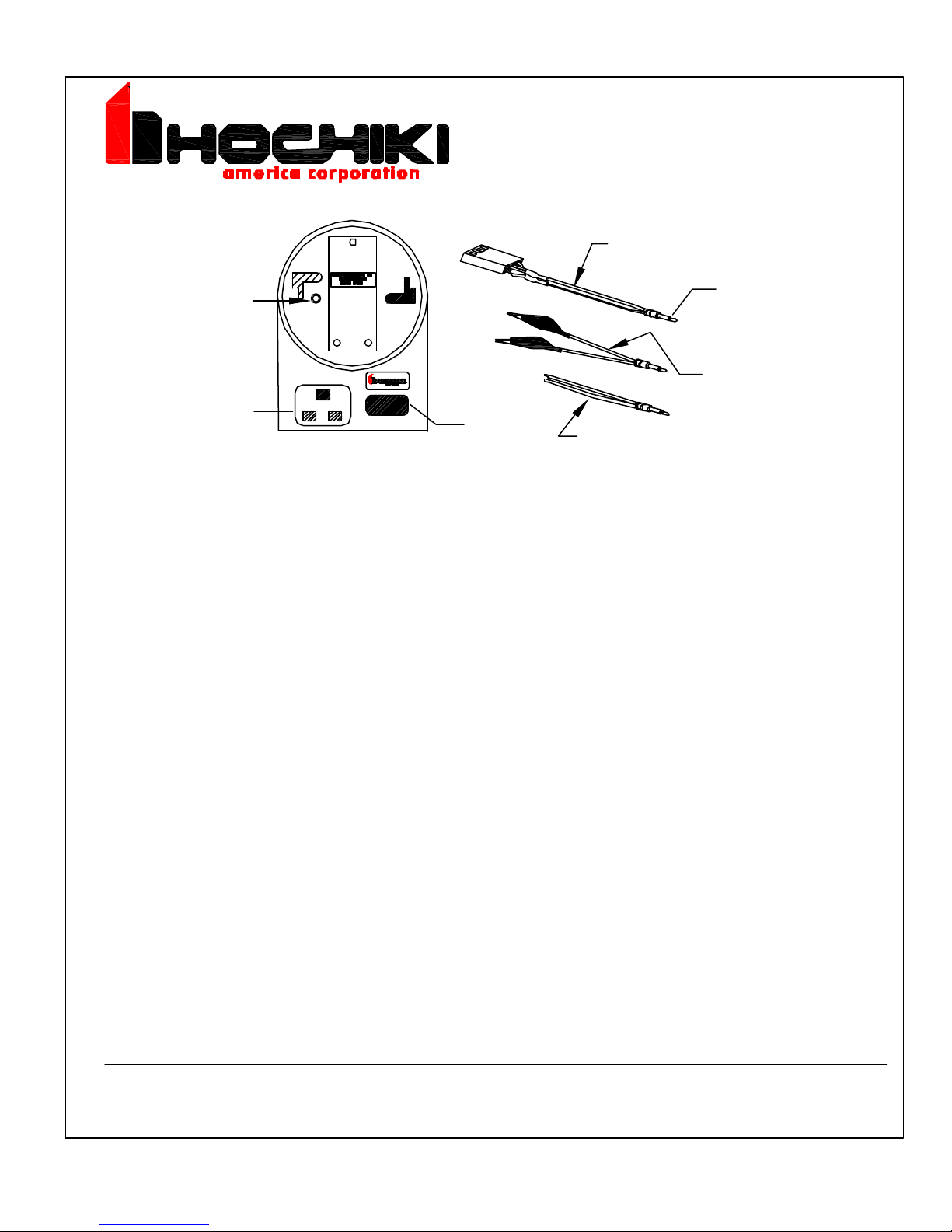
Remote Programming Cable
(All Modules except DCP-FRCME-S
and DCP-FRCME-P)
Remote Programming
Jack
Programming Buttons
Display
GENERAL DESCRIPTION:
TCH-B100-NS is designed for use with the following products:
Remote Programming Cable
(DCP-FRCME-S)
To Remote
Programming Jack
Remote Programming Cable
(DCP-FRCME-P)
ALG-V/ALG-EA
AIE-EA
ATG-EA
FRCME-4
FRCME-S
SOM
R2M
CZM
DIMM
PROGRAMMING BUTTONS
LEFT GRAY BUTTON
Analog Photoelectric Smoke Sensor
Analog Ionization Smoke Sensor
Analog Heat Sensor
DCP Fast Response Contact Monitor
DCP Fast Response Contact Module (Flying Leads; No Terminal Block)FRCME-P
DCP Fast Response Contact Module (Terminal Block)
DCP Signal Output Module
DCP Dual Relay Module
DCP Conventional Zone Module
DCP Dual Input Monitor Module
Power on. Automatically reads the address of a sensor. Subsequent
operations will advance the device address by ten.
RIGHT GRAY BUTTON
RED BUTTON
Power off. Advances the device address by one.
Stores the displayed addresss to the device and is used to read sensor
analog levels.
NOTE: PRIOR TO PROGRAMMING ENSURE BATTERY IS CONNECTED.
ADDRESS SETTING:
1.
Install sensor onto programmer, ensuring that sensor protrusions align with programmer grooves.
2.
Press the left gray button to switch programmer on. A battery check message will appear followed by
the devices address ( un-programmed sensors will read address 127).
3.
Set the required address by incrementing the left and right gray buttons (the display will show three red
flashing dots if the address being programmed is different from the device's current address).
4.
When the desired address is present press the red button to store that address. The three red dots on
the display will no longer be present.
HOCHIKI AMERICA CORPORATION
7051 Village Drive, Suite 100
Buena Park, CA 90621-2268.
DWG # HA-06-082
Page 1 of 2, 10-03
PART # 1700-09906
Page 2
 Loading...