

Page 1
Certain actions can cause permanent damage to the detect or. If the detector is subjected t o any of the following it should not
be used:
Dis-assembly and re-assembly, apart f r om chamber r epl ac em ent in the case of photoelectric smoke detectors (the
detectors cannot be r epaired and must be replaced in their entirety).
Impact or shock.
Suspected damage following a fire.
In the case of heat detec tors, touching the thermistor element.
These detectors m ust be subj ec t to periodic maintenance during regular service visits. This period should be outlined i n the
appropriate standar ds or rec om mendations. If there are no such standards existing, Hochik i r ec ommend that the minimum
period of maintenance should be 1 year and that the following should be taken into account:
A regular oper ation test should be perform ed using suitabl e test equipment (cert ain types of test equipment should not be
used in flammabl e/com bustible atmospheres).
A visual check for staining and mechanical dam age shoul d be m ade.
A magnetic test facility is incorporated int o both detectors which can be operated using a sui table magnet.
HOCHIKI INTRINSI CALLY SAFE SMOKE AND HEAT DETECTORS (AND
MOUNTING BASE) INSTRUCTIONS
Products Covered: SLR-E-IS Photoelectric Smoke Detector, DCD- 1E-IS Combined Rate of Rise
Heat Detector, YBN-R/4(IS) Electronics-Free Mounting Base
Introduction
These Detectors are certified by BASEEFA as suitable for use in hazardous atmospheres as detailed below. It is essential t hat
the detector s and base are installed and operated in conformance with the certific ation in order to remain safe. It is the
responsibility of the installer to ensure t hat the detectors and base are installed according to the certifi c ation requirements, and
it is recommended that the installation only be car ri ed out by qualified personnel.
The YBN-R/4(IS ) Base m ay onl y be used with Hochiki Intrinsically S afe specified detector heads. The use of other det ec tor
heads is expressly forbidden and may cause fire or explosi on.
A dust cover is included wit h these detectors to prevent cont ami nation during installation and prior to commissioning. The dust
cover must be removed for the detectors to operate.
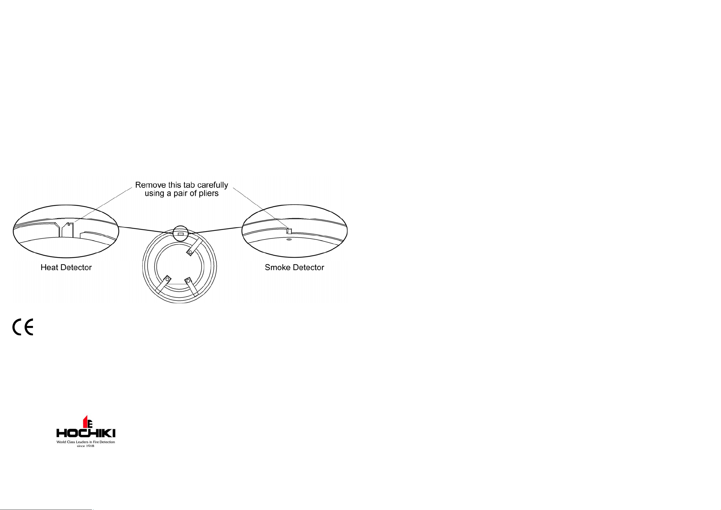
The detector s can be lock ed on to t he base by rem oving a plastic lug on the underside, please refer to the diagram below. The
locked detector c an then only be removed by using a special removal tool whic h is available from Hochiki Europe (UK) Ltd
(part number TSC-A 100/ALG).
DCD-1E-IS 0832-CPD-0121 05 EN54-5 Point type heat detectors
SLR-E-IS 0832-CPD-0113 05 EN54-5 Point type heat detectors
Classification - SLR-E-IS
This Detector has BASEEFA certification classificati on according to EN 60079-11:2007 and an ATEX Classification of
II 1 G Ex ia IIC T5 -20°C<Ta<55° C. Areas suitable for installati on: Category 1, 2 or 3 hazardous atmospheres, wit h a
maximum ambient temper ature of up to 55°C.
Classification - DCD-1E-IS
This Detector has BASEEFA certification classificati on according to EN 60079-11:2007 and an ATEX Classification of
II 1 G Ex ia IIC T5 -20°C<Ta<55° C. Areas suitable for installati on: Category 1, 2 or 3 hazardous atmospheres, wit h a
maximum ambient temper ature of up to 55°C.
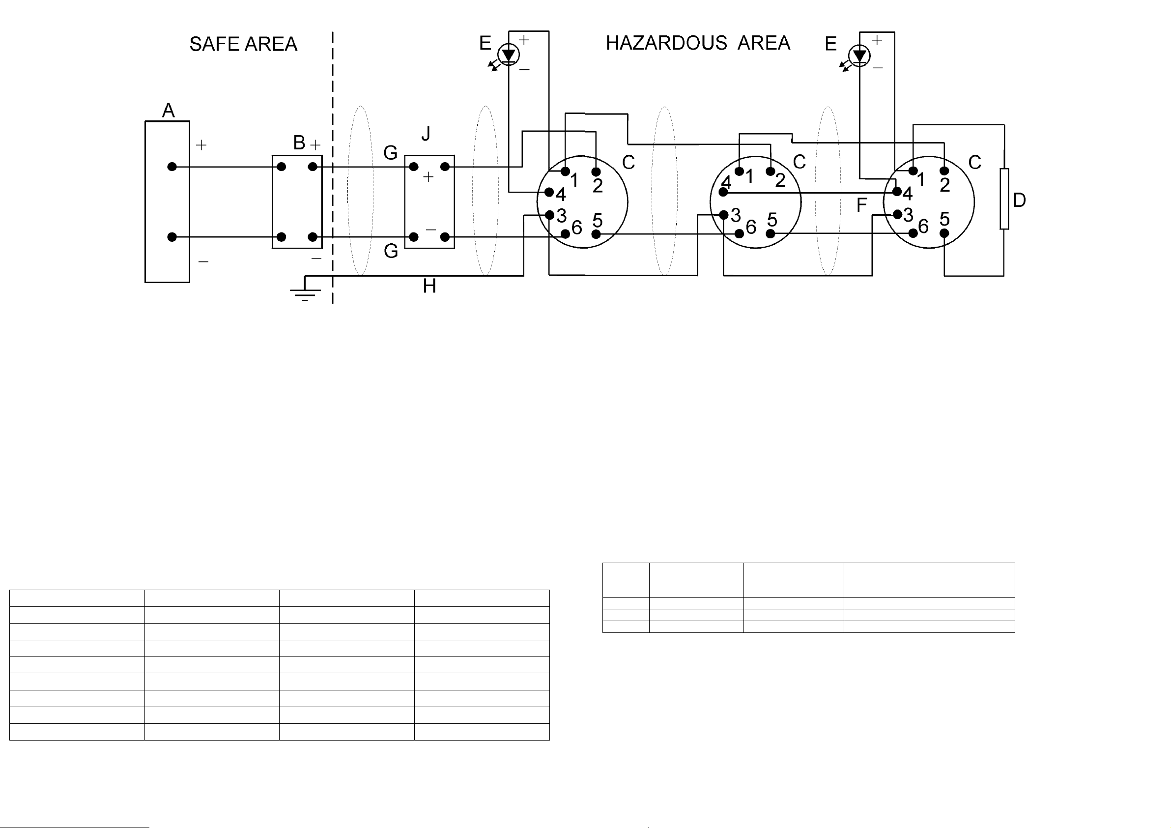
Refer to the system dr awing ov er leaf for important inf ormati on concer ning installati on/wiring requirements which must be
strictly observed in order to comply with BASEEFA certification. These detectors and base MUST be used with eit her a Zener
Diode Barrier or a Galvanic Isolator, using suitable models as detailed in the system drawing overleaf. The Zener Diode
Barrier or Galv anic Isolator should be install ed ac c or ding to t he manufac turer's instructi ons.
Note
These products have been designed to
Avoid physi c al injury or harm by direct or indirect contact
Not produce surface temperatures of accessible parts or radiation which could cause danger
Eliminat e any non- elec trical dangers
Not give ri se to dangerous conditions in the event of overload
Precautions
Hochiki smok e and heat det ec tors cannot be used to prevent a fire itself , t hey ar e intended only to detect certain charact er istics
of fire. When installing the detectors, check that t he location of each one has been planned according to appropriate fire
regulati ons and rec ommendations.
Hochiki detec tors are suitable for indoor use only. A detector shoul d not be installed in the following env ir onmental conditions:
Excessive am bient temperature.
Where excessive condensation or moisture is present.
Where corrosive gas or any other harmful agent is present .
Where flamm able dust or st eam is present.
Where obstruct ions are present which could impede the flow of air to the detector.
Where mechanical stresses could affect the det ec tor when fitted in accordanc e to these instructions.
Hoch iki Europe (UK) Ltd
Grosvenor Road, Gillingham Business Park,
Gillingham, Kent, ME8 0SA, England
Tele phone: +44(0)1634 260133 Facsimile: +44(0)1634 260132
Email: sales@hochikieurope.com
Web: www.hochikieurope.com
Hochiki Europe (UK) Limited 2-3-0-345/ISS7/OCT10 Hochiki Europe (UK) Limited 2-3-0-345/ISS7/OCT10
Hochiki Europe (UK) Ltd. reserves the right to alter the specification of its products from
time to time without notice. Although every effort has been made to ensure the accuracy of
the information contained within this document it is not warranted or represented by
Hochiki Europe (UK) Ltd. to be a complete and up-to-date description. Please check our
web site for the latest version of this document.
Page 2
Notes
1. The electrical ci r c uit in the hazardous area must be capable of withstanding an a.c. test voltage of 500 volts to earth or
frame of the equi pm ent, for a peri od of one mi nute without breakdown.
2. The installation must comply with National requirements.
3. The system must be marked wit h a durable label which should appear on or adjacent to the principal item of electrical
apparatus in the system or at the interface between the i ntrinsically safe and non-i ntrinsically safe circuits. This
marking shall include the word SYST or SYSTEM, for example “System No. BAS Ex 98D2264” or “BAS No. Ex
98D2264 SYST”.
A. Unspecified equipment except that no voltage shall exceed 250V with respect to earth.
B. EITHER:
Any BASEEFA Certified shunt safety Zener Diode Barrier with the following parameters:
30V or less
200mA or less
1W or less
2
The barrier eart h m ust be connect ed v ia a high integrity connecti on, using an insulated conductor equivalent to a 4mm
conductor, such t hat the impedance from the point of connection to the main power system earth is less than 1 ohm.
OR:
Any one channel from the f ollowing BASEEFA Certified Galvanic Isolators:
Type Number Um=250V I.S. Output Certificate No.
MTL 3043 2-3 5/6-7/8 Ex86B2285
MTL 40612Channel 9-8 or 12-11 1/2-3 or 4/5-6 Ex94C2040
MTL 5061 2Channel 9-8 or 12-11 1/2-3 or 4/5-6 Ex96D2426
MTL5561 2 Channel 9-8 or 12-11 1/2-3 or 4/5-6 BASEEFA09ATEX0027
P&F KFD0-CS-Ex1.51 11-12 1-2 Ex96D2152
P&F KFD0-CS-Ex2. 51 11-12 or 9-8/ 10 1-2 or 4-5 Ex96D2152
P&F KFD0-CS-Ex1.51P 11-12 1-2 Ex96D2152
P&F KFD0-CS-Ex2. 51P 11-12 or 9-8/10 1-2 or 4-5 Ex96D2152
Note: Earthing requirements as described above for Zener Diode Barriers, is not requi r ed with Galvanic Isolators.
copper
C. Up to 20 SLR-E-IS Intrinsically Safe Photoelectric Smoke Detectors complete with YBN-R/4 IS Bases, BASEEFA Certificate
BAS01ATEX1281
OR:
Up to 20 DCD-1E-IS Intrinsically Safe Heat Detectors complete with YBN-R/4 IS Bases, BASEEFA Certificate No
BAS01ATEX1021
OR:
A combinati on of each type to a maximum of 20 units.
2
D. End-of-line r esi stor . The end-of-line resistor must have a body surface area of 230mm
E. Optional Rem ote I ndic ator consisting of Light Emitting Diode (LED) only. The LED must have a surfac e ar ea of 230mm
or more.
2
or
more. The interconnec ting cable to any Remote Indicator( s) is to be considered as part of the inter c onnec ting cable described
at G below.
F. Optional i nterc onnec tion for sharing a single Remot e Indicator between any number of SLR-E-I S or
DCD-1E-IS/ YBN-R4/IS Detector/Base combi nations as shown above. The terminal 4 in each base may be interconnect ed as
shown at F above and a single Rem ote I ndic ator connected to any one such base. The interconnec ting cable between any
terminals 4 and the wiri ng to any Remote Indicator is to be considered as part of the interconnecting cable described at G
below.
G. Interconnecting cable having the following maximum parameters:
Group
Capacitance
C
µF
Inductance
L
mH
Inductan ce to Resistance ratio
L/R
µH/ohm
IIC 0.07 0.62 36
IIB 0.56 1.86 146
IIA 1.82 4.96 286
H. Optional cable screen. If used, this must only be connected to earth within the safe area and must be isolated f r om the
electric al ci r c uit and must be capable of withstanding an a.c. test v oltage of 500 volts for a period of one minute without
breakdown.
J. Up to 20 optional dev ic es, for example switches such as manual call points having appropriate BASEEFA Certification for
use in the intended hazardous environment (Hochi ki part no. CCP-IS) or otherwise cl assif ied as simple apparatus according to
BS EN 60079-11:2007. Such devic es may be fitted with a resistor in seri es wit h the switc h and /or an end-of-line resistor as
per D above. Where such a resistor is used it must have a body surface area of 230mm
2
or more (typical resistanc e 470 - 680
ohm).
Hochiki Europe (UK) Limited 2-3-0-345/ISS7/OCT10 Hochiki Europe (UK) Limited 2-3-0-345/ISS7/OCT10
 Loading...