

Page 1
HOCHIKI CDX MARINE DETECTOR RANGE
INSTALLATION INSTRUCTIONS
Products Covered: SLR-E3M, SLR-E3NM, DCD-AE3M, DCD-CE3M, c/w YBN-R/6M Base
The Conv entional M ar ine Detector s l isted above all use the c ommon mounting base YB N- R/6M which is elec tronics-free
and features a t hird terminal for Remote Indi c ator output. The Marine Bac k B ox (MBB- 1) shoul d be used i n c er tain
locati ons and conditions (see MBB- 1 Instructi ons for f ur ther details).
Follow the guidelines bel ow before instal lation and maint enanc e. Hochiki cannot guarantee a detector's performanc e if
these guidelines are not followed.
Caution
Hochiki CDX Mar ine Detectors cannot be used to prev ent fire itsel f; t hey ar e only intended to detect a cer tain
characteristic of fire. The DCD marine range of detectors is used to detect changes i n temperat ur e and c annot detect
smoke and other phenomena. When installing the detector, check that the location of each one has been planned
according t o appr opr iate fire regul ations or recommendations. Certai n ac tions can cause permanent damage to the
detector, and if subjec ted to any of the f ollowing, it should not be used:
Situations in which condensation exists Smoke detectors only
Situations in which corr osi ve gases exist All det ectors
Impact or shock All det ectors
Situations in which obstacles exist, whic h c ould impede airflow to the detec tor All det ectors
Situations in which dust or steam exist Smoke detectors only
Disassembly and re-assembly
(except chamber replacement of photoelectri c smoke detector s)
Touching the thermistor locat ed in centre of detect or Heat detector s onl y
All det ectors
If in any doubt, always refer to relevant certification r egarding appropri ate detector use.
If damage is suspected after a fire has occurred, the detector shoul d be replaced. After install ation, all detect ors on the
fir e alarm system should be tested t o c onfirm correct operation. Only sui tably tr ained engineers should carr y out
installation and maintenance. The detect or must be subject to periodi c maint enanc e dur ing regular servi c e vi sits. Thi s
period should be outlined in the appropriat e standards or recommendations. I f there ar e no such standar ds existing,
Hochiki recommend that the minimum period of mai ntenance should be one year and that the f ollowing should be t ak en
into account:
A regular operation test should be per formed.
A visual check for staining and mechanical
damage should be made.
A dust cov er is incl uded wi th the detector to prevent contaminat ion during installation. The du st cover must be
removed for the detector to operate.
Operation should only be checked by equipment that i s
capable of exceeding the required det ec tion threshol d.
Detector operation should not be tested with a naked
flame or open fire.
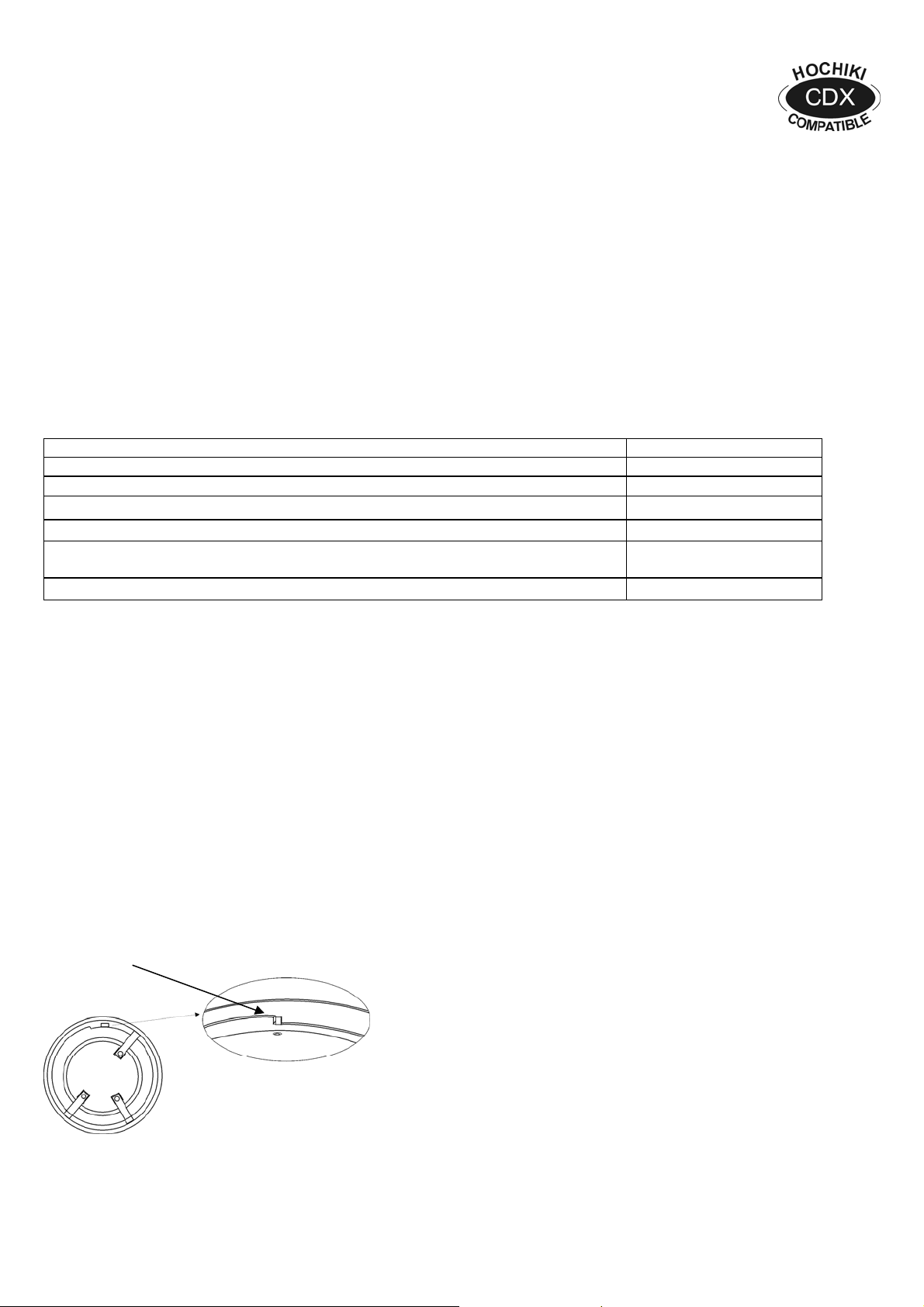
Head Locking Mechanism
Remove tab carefully using a pair of pliers
The CDX range of Mar ine Detectors can be locked onto the
base by removing a pl astic lug on t he under side of the
Detector. The Detector c an then only be remov ed by usi ng
a special Removal Tool ( TSC-A100/ALG), which i s
available from Hochiki Europe.
Wiring
The wiring diagram for the conventional marine detector base should be made as shown.
2-3-0-434/ISS3/OCT09
Page 2
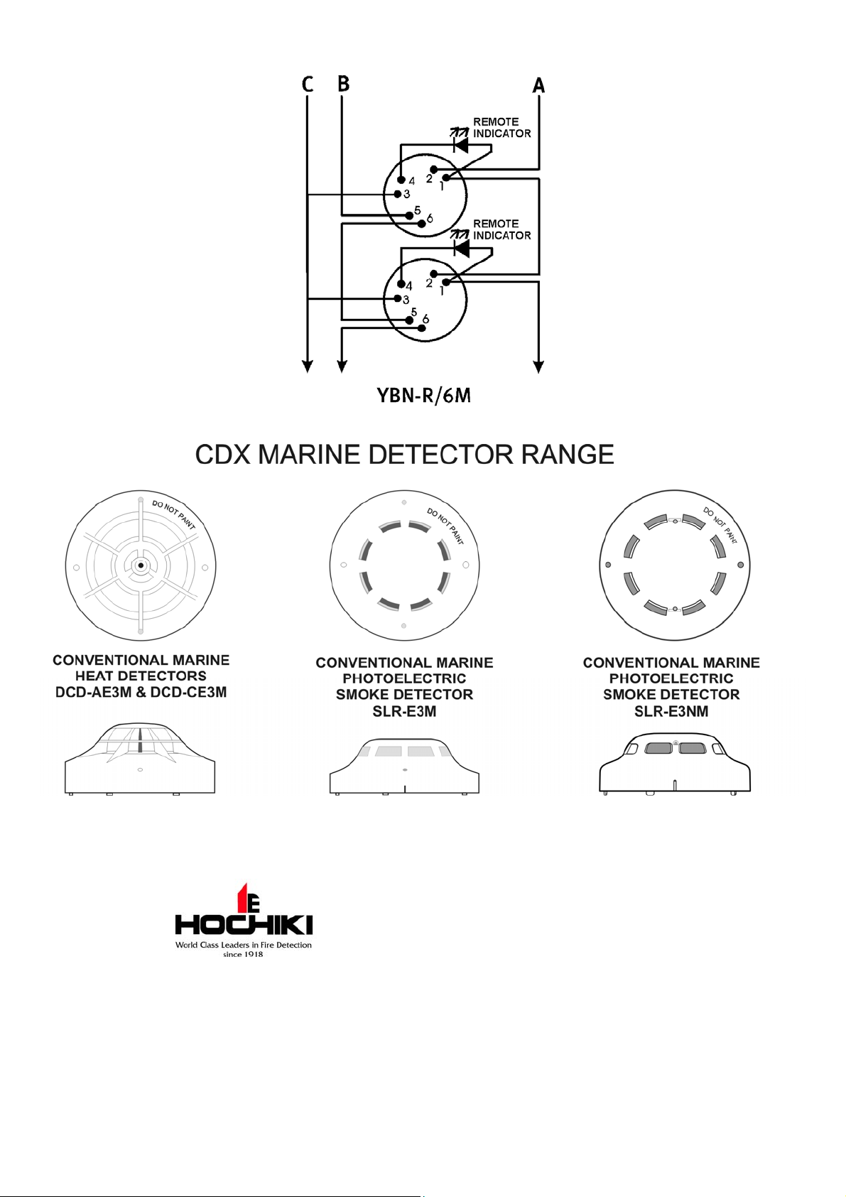
A: Zone (+), B: Zone (-), C: Cable Screen
A list of com patible Control Panels is available on r equest .
Hochiki Europe (UK) Ltd
Grosvenor Road, Gillingham Business Park,
Gillingham, Kent, ME8 0SA, England
Telephone : +44(0)1634 260133 Facsimile: +44(0)1634 260132
Email: sales@hochikieurope.com
Web: www.hochikieurope.com
Hochiki Europe (UK) Ltd. reserves the right to alter the
specification of its products from time to time without notice.
Although every effort has been made to ensure the accuracy
of the information contained within this document it is not
warranted or represented by Hochiki Europe (UK) Ltd. to be
a complete and up-to-date description. Please check our
web site for the latest version of this document.
2-3-0-434/ISS3/OCT09
 Loading...