

Page 1
HOCHIKI CONVENTIONAL DETECTOR RANGE INSTALLATION
INSTRUCTIONS
Products Covered: Detectors - SLR-E3/SLR-E3N, DCD-AE3, DCD-CE3, DFJ-AE3, DFJ-CE3
Bases - YBN-R/6, YBN-R/6SK, YBO-R/6PA, YBO-R/6R, YBO-R/6RN, YBO-R/6RS
Introduction
The Conv entional Detectors listed abov e all utilise three terminals, which means they can dri ve a remote indicator.
They also operate within a wide voltage range (9.5 - 30V) allowing i nstallation within both fi r e A ND secur ity
systems. Each detec tor can use a common mount ing base (YBN-R/6) whic h is electr onics free, or any other base
from the range of special bases as shown below:
Detector Base Description
SLR-E3
SLR-E3N*
DCD & DFJ Ranges
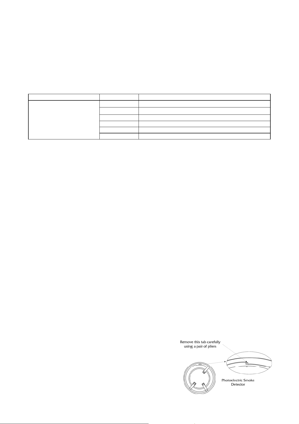
* When using older variants of those mounting bases listed above, the three locating tabs on the bottom edge of the
SLR-E3N will need to be car ef ully removed with pliers (see drawing on page 2).
Please observ e the guidelines below before installat ion and maintenance. Hochiki cannot guarantee a detector's
performance if these guidelines are not foll owed.
YBN-R/6 Standard Base
YBN-R/6SK Base with in-l ine Schottk y Diode
YBO-R/6PA Base compatible with Protector Alarms Systems
YBO-R/6R Relay Base (Latching)
YBO-R/6RN Relay Base (Non-latching)
YBO-R/6RS Relay Base (Lat c hing with Schottky Diode)
Caution
Hochiki detectors cannot be used to pr event fire itself, they ar e only int ended to detect a cer tain characteristi c of
fir e. The detect or DFJ(Range) and DCD(Range) ar e used to detect conditions and changes in temperature and
cannot detect smoke and other phenomena. When instal ling the detector, c hec k that the l oc ation of each one has
been planned according to appropri ate fi r e regulati ons or r ec ommendations.
Please not e: - These Detect ors are designed for indoor use only.
Certain actions can cause permanent damage to the detector. If the detector is subjected to any of the following it
should not be used (or it shoul d be located where the phenomenon does not exi st) :
Situations in which condensation exist s.
Situations in which corr osi ve gases exists.
Situations in which obstacles exist, whic h c ould
impede airflow to the detect or .
Situations in which dust or steam exists
If damage is suspected after a fire has occurred, the detector shoul d be r eplaced. After installat ion, all detector s
on the fire alarm system should be tested to conf irm c orrect operat ion. Onl y suitably t rained engineers should
carry out installations and maintenance. The detector must be subject to periodic maint enanc e dur ing regular
servi ce visits. This period should be outlined i n the appropriat e standards or recommendations. If ther e are no
such standards existi ng, Hochiki recommend that the minimum period of maintenance should be 1 year and that
the following should be tak en into account :
A regular operation test should be per formed.
A visual check for staining and mechanical
damage should be made.
Disassembly and re-assembly (except SLR-
E3/SLR-E3N maintenance) .
Impact or shock.
Touching the thermistor locat ed in the centr e of
the detector (DFJ Range and DCD Range Heat
detectors only ) .
Operation should only be check ed by equipment
that is capable of exceeding the r equired
detection threshold. Detector operation should
not be tested with a naked flame or open f ire.
A dust cov er is included with the detec tor to prevent cont aminat ion
during installation. T he dust co ver must be removed f or the
detector to operate.
Head Locking Mechanism
The detector s can be locked onto their relevant bases by remov ing
a plastic lug on the underside of the Detector. The Det ec tor can
then be removed by using a r emoval tool which is available f rom
Hochiki E urope (UK) Ltd.
2-3-0-500/ISS10/NOV09
Page 2
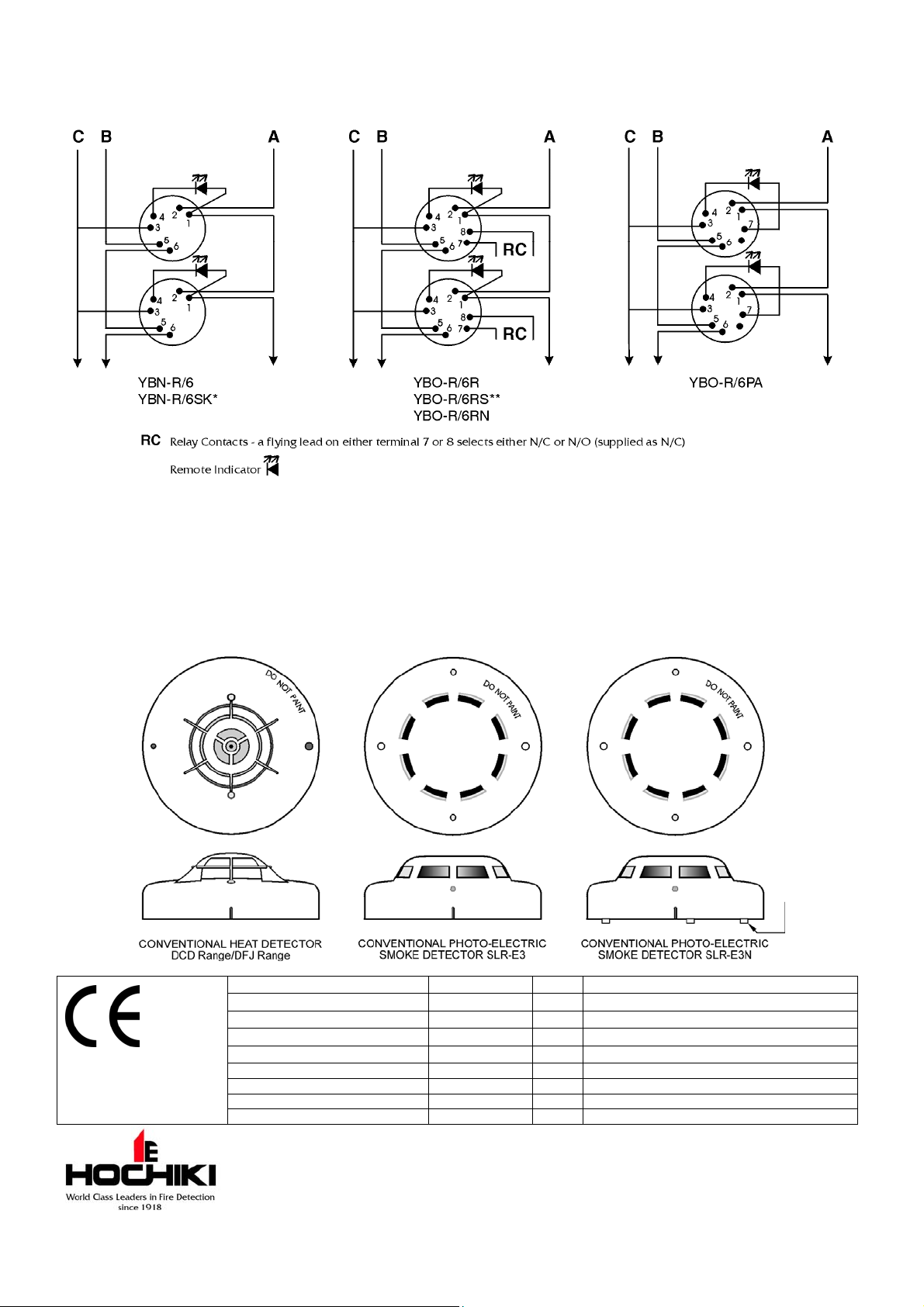
Wiring
The wiring diagram for the conventional detec tor base should be made as shown.
A: Zone (+) B: Zone (-) C: Cable Screen
*The Schottky Diode Bases can easily be converted into non-Schottky versions by removing the Schottky diode, which is fitted between terminals 1 and 2.
**The Schottky Diode Bases can easily be converted into non-Schottky versions by cutting out and removing the Schottky diode, which is soldered on the
underside between terminals 1 and 2.
Note
The YBO-R/6RN base will automatically reset the detector every 8 - 15 seconds after it has entered an alarm
state. If the detector remains above its alarm threshold after a reset the LEDs will illuminate again. This will
continue until a reset is achieved. The relay contacts (and Remote I ndicator) will not change state until t he r eset
is successful.
Note: When
using older
variants of
those mounting
bases listed
overleaf, the
three locating
tabs on the
SLR-E3N will
need to be
carefully
removed with
pliers.
Protocol specified in TI/006
DCD-AE3 0832-CPD-0116 05 EN54-5 Point type heat detectors
DCD-CE3 0832-CPD-0117 05 EN54-5 Point type heat dete ctors
DFJ-AE3 0832-CPD-0118 05 EN54-5 Point type heat detectors
DFJ-CE3 0832-CPD-0119 05 EN54-5 Point type heat detectors
SLR-E3 0832-CPD-0111 05 EN54-7 Point type smoke detectors
SLR-E3N 0832-CPD-0614 08 EN54-7 Point type smoke detectors
YBO-R/6R 0832-CPD-1112 09 EN54-18 Input/Output modules
YBO-R/6RS 0832-CPD-1113 09 EN54-18 Input/Output modules
YBO-R/6RN 0832-CPD-1114 09 EN54-18 Input/Output modules
Hochiki Europe (UK) Ltd
Grosvenor Road, Gillingham Business Park,
Gillingham, Kent, ME8 0SA, England Telephone:
+44(0)1634 260133 Facsimile: +44(0)1634 260132
Email: sales@hochikieurope.com
Web: www.hochikieurope.com
Hochiki Europe (UK) Ltd. reserves the right to alter the
specification of its products from time to time without notice.
Although every effort has been made to ensure the accuracy of
the information contained within this document it is not warranted
or represented by Hochiki Europe (UK) Ltd. to be a complete and
up-to-date description. Please check our web site for the latest
version of this document.
2-3-0-500/ISS10/NOV09
 Loading...