

Page 1
HOCHIK I SDP-2 DUCT PROBE
INSTALLATION INSTRUCTIONS
Introduction
Hochiki's Duct Probe housing allows a standard
photoelectric smoke detection device, either a
conventional detector or an analogue sensor, to be
mounted on the outside of an ai r duct f or t he purpo se of
monitoring t he air within the duct. Air wit hin the duct is
drawn via a pipe into the duct probe's housing. This
allows constant sampling with a standard, LPCB
approved smoke detector and makes smoke detection
within the duct simple, effective and easy to maintain.
Compatibl e Hochiki devices that can be used within t he
SDP-2 are:
ESP ACA-E (inc all variants)
ALG-E (inc all variants)
ALG-EN (inc all v ari ants
CDX SLR-E3 (inc all variants)
SLR-E3N (inc all variants)
Compatibl e Hochiki Bases that can be used within the
SDP-2 are:
ESP YBO-R/SCI, YBN-R/3
CDX YBN-R/6, YBN - R /6 SK, YBO-R /6 R , Y BO-R/6RN
and YBO-R/6RS.
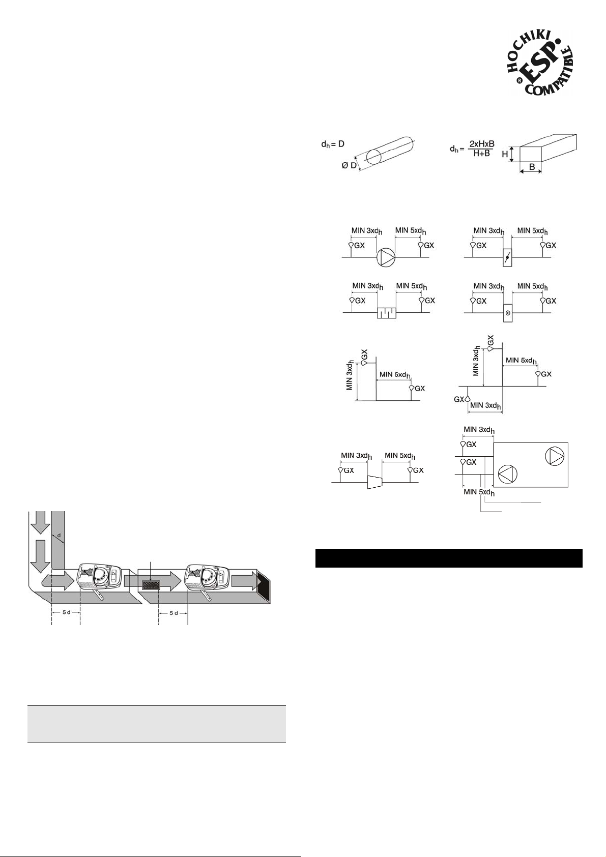
Hydraulic Diamet ers
Circular Duct Rectangular Duct
Location Examples
(GX represents duct probe)
Fan Damper
Silencer Battery
Mounting Position
The SDP-2 should be installed with the arrow on the
cover corresponding to the direction of airflow in the
duct. The SDP-2 can be placed horizontally or vertically,
on the top, side or bottom of the duct. Hochiki
recommends that the SDP-2 is mounted away from
heating, cooli ng or humidity devices f ollowing the same
guidelines f or fl ow m onitors.
Exampl e of location after
change of duct direction
A distance of three times the duct diameter should be
left before a dam per, filter or change of duct direction,
and five times the diameter after these devices.
NOTE: The word “diamet er ” has been used througho ut.
In the case of square-section ducts this should be read
to mean width.
Exampl e of location
after air inlet
Change of duc t dir ec t i on Duct branching
Duct narr ow i ng or expansi on Air “contr ol“ eq ui p ment
Installation Procedure
STEP 1 - Selecting Pipe Length
The supplied 600mm sampling pipe can only be used
with ducts up to a maxim um diamet er of 600mm, but the
pipe can be shortened if r equired (see Step 2).
For ducts with a diameter greater than 600mm use the
1200mm sampling pipe c ut t o si z e but penet r ating the
whole width of the duct (see “Large Diameter Ducts” on
Page 2).
For ducts with a diameter greater than 1200mm contact
Hochiki Europe Customer Support for advice
(psupport@hochikieurope.com).
Air Flow Paramete rs
The SDP-2 Duct Probe will oper ate within the following
air velocit y range and should be installed to meet thi s
requirement: 1.0ms
-1
to 10.0ms-1
Hochiki Europe ( UK ) Limit ed Page 1 of 4 2-3-0-456/IS S 5/FEB09
Page 2
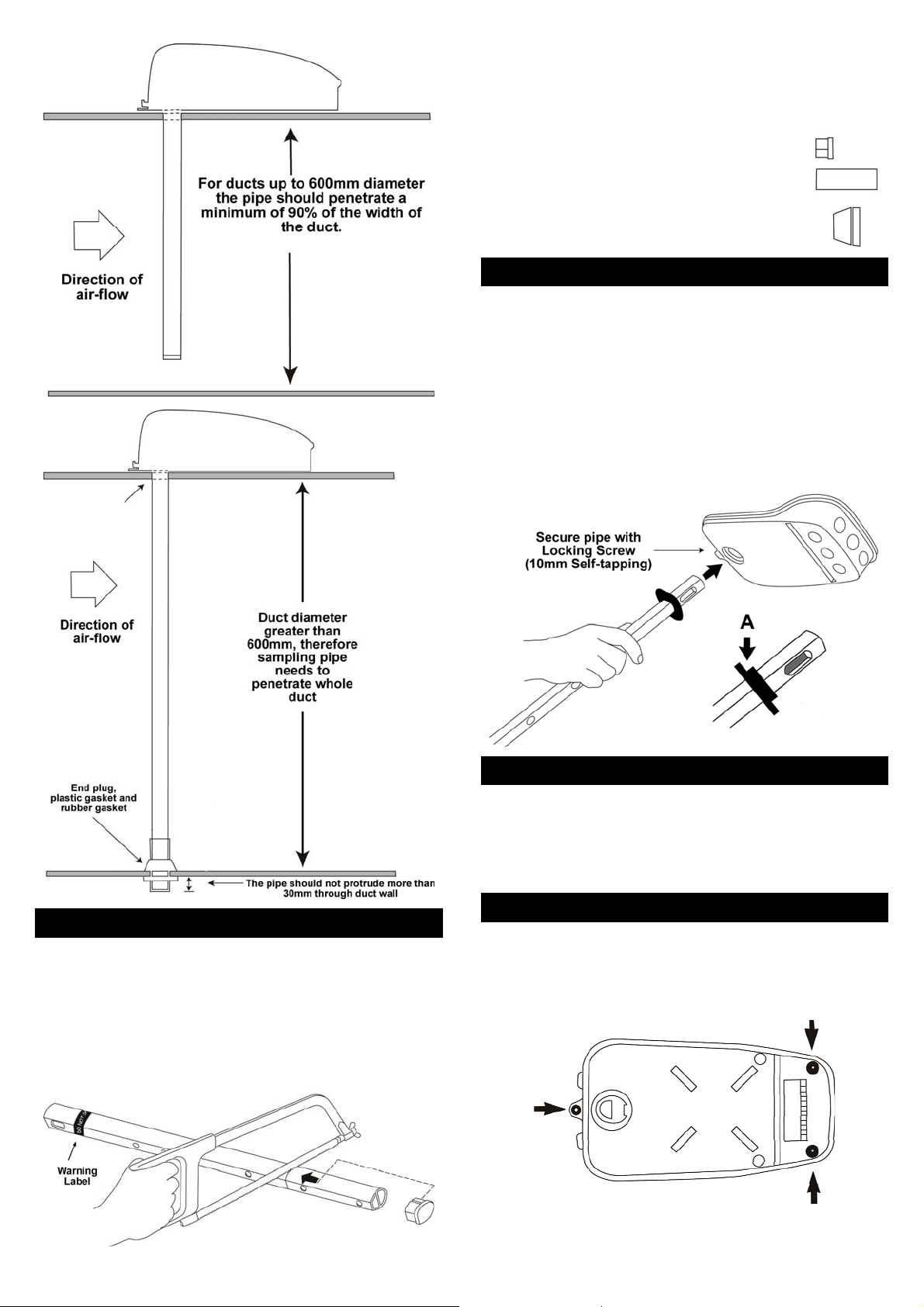
Large Diameter Ducts
When using a sampli ng pipe within a duct greater than
600mm diamet er the pipe shoul d penetrate the whole
duct:
Shorten the pipe to corr ec t length if
required
Insert the end pl ug
Fit the end plastic gasket
Fit the rubber gasket
STEP 3 - Fit Sampling Pipe to SDP-2
Before fitting the pipe to the unit, remove the cover and
the air-flow block. With the sampling pipe cut to lengt h,
fit it to the underside of the SDP-2 unit:
Mount the gasket (A ) on to the pi pe the cor r ect way
round (see below)
Push the pipe into t he hole in the undersi de of the
unit (the pi pe is specially shaped to only fit the
correct way round).
Tighten the locki ng screw to secure t he pipe to the
unit.
STEP 2 - Adjusting Pipe Length
After measuring t he diameter of the duct and
deducing the lengt h of pipe required, shorten the
pipe if necessary. T he pipe shoul d penetrate a
minimum of 90% of the widt h of the duct .
Do not cut the end of the pipe with warni ng label.
Only cut between sampling holes.
Once cut to length, insert the end plug.
STEP 4 - Drill Hole in Duct
Before mounting the SDP-2, drill a hole in the duct for
the sampling pipe:
Without brac k et - hol e diam eter = 35mm
With bracket - hol e diam eter = 48mm (see “Using
the Optional Mounting Bracket” on page 4).
STEP 5 - Mounting the SDP-2 on the Duct
Carefully mount the SDP-2, inserting the sampling
pipe into the hole in the duct wall.
Secure the SDP- 2 with t he suppli ed three 25mm
Self-tappi ng scr ews (positions shown).
Hochiki Europe ( UK ) Limit ed Page 2 of 4 2-3-0-456/IS S 5/FEB09
Page 3

NOTE - IMPORTANT! The arrow on the SDP- 2 cover
must have the same direc tion as the air-flow within the
duct.
Supplied Screw Guide
25mm - 3 off
(Self-tapping)
20mm - 2 off
(Self-tapping)
10mm - 1 off
(Self-tapping)
STEP 6 - Installing Detector/Sensor/Base
Connect the base to the wir es fr om the t erminal
block within the SDP - 2. Use the wiri ng guide on
page 4.
External cabling should be passed through the
knock-out holes located at the end of the SDP-2
housing and suitable glands must be used. Connect
the cabling to the termi nal block using the wiring
guide on page 4.
Once base is fix ed and connect ed, mount the
sensor/detector ensuring the rib lines up with one on
the base and points towards the sam pling pipe.
The smoke detector or sensor i s mounted on a base
which is fix ed and wired to the SDP - 2. Depending on
which type of base is bei ng used, the spacer (supplied)
may be required to raise the height of the detector or
sensor. The table below identifies when the spacer
should be used:
RANGE BASE USE SPACER
ESP
CDX
If using the spacer, first slot this onto the fixing posts
marked “C” inside t he S DP-2 ensuri ng it is the
correct way up (see diagram ) and that the cable ribbon is underneat h. Then fix the base to the SDP2 on top of the spacer with the two 20mm screws
(supplied) using the fixing posts marked “ U” (see
diagram) passing the c able-ribbon through t he base.
Ensure that the rib ( see “R” below) on the side of the
base is pointing towards the sampling pipe.
YBO-R/SCI NO
YBN-R/3 YES
YBN-R/6 YES
YBN-R/6SK YES
YBO-R/6R NO
YBO-R/6RS NO
YBO-R/6RN NO
NOTE - IMPORTANT! When using Hochi ki
CONVENTIONA L Opti c al Smoke Detectors. If only one
smoke detect or i s connected to the Control Panel, this
detector’s base should be f itted with an End Of Line
(EOL) device compatible with that Control Panel. When
several smoke det ec tors are connected to one Control
Panel, the EOL device shoul d be c onnec ted to the last
base. There should only be one EOL dev ic e per zone.
STEP 7 - Re-fitting Air-Flow Block
Carefully sl ot t he air -flow block back onto the SDP-2
ensuring it m akes good contact with the base of the unit.
NOTE - IMPORTANT! Once the unit is assembled and
fitted, check the fl ow indicator. This is a metal disc
suspended on a wire in t he recess on top of the air-flow
block. Note that the indicator oscillates but does not
rotate. If the indic ator does not move, you should firstl y
check the air-flow within the duct and secondly, t he
positioning of the SDP-2.
STEP 9 - Testing Smoke Detection
To test the detect or /sensor before fitting t he cover to t he
SDP-2 use smoke from a match or an approved test
gas.
Hochiki Europe ( UK ) Limit ed Page 3 of 4 2-3-0-456/IS S 5/FEB09
Page 4

STEP 10 - Fitting Cover
Fit the cover ensuri ng r ear tabs (B) ar e loc ated properly.
Then secure the cover in place with supplied screws
ensuring the unit is air-tight.
NOTE - IMPORTANT! Do not drill any hol es i n the
cover for signs/labels etc. Holes will cause air l eak age
and seriously distur b the function of the detect or .
Check that the pl astic plug of the test hole is also
air-tight.
Check that the flow indicator oscillates ensuring
proper air-flow through the detector.
It is recommended t hat sm ok e from a sm ok e
generator is i ntroduc ed into the duct to check the
function of the det ec tor.
Trouble Shooting
If only the Control Panel indicates an alarm/fault:
Check that the EOL device is fitted in the last
smoke detect or base on the zone (c onventional
panels only).
Check that the EOL device is the correct type
(conventi onal panels only).
Check the loop for bad c onnec tions or short-circuits.
Check the detector base with a voltmeter for approx
24Vdc and ensure the voltage is the correct polarity.
If the Smoke Detector and Control Panel indicate an
alarm without smoke (and cannot be reset):
Check the detector; it may be contaminated with dirt
or condensation.
Replace the detect or as it m ay be faulty.
Terminal Block to Base Wiring Diagram
Refer to LOOP/ZONE CABLES column featuring the
intended mounting base. Wire the loop/zone cables to
the terminal block within the SDP-2 as shown. Connect
the coloured wir es fr om the t erminal block to the base
terminals as shown.
NOTE: When using the YBO- R/6R, YBO - R/6RN or
YBO-R/6RS bases - remov e the crimp from the ends of
the BROWN (6) and WHITE (7) wires bef or e att em pting
to connect to the mounting base terminals.
Using the Optional Mounting Bracket
When installi ng the SDP-2 on circular ducts or on
insulated rec tangular ducts use the optional B r ac k et
(SDP-BRACKET) . The brack et can also be used on
ducts with a diameter as small as 100mm.
The SDP-BRACKET is supplied flat and can easily
be bent or shaped to fit a circular or rectangular duct.
When using the brack et t he diam eter of the hole in
the duct wall should be 48mm .
The bracket shoul d be fixed to the duct wall with
appropriate fixings.
The supplied rubber gasket shoul d be used.
R=RED, BL=BLUE, P=PINK, GY=GREY, Y=YELLOW, GN=GREEN,
BR=BROWN, W=WHITE
Hochiki Europe (UK) Ltd
Grosvenor Road, Gillingham Business Park,
Gillingham, Kent, ME8 0SA, UK
Telephone: +44(0)1634 260133
Facsimile: +44(0)1634 260132
Email: sales@hochikieurope.com
Web: www.hochikieurope.com
Round Duct Insulated Rectangular Duct
Final Checks
The arrow of the cover must have the same
direction as the airflow in the duct.
Check that the rubber gasket between the cover and
bottom of the SDP-2 is air -tight.
Hochiki Europe (UK) Ltd. re serves the right to alter the specification of its products
from time to time without notice. Although every effort has been made to ensure the
accuracy of the information contained within this document it is not warranted or
represented by Hochiki Europe (UK) Ltd. to be a complete and up-to-date description.
Please check our web site for the latest version of this document.
Hochiki Europe ( UK ) Limit ed Page 4 of 4 2-3-0-456/IS S 5/FEB09
 Loading...