

Page 1

IFD-E(IS)
Intrinsically Safe Flame Detector
User Manual
Page 2

2 Hochiki Europe ( UK ) Ltd
General
Description
This Install ation Guide gives information on the intrinsically safe (I.S.) version of t he flame detectors that
have been approv ed by BASEEFA (British Approvals Service for Electrical Equipment in Flammable
Atmospheres). The requirements of the European Community Directive 94/ 9/EC, t he ATmosphere
EXplosives AT E X Directive have been met. The approval have been accessed to European Standards
EN 50014, EN 50020 and EN 50284.
The detector s are cer tif ied
The range comprises single infra-red (IR), dual infra-red (IR²) and tri ple infra-red (IR³ ) flam e detectors.
The detector housings are available in zi nc met al alloy or stainless steel and also stai nless steel
(antistati c ) glass fi lled polycarbonate.
The guide also provi des i nformation on intri nsi c safety, the applicati on, maintenance, installation and
adjustments of the detectors. Reference to ot her indiv i dual detector publi c ations can be made for more
information on none intrinsically safety issues. These public ations are available on request.
II 1 G EEx ia IIC T4 and can be used with all listed gase s.
Introduction to Intrinsic Safety
There are many places where an explosive mixture of air and gas or vapour is or may be pr esent
continuously , intermittentl y or as a result of an ac ci dent. These are defined as hazardous areas by BS
EN 50014:1998, El ect ri c al appar atus for potentially explosiv e atmospheres – General requirem ents.
Hazardous areas are common in petroleum and chemical engineering plants and in f act ori es proces si ng
and storing gases, solvents, paints and other v olatile substances.
Electri c al equipm ent for use in these areas needs to be designed so that it cannot ignite an explosive
mixture, not only in normal operation but also in fault conditions. There ar e a number of met hods
available to achieve this – oil immersion, pressuri se d appar atus and powder fill ing, for example, but the
two most common used are flam epr oof enclosures and intrinsic safety.
Flameproof equipment is contained i n a box so strong that an i nter nal explosion will neither damage the
box nor be transmitt ed outside the box. The surface must remain cool enough not to ignit e the explosive
mixture.
When flameproof equipment is interconnected, flameproof wiri ng must be used. This method is most
valuable when high power l evels are unavoidable but it is not acceptable for areas in which an ex plosive
gas/air mixt ur e m ay be conti nuousl y present or present for long per iods.
For this reason these flame detectors are made int rinsically safe rather than fl am epr oof. Intrinsic ally safe
equipment operates at such low power and with such small amounts of stored energy t hat it i s incapable
of causing ignition:
In normal conditions
With a single fault (for ib type of protection c ode)
With any combination of two faults (for ia type of protection code)
In any of these conditi ons every component must remain cool enough not to ignite gases for which it is
approved. See Table 2
Classification of Hazardous Areas
EN 50014 states that el ec trical apparatus for potentially explosive atm ospheres is divided into:
Group I: Electrical appar atus for mines susceptible to fire damp;
Group II: Electri c al appar atus for places with a pot entially explosive atm osphere, other than
mines susceptible to fire damp.
2-3-0-809/ISS2/JUL07
Page 3
Hochiki Europe ( UK ) Ltd 3
These flame det ector s are designed to meet the requirements of Group II apparat us. For the type of
protection “i” intrinsi c ally safe, Group II is subdivided into Equi pm ent Cat egories, Type of Expl osive
Atmosphere (Table 1), Type of Protection Code (Table 2), Temperature Class (Table 3) and Gas Group
(Table 4).
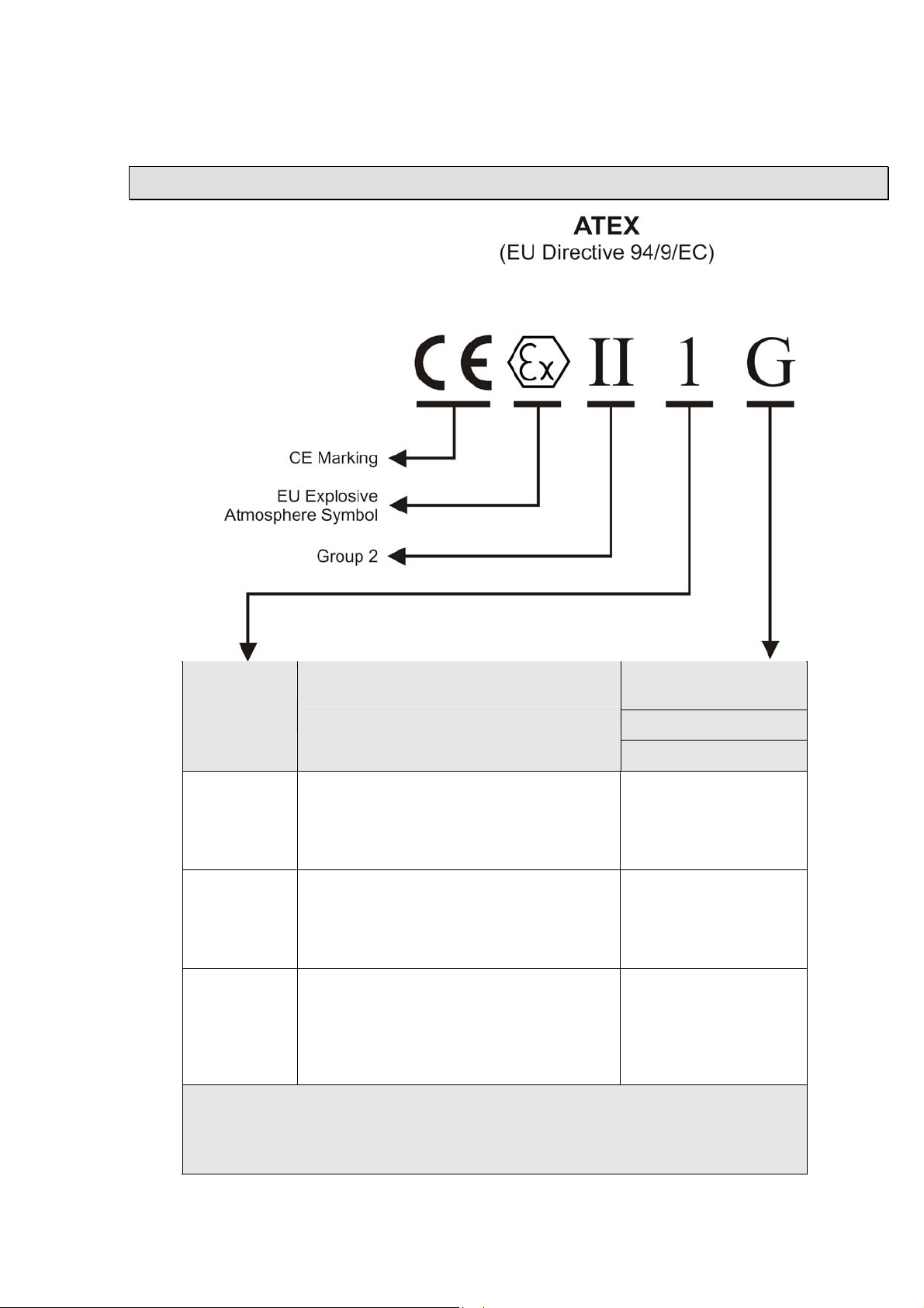
Equipment Markings
Type of Explosive
Equipment
Category
Definition
Atmosphere Group II
G - gas vapour mist
Zone
1 - very high level of pr otection
in which explosive atmosphere mixtures of
0
air gases, vapours or mist are present
continuously, for long periods
2 - high level of protec tion
in which explosive atmosphere mixture of
1
air and gases, vapours or mist are likely to
occur
3 - normal level of protection
in which explosive atmosphere mixtures of
air and gases, vapours or mist are unlikely
2
to occur and if it occurs it will exist only for a
short period
These Flame Det ector s are suitable for all the above equipment categories.
Note: The detectors are not certified for explosive dust atmospheres.
Table 1Equipment Categories and Type of Explosive Atmosphere (Group II )
2-3-0-809/ISS2/JUL07
Page 4
4 Hochiki Europe ( UK ) Ltd
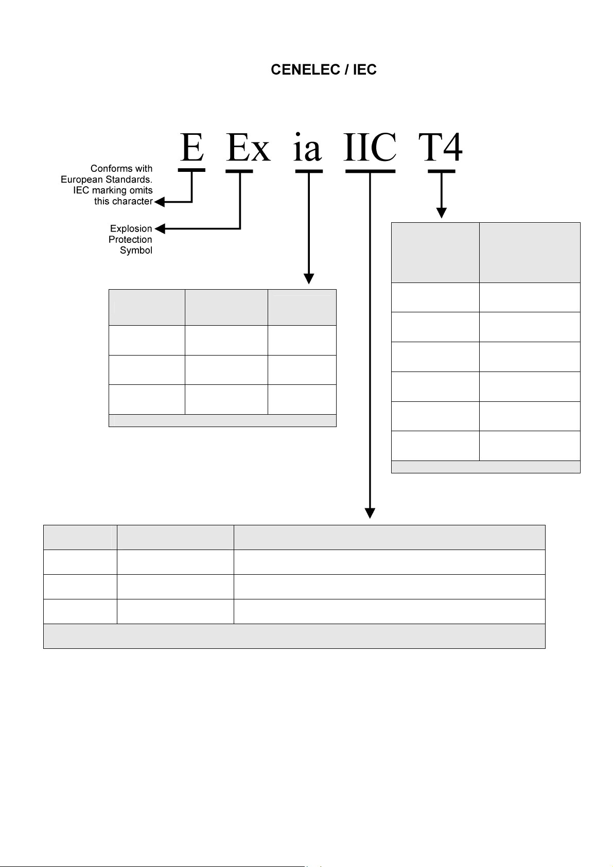
Temperature
Code
Type of
Protection
Code
Equipment
Category
Class
Referred to
ambient of
-20°C to +40°C
T6 85°C
T5 100°C
Maximum Surface
Temperature
ia Intrinsic safety 1
ib Intrinsic safety 2
d Flameproof 3
These Flame Detectors are approved ia.
Table 2 – Type of Protecti on Codes
Gas Group Representative Gas Other Gases, Liquids & Vapours
IIC
IIB
IIA
Hydrogen Acetylene, Car bon Disulphide
Ethylene Diethyl ether, Tetrafluroethylene
Methane Butane, Met hanol, Petroleum, Propane, Styrene
These Flame Detectors are approved IIC for listed gases in EN 50014.
T4 135°C
T3 200°C
T2 300°C
T1 450°C
Detectors approved to T4 at 40°C
Table 3 – Temperat ur e Classif ic ations
2-3-0-809/ISS2/JUL07
Table 4 – Subdivisions of Group II Gases
Page 5

Hochiki Europe ( UK ) Ltd 5
y
Intrinsically Safe Product
Technical Data
Mechanical
Fig. 1
Intrinsically Safe Flame Detector
(Alloy Housing)
The flame detector s respond to light
emitted from flames during combustion.
The detectors discriminate between fl am es
and other light sourc es by respondi ng only
to low frequency flickering produced by
flames (ty pic ally 1 to 15Hz) . The detectors
ignore fixed light sources and rapidly
flickering illumination predominantly
produced by lighting.
The flame flicker techniques have the
advantage of still allowing the detection of
flames through a thin layer of oil, water
vapour, ice or dust. This makes these
detectors particularly usef ul in industr ial
applications.
Full details of the princ iples of operation,
electric al description, and other det ailed
technical data are published in the products
individual dat a sheet .
Housing Materi al:
See Fig 1
Housing Colour: Blue (typical)
Housing
Dimension:
(Excluding M ount)
Cable Gland
Entries:
Die Cast Zinc Alloy
Height = 142mm
Width = 108mm
Depth = 82mm
2 X 20mm
Electrical
Supply In:
Voltage
Current
Polarity sensitive
Optional Input:
Voltage
Current
Polarity sensitive
Optional Output:
Voltage
Current
Optional Relays
Contact Ratings:
Voltage
Current
Resistive Loads Onl
Terminals 1(+ ) & 2( -)
14 to 30Vdc
2 to 30mA See datasheet for detail
Terminals 3(+ ) & 4( -)
14 to 30Vdc
40µA typ. @ 24V IN
Terminals 3(+ ) & 4( -)
0V to Supply In (O/C)
2.4mA typ. Inter nally Limi ted
Terminals 3 to 8
30Vdc. Max.
1 Amp. Max.
Environmental
Operating Ambient
Temperature:
Check detector
limits
ATEX
Approval Category
CENELEC / IEC
Marking
Apparatus
Certific ate Number BAS02ATEX1001
-20°C to +40°C(T 4)
-20°C to +85°C(T 3)
II 1 G
EEx ia IIC T4
2-3-0-809/ISS2/JUL07
Page 6

6 Hochiki Europe ( UK ) Ltd
System Design
Engineers f amili ar with codes of practice for hazardous area systems should only under take the design of
an intrinsic ally safe fire detecti on system. In Europe the standard is EN 50014, El ectri c al appar atus for
potentially explosive atmospheres – General requirements.
The fire detector performance is the same as the standard none intrinsically safe counterparts.
Performance information given in standard pr oduc t guides is theref or e appl icable to the intrinsi c ally safe
range.
The BASEEFA certification of the intrinsically devices covers their characteristics as components of an
intrinsic ally safe system. This indicates that the flame detector s can be used with a margin of safety in
such syst e ms.
In safe area (standard) applications it is some times desirable t o connect the wiring as a loop, with both
ends terminated at the control panel. In the ev ent of an open-cir c uit fault it is then possible to drive both
ends simult aneousl y . In a hazardous area it is not possible t o use a loop confi gur ation because the
potential t o feed power from each end of the loop would double t he av ailable energy in the hazardous
area and contravene the energy limitations of the intrinsically safe certification. All circuits must therefor e
be connected as spars fr om the safe area or as radial connections from the control panel.
Types of Safety Barrier
The system confi gur ation can for three types of saf ety barrier, each of which has its own advantages and
disadvantages. A bri ef outline of the characteristics is given below.
Single Channel 28V/300Ω Barrier
This is the most basic t y pe of barrier and therefore the lowest cost. B eing passive devices, they also
impose the minimum of restrictions on the operation of the flame detectors. Thus, single channel barrier s
are availabl e either as positive or negativ e polar ity where the polarity r efers to the polarity of the applied
voltage relative to earth. The significance of this is that one side of the barrier must be connected t o a
high-integrity ( s afety) earth. Although this connection has no eff ect on the operation of the flame det ector
and is not needed for t heir correc t operation, it may not be accept able to the operation of the contr ol and
indicating equipment. This is particularly true if the control equipment incorporates earth-leakage
monitoring and ev en without this featur e the earthing of the loop may cause unwanted cross-talk between
loops.
If the earth connec tion is not acceptable then the A.C. or isolating barrier s should be used.
Star-connected A.C. Barrier
A.C. barrier s are also passive devices and must still be connected to a high-int egri ty safety earth.
However, they ar e desi gned to allow either positiv e or negative voltages with respect to ear th and under
normal conditi ons provide a connection t o earth v ia a reverse-diode, rather than dir ec tly.
The disadvantage of this type of barrier is that the end-to- end r esi stanc e is nominally 1200ohms
compared wit h the 300 ohms of the single channel type. This high resi stanc e r esul ts in an extra voltage
drop in the circuit . Thi s ty pe of barrier is not recommended f or general use
Galvanically Isolated Barrier
Galvanically isolated barri er s (also know as transformer isolat ed bar ri er s) dif fer from conventi onal shunt
zener barrier s i n that they pr ov ide electrical isolat ion between the input (safe area) and the output
(hazardous area). This is achieved by the use of a D.C./D.C. converter on the input si de, which is
connected to t he haz ar dous area t hr ough a v oltage and power limiti ng r esistor/zener com bination similar
to a conventional barrier.
The galvanic isolation technique means that the circuit does not need a high integrity (safety) earth and
that the intrinsically safe circuit is fully floating. Earth leakage problems for control and indicating
equipment are therefore eliminated if this type of interface is used.
2-3-0-809/ISS2/JUL07
Page 7

Hochiki Europe ( UK ) Ltd 7
Galvanically isolated barri er s are widely used with conventional flame detector system s. If the system is
of an addressable ty pe with signal pulses on the supply li nes then the response time of most standard
barriers will be too slow to allow their use. In these applications special galv anic ally isolated barri ers are
required that can freely transmit the requir ed pr otocol pulses without introducing sever e voltage dr ops.
These interf ac es are available as single or dual channel versions and are recomm ended for any
application in which direct earth connec tions are not acceptable.
The galvanically isolated barri er i s a two-wire device which does not need an exter nal power supply.
Current drawn fr om the detector supply connecti ons by t he bar ri er itself is less than 500µA
Approved Safety Barriers
For systems a generi c specification for the barriers is as follows:
Any shunt zener diode safety barrier certif ied and approved to meet the ATEX Dir ectiv es or CENE LE C /
IEC standards.
ATEX group and category
CENELEC / IEC marking [EEx ia] II C (associated apparatus)
Having the followi ng or lower output parameters:
Max. output volts U
Max. output curr ent I
Max. output power P
A number of barrier s meet this speci fication and ex am ples are given below:
: = 30V
o
: = 100mA
o
: = 0.65W
o
II (1) G
Supplier Type Polarity Mounting Technique
Pepperl & Fuchs Ltd
77 Ripponden Road
Oldham
Lancashire O L2 8PF
United Kingdom
www.pepperl-fuchs.com
MTL
Power Court
Luton
Bedfordshi r e LU1 3J J
United Lingdom
www.mtl-inst.com
Z728
Z779
Z828
KFD0-CS-Ex1.51
KFD0-CS-Ex2.51
MTL7028+
MTL7728+
MTL7779+
MTL7706+
+
+
-
+
+
+
+
DIN rail
DIN rail
DIN rail
DIN rail
DIN rail
DIN rail
DIN rail
DIN rail
DIN rail
Shunt 300Ω
Shunt 300Ω X 2
Shunt 300Ω
Galvanic X 1
Galvanic X 2
Shunt 300Ω
Shunt 300Ω
Shunt 300Ω X 2
Active 300Ω,
4-20mA output
Safety Earth
Single channel and st ar c onnec ted A.C. safety barriers must be connected to a high integrity earth by at
least one and preferably two copper cables, each of cross sectional area of 4mm² or greater. The
connection m ust be such t hat t he im pedanc e from the connection point to the main power system earth is
less than one ohm.
Intrinsically safe circuit s in the haz ar dous area shoul d be insulated fr om eart h and must be capable of
withstanding a 500V RMS A.C. test voltage for at least one minut e.
When using armoured or c opper sheathed c ables, the armour or sheath is normally isolat ed from the safe
area busbar.
2-3-0-809/ISS2/JUL07
Page 8

8 Hochiki Europe ( UK ) Ltd
Wiring and Cable Types
It is not permitted to connect more than one barrier ci r cui t in the hazardous area to any other ci r cuit.
Both separate and twin cables may be used. A pair contained in a type ‘A’ or ‘B’ m ulticor e cable (as
defined in clause 5.3 of E N50 039) m ay also be used, provided that the peak volt age of any ci r c uit
contained wit hin the multicore does not exc eed 60V.
The capacitance and either inductance or the inductance to resistance ( L/R) ratio of the hazardous area
cable must not exceed t he par am eters specified in Table 6. The reason for this is that energy can stored
in a cable and it is necessary to use cable in which energy stored is i nsufficient to ignit e an expl osive
atmosphere.
To calculate t he tot al c apaci tance or inductance for the length of cable in the hazardous area, refer to
Table 7, which gives typical per kilometre capacitance and inductance for commonly used cables.
Note: The fl ame detector s have zero equivalent inductance (Li = 0) and a 0.03μF capacitance ( Ci =
0.03μF).
Gas group IIA IIB IIC
Capacitance μF
Inductance mH
L/R ratio μH/ohm
Table 6 – 28V Barrier, Maximum Permissible Stored Energy in Cables
Cable Type Core
MICC Pyrtenax
light duty
MICC Pyrotenex
heavy duty
Pirelli FP200
PVC sheathed and
Insulated to B S 6004
Table 7 Examples of el ectri c al c har acteristic s of cabl es comm only used in fire protection system s
2.15
33.6
440
2
2
all
all
Size
mm²
1.5
1.5
1.5
1.5
0.65
12.6
165
Conductor
resistance
ohm/km/core
12.1
12.1
12.1
12.1
0.083
4.2
55
Inductance
mH/km
0.534
0.643
0.77
Capacitance µF/km
core
to
core
0.19
0.13
0.08
0.09
core
to
sheath
0.21
0.17
0.15
Sheath
Resistance
ohm/km
2.77
1.58
Maximum Loading of IS Circuit
Because of the finite resistance of the safety bar ri er, there will be a limit to the current drain which can be
tolerated before the voltage on the circuit falls outside the specified limits for the IS detector . The standing
current for the detectors can be calculat ed by the sum of t he indiv idual selected det ector c ur r ents as
given in the detect or data sheet. This may limit the maxim um number of detectors per barri er t o two or
three.
2-3-0-809/ISS2/JUL07
Page 9

Hochiki Europe ( UK ) Ltd 9
Installation
It is important that the I S detec tors are installed in such a way that all t erminals and connections are
protected t o at least I P 20 with the detector cover fitted. The earth bonding terminals are provided for
convenienc e where continuity of a cable sheath or similar is required
Service & Repairs
Servicing of I S flam e detectors may be carried out onl y by a BASEEFA or equivalent authorised body. In
practic al term s this means that IS flame detector m ay be servi c ed only at the manufactures factory.
Servicing of t he fire pr otection system should be car ri ed out as recommended by the local r egulation in
force.
2-3-0-809/ISS2/JUL07
Page 10

10 Hochiki Europe ( UK ) Ltd
IS System Drawing
NOTE 1
Each Barrier fed circuit must be a separate circui t and must not
be conn ect ed w it h an y ot h er electrical circu it .
NOTE 2
The electrical circuit in the hazardous area must be capable of
withst an di ng an AC t est voltag e of 50 0 vol t s RMS to ear t h or
frame of th e ap p aratus for on e min ute.
NOTE 3
Detector Input P ar am eters
Terminal 1 with res p ect to te rminal 2
Terminal 3 with res p ect to te rminal 4
Ui = 30V
Ii = 100mA
Pi = 0.65W
Ci = 0.03µF
Li = 0
Terminal 5 with res p ect to te rminal 6
Terminal 7 with res p ect to te rminal 8
Ui = 30V
Ii = 100mA
The inst all at i on m us t c omply with n at i on al ins tallat i on
requirem ents (f or ex am pl e t o EN 600 7 9- 1 4)
NOTE 4
The capac it ance and either the ind uc tanc e or the ind uc tanc e to
resist ance (L/R) r atio of the haz ard ous area cabl es mus t n ot
exceed the maximum permissible parameters for the required
groups IIA , IIB an d IIC .
NOTE 5
The cable may be separate cables or a twin pair contained in a
type ‘A’ or a t yp e ‘B’ mul t icore cabl e (as def i n ed in cl ause 5.3 of
EN50 039). Provided that the peak voltage of any circuit
contain ed wi thi n t h e mut icore do es n ot exceed 60 vol ts .
NOTE 6
If requir ed a l oad in g r es is t or of n ot les s th an 3k 0.5 w att an d
having a surface area between 20cm² and 10cm² may be
connected betw e en th e t er mi nals of any ci rc uit, but not b et we en
circuits.
2-3-0-809/ISS2/JUL07
Page 11

Hochiki Europe ( UK ) Ltd 11
Hochiki Europe (UK) Ltd
Grosvenor Road, Gillingham Bus ine ss Park,
Gillingham, Kent, ME8 0SA, England
Telephone: +44(0)1634 260133 Facsimile: +44(0)1634 260132
Email: sales@hochikieurope.co m
Web: www.hochiki europe.com
Hochiki Europe (UK) Ltd. reserves the right to alter the specification of its products from time to time without notice. Although eve ry effo r t
has been made to ensure the accuracy of the information contained within this document it is not warranted or represented by Hochiki
Europe (UK) Ltd. to be a complete and up-to-date description. Please check our web site for the latest version of this document.
2-3-0-809/ISS2/JUL07
 Loading...