

Page 1

IFD-E(Exd)
Explosion-Proof Flame Detector
User Manual
Page 2

2 Hochiki Europe (UK) Ltd
General
Description
This Installation Guide gives information on the Flameproof (EExd) version of the flame detectors that
have been approved by ISSeP (Institut Scientifique de Service Public; notified body number:492). The
requirements of the European Community Directive 94/9/EC, the ATmosphere EXplosives ATEX
Directive have been met. The approval has been assessed by reference to the following standards,
EN50014:1997+A1 and A2:1999, EN 50018:2000 and pr AA EN 50018 plus a review again st EN60 0791:2004 which showed that there were no changes which materially affected the “state of technological
progress” with respect to the product. EN50281-1-1:1998.
The detector enclosure is certified
The detector is triple infra-red (IR³) and the housing is copper-free aluminium alloy (LM25).
The guide also provides information on Flameproof (type‘d’) enclosures, the application, maintenance,
installation and adjustments of the detectors. Reference to other individual detector publications can be
made available for more information on none Flameproof issues. These publications are available on
request.
NOTE: Information in this guide is given in good faith, but the manufacturer cannot be held responsible
for any omissions or errors. The company reserves the right to change the specifications of
products at any time and without prior notice.
II 1 G EEx ia IIC T4 and can be used with all listed gases.
Introduction to Flameproof Enclosures
There are many places where an explosive mixture of air and gas or vapour is or may be present,
intermittently or as a result of an accident. These are defined as hazardous areas by EN 60079-0
(formally EN 50014), Electrical apparatus for explosive gas atmospheres – General requirements.
Hazardous areas are common in petroleum and chemical engineering plants and in factories processing
and storing gases, solvents, paints and other volatile substances.
Electrical equipment for use in these areas needs to be designed so that it cannot ignite an explosive
mixture, not only in normal operation but also in fault conditions. There are a number of methods
available to achieve this – oil immersion, pressurised apparatus and powder filling, for example, but the
two most common used are intrinsic safety and flameproof enclosures.
Flameproof equipment is contained in a box so strong that an internal explosion will neither damage the
box nor be transmitted outside the box. The surface must remain cool enough not to ignite the explosive
mixture.
When flameproof equipment is interconnected, flameproof wiring must be used. This method is most
valuable when high power levels are unavoidable but it is not acceptable for areas in which an explosive
gas/air mixture may be continuously present or present for long periods.
For this reason these flame detectors are made intrinsically safe rather than flameproof. Intrinsically safe
equipment operates at such low power and with such small amounts of stored energy that it is incapable
of causing ignition:
In normal conditions
With a single fault (for ib type of protection code)
With any combination of two faults (for ia type of protection code)
In any of these conditions every component must remain cool enough not to ignite gases for which it is
approved. See Table 4
2-3-0-810/ISS3/OCT11
Page 3

Hochiki Europe (UK) Ltd 3
Classification of Hazardous Areas
EN 60079-0 (formally EN50014) states that electrical apparatus for potentially explosive atmospheres is
divided into:
Group I: Electrical apparatus for mines susceptible to fire damp;
Group II: Electrical apparatus for places with a potentially explosive atmosphere, other than
mines susceptible to fire damp.
These flame detectors are designed to meet the requirements of Group II apparatus. For the type of
protection “d” Flameproof, Group II is subdivided into Equipment Categories, Type of Explosive
Atmosphere (Table 1), Type of Protection Code (Table 2), Temperature Class (Table 3) and Gas Group
(Table 4).
2-3-0-810/ISS3/OCT11
Page 4

4 Hochiki Europe (UK) Ltd
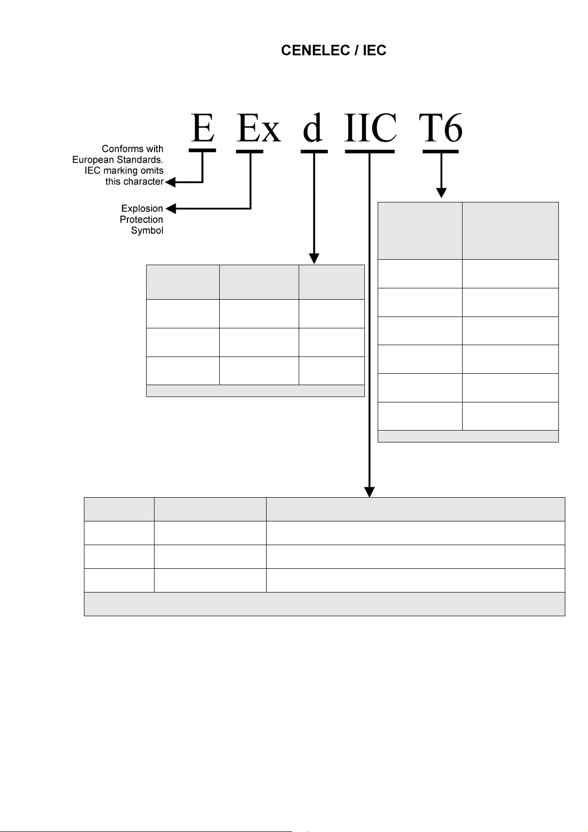
Equipment Markings
Type of Explosive
Atmosphere Group II
Equipment
Category
Definition
G - gas vapour mist
D - dust
Zone
1 - very high level of protection
in which explosive atmosphere mixtures of
0
air gases, vapours or mist are present
continuously, for long periods
2 - high level of protection
in which explosive atmosphere mixture of
1
air and gases, vapours or mist are likely to
occur
3 - normal level of protection
in which explosive atmosphere mixtures of
air and gases, vapours or mist are unlikely
2
to occur and if it occurs it will exist only for a
short period
These Flame Detectors are suitable for equipment categories 2 and 3, G or D.
Note: The detectors are not certified for category 1 areas, see ‘IS’ products.
Table 1Equipment Categories and Type of Explosive Atmosphere (Group II)
2-3-0-810/ISS3/OCT11
Page 5
Hochiki Europe (UK) Ltd 5
Temperature
Class
Referred to
ambient of
Maximum Surface
Temperature
-20°C to +40°C
T6 85°C
T5 100°C
Code
Type of
Protection
Code
Equipment
Category
ia Intrinsic safety 1
T4 135°C
ib Intrinsic safety 2
T3 200°C
d Flameproof 3
T2 300°C
These Flame Detectors are approved ia.
Table 2 – Type of Protection Codes
T1 450°C
Detectors approved to T4 at 40°C
Table 3 – Temperature Classifications
Gas Group Representative Gas Other Gases, Liquids & Vapours
IIC
IIB
IIA
Hydrogen Acetylene, Carbon Disulphide
Ethylene Diethyl ether, Tetrafluroethylene
Methane Butane, Methanol, Petroleum, Propane, Styrene
These Flame Detectors are approved IIC for listed gases in EN 50014.
Table 4 – Subdivisions of Group II Gases
2-3-0-810/ISS3/OCT11
Page 6

6 Hochiki Europe (UK) Ltd
Flameproof Safe Products
Technical Data
Mechanical
Housing Material:
See Fig 1
Housing Colour: Red
Housing
Dimension:
(Excluding Mount)
Weight 2.5kg
Cable Gland
Entries:
Fig. 1
Flameproof Flame Detector
(Alloy Housing)
Power Up Time: 2 Seconds
The flame detectors respond to light emitted from
flames during combustion.
The detectors discriminate between flames and
other light sources by responding only to low
frequency flickering produced by flames (typically
1 to 15Hz). The detectors ignore fixed light
sources and rapidly flickering illumination
predominantly produced by lighting.
The flame flicker techniques have the advantage
of still allowing the detection of flames through a
thin layer of oil, water vapour, ice or dust. This
makes these detectors particularly useful in
industrial applications.
Full details of the principles of operation,
electrical description, and other detailed technical
data are published in the products individual data
sheet.
Electrical
Supply In:
Voltage
Current
Polarity sensitive
Optional Input:
Voltage
Current
Polarity sensitive
Relays
Contact Ratings:
Voltage
Current
Power
Environmental
Operating
Ambient
Temperature:
ATEX
Approval Category
CENELEC / IEC
Marking
Apparatus
Certificate
Number
IP Rating IP66
Copper Free Aluminium Alloy LM25
Height = 150mm
Width = 146mm
Depth = 137mm
3 X 20mm
Terminals 1(+) & 2(-)
14 to 30Vdc
2 to 28mA See datasheet for detail
Terminals 3(+) & 4(-)
14 to 30Vdc
40µA typ. @ 24V IN
Terminals 5 to 8
50Vdc max
1A max
30W max
-10°C to +40°C(T4)
-10°C to +55°C(Sensor limit)
II 2 G D
EEx d IIC T6 (85°C)
- Zone 1, 21, 2 and 22
ISSeP 03ATEX012
2-3-0-810/ISS3/OCT11
Page 7

Hochiki Europe (UK) Ltd 7
System Design
Engineers familiar with codes of practice for hazardous area systems should only undertake the design of
an flameproof fire detection system. In Europe the standard is EN 60079-0 (formally EN 50014), Electrical
apparatus for potentially explosive atmospheres – General requirements.
The fire detector performance is the same as the standard none flameproof counterparts. Performance
information given in standard product guides is therefore applicable to the flameproof range.
The ISSeP certification of the flameproof device enclosure covers their characteristics as components of
a flameproof system. This indicates that the flame detectors can be used with a margin of safety in such
systems.
Service & Repairs
Frequent inspection should be made. A schedule for the maintenance check should be determined by the
environment and frequency of use but should be regular enough to ensure the detector continu es to
operate in the designed manner. It is recommended that it should be at least once a year.
1. External surfaces of the enclosure should be periodically cleaned to ensure dust deposits are not
allowed to accumulate.
2. Check flamepath/threads on enclosure body and lid for signs of corrosion. If badly pitted, replace
component.
3. All components that are replaced must be in accordance with the manufactures specification.
Failure to use such components may invalidate the certication/approval on the enclosure and
may make the enclosure dangerous.
4. After inspection and maintenance have been carried out, items 3 & 4 of the installation
instructions should be adhered to when resealing the enclosure.
5. Servicing of the fire protection system should be carried out as recommended by the local
regulation in force.
Selection of Cable Glands
Application of barrier glands certified and approved to meet EN 60079-14 for Thermo Plastic,
Thermosetting and Elastomeric Cables.
Hazardous Area Type Gland Method
1)
2)
Table 5 Examples of barrier glands
Zone 1, 2 21 & 22 Hazardous areas
requiring IIC apparatus
Zone 2 & 22 Hazardous areas requiring IIA
& IIB apparatus.
EExd Barrier Glands
mandatory
Any EExd Gland
permitted
2-3-0-810/ISS3/OCT11
Page 8

8 Hochiki Europe (UK) Ltd
Enclosure Details
Health and Safety at Work Act
In the UK all equipment must be installed and disposed of (as required) within the legislative requirements
of the Health & Safety at Work Act 1974.
Installation
No modification should be made to the enclosure without reference to the manufacturer as unauthorised
modification to an approved enclosure will invalidate the certificate/approval
1. The enclosures are supplied with drilled and tapped entries. See enclosu re d rawing
2. The surface of the machined/threaded flame paths between cover and body must be prote cted
from scratches or damage during installation. Any such damage can destroy the validity of the
enclosure.
3. Before the cover is refitted, the flame path/threaded joint between cover and body must be
thoroughly wiped clean of dirt, grit or other foreign substances, and then a thin coating of an
approved form of non-setting grease applied to joint/threads. Ensure the gasket o-ring is free
from damage.
4. Threaded covers must be screwed on to a minimum of 5 full threads of engagement and then
locked in poison with the locking screw provided.
5. All tapped entries must be fitted with an approved flameproof (EExd) device which is equivalent
or superior to the gas group of the enclosure.
6. The enclosure should be mounted using the two rear M6 tapped holes.
7. Do not scratch the glass.
8. Glanding of cables should be as in Selection of Cable Gland section
2-3-0-810/ISS3/OCT11
Page 9

Hochiki Europe (UK) Ltd 9
Enclosure with Front Cover Removed
2-3-0-810/ISS3/OCT11
Page 10

10 Hochiki Europe (UK) Ltd
EExd System Drawing
NOTE 1
WARNING – Ensure ALL power is OFF before/during
installation/maintenance.
NOTE 2
Ensure the details on the enclosure label comply with the
hazardous area specified.
NOTE 3
The installation must comply with national installation
requirements (for example to EN 60079-14)
NOTE 4
If required a loading resistor or end of line device (EOL) can be
connected between the detector terminals of any circuit. The total
power dissipation and temperature classes within the enclosure
must not be exceeded, 30W – T6.
NOTE 5
If required a loading resistor of not less than 3k 0.5 watt and
having a surface area between 20cm² and 10cm² may be
connected between the terminals of any circuit, but not between
circuits.
2-3-0-810/ISS3/OCT11
Page 11

Hochiki Europe (UK) Ltd 11
Hochiki CHQ Module Connection Information
Fig 10 Connection Diagram using a CHQ-SZM Single Zone Monitor (or CHQ-MZ)
2-3-0-810/ISS3/OCT11
Page 12

12 Hochiki Europe (UK) Ltd
Fig 11 Connection Diagram using a CHQ-DIM Dual Input Module (or CHQ-S)
2-3-0-810/ISS3/OCT11
Page 13

Hochiki Europe (UK) Ltd 13
Fig 12 Connection Diagram using a CHQ-POM Powered Output Module
NOTE: The CHQ-POM has a variable output, this should be set at 30mA.
2-3-0-810/ISS3/OCT11
Page 14

14 Hochiki Europe (UK) Ltd
Fig 13 Connection Diagram using a CHQ-DZM Dual Zone Monitor (or CHQ-Z)
2-3-0-810/ISS3/OCT11
Page 15

Hochiki Europe (UK) Ltd 15
Hochiki Europe (UK) Ltd
Grosvenor Road, Gillingham Business Park,
Gillingham, Kent, ME8 0SA, England
Telephone: +44(0)1634 260133 Facsimile: +44(0)1634 260132
Email: sales@hochikieurope.com
Web: www.hochikieurope.com
Hochiki Europe (UK) Ltd. reserves the right to alter the specification of its products from time to time without notice. Although every effort
has been made to ensure the accuracy of the information contained within this document it is not warranted or represented by Hochiki
Europe (UK) Ltd. to be a complete and up-to-date description. Please check our web site for the latest version of this document.
2-3-0-810/ISS3/OCT11
 Loading...