

Page 1
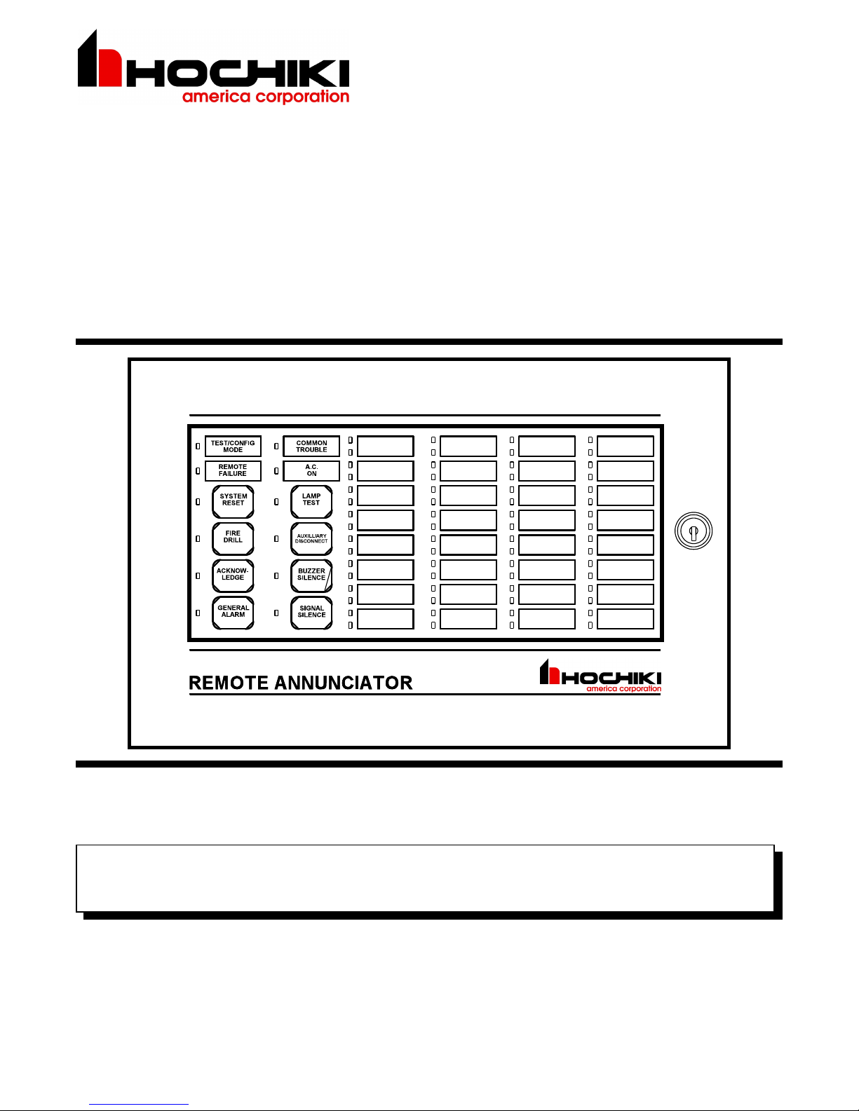
HRA-1000 SERIES
Remote Multiplex Annunciator Panels
WIRING and INSTALLATION INSTRUCTION
L NOTICE
All information, documentation, and specifications contained in this manual are subject to change without prior
notice by the manufacturer.
©2002 by Hochiki America Corporated
Printed May 2002
LT-617 HO C R ev.3
Page 2
INTRODUCTION
Hochiki modular design HRA-1000 Series Remote Multiplex Annunciator panels provides a large capacity of annunciation (up
to 224 points) with standard Hochiki Series 1000 Fire Alarm Control Panels. The HRAM-1032 Main Annunciator Chassis is a
32 Circuit, Annunciator which may be expanded with up to four HRAX-1048 Adder Annunciator Chassis to a maximum of 224
Circuit Display Points. Each Circuit Indicator is a bi-color LED that is automatically configured to match the Fire Alarm Control
Panel configuration. There are five types of enclosures available: the HBB-1001, HBB-1002 and HBB-1003 which can take 1,2,3
chassis resp ectively.
INSTALLATION INSTRUCTION
Note that the HRAM-1032 is supplied with the NP-680 Laser Printable Label Sheet. Column 1A or 1B (English or
French) is selected for 2-Stage or 1-Stage Systems respectively. Column 3 is discarded and the last four colum ns are
filled with the blanks after they have been printed. The HRAX-1048 is supplied with the NP-681 Blank Las er Printable
Label Sheet.
NOTE: The HRA-1000 normally displays Initiating Circuit Status (no individual circuit troubles) only. Indicating and
Relay Circuits are not remotely displayed. See the Fire Alarm Control Panel Manual for more details.
2
Page 3

WIRING INSTRUCTION
The RS-485 Wiring to the RAM-1032 Module
needs to be Twisted Shielded Pair as shown in the
diagram. The wire gauge may be ...
22 AWG up to 2000 ft.
20 AWG up to 4000 ft.
18 AWG up to 8000 ft.
The RS-485 wiring from the Fire Alarm Control
Panel to the Annunciator(s) must be point-to-point
from the FA Panel to the first Annunciator, then the
next Annunciator, and so on. No star-wiring or T-
tapping is allowed.
Each HRAM-1032 Annunciator Module has a 120
ohm End-of-Line Resistor onboard for
termination (via JW6) of the RS-485. This JW6
jumper is removed on all except the last wired
Module.
The 24 VDC field wiring needs to be of an
appropriate gauge for the number of annunciators
and the total wiring run length. See the
Specifications section “Current Drain for Battery
Calculations”, and calculate the Maximum current
for all Annunciators summed together ...
NOTE: Accidentally connecting any of the 24 VDC wires to the RS-485 wiring could result in damage to the HRAM-
1032/16 and/or to the Fire Alarm Control Panel that it is connected to !!!
Maximum for
all Annunciators
Amperes ft m ft m ft m ft m Ohms
0.06 2350 716 3750 1143 6000 1829 8500 2591 30
0.12 1180 360 1850 567 3000 915 4250 1296 15
0.30 470 143 750 229 1200 366 1900 579 6
0.60 235 71 375 114 600 183 850 259 3
0.90 156 47 250 76 400 122 570 174 2
1.20 118 36 185 56 300 91 425 129 1.5
1.50 94 29 150 46 240 73 343 105 1.2
1.70 78 24 125 38 200 61 285 87 1.0
MAXIMUM WIRING RUN TO LAST ANNUNCIATOR MAX. LOOP
18AWG 16AWG 14AWG 12AWG
RESISTANCE
3
Page 4

DIP SWITCH SETTINGS & CABLING
Each Annunciator Asse m bly (M ain and Add er Chassis ’) ne eds to be assigned a unique, s equential “Address” via the
Main Chass is DIP Switch S W 1. DIP Switch SW 2 is used to allow disabling of some Front Panel push buttons (when
individual sw itches are “ON” then the correspon ding push bu tton is disabled).
The H RAM-103 2 DIP Switch es are set as ...
SW1-1 = Address A0 SW2-1 = Disable System Reset Button
SW1-2 = Address A1 SW2-2 = Disable Fire Drill Button
SW1-3 = Address A2 SW2-3 = Disable Acknowledge Button
SW1-4 = Address A3 SW2-4 = Disable General Alarm Button
SW1-5 = Not Used SW2-5 = Not Used
SW1-6 = Not Used SW2-6 = Disable Auxiliary Disconnect Button
SW1-7 = Not Used SW2-7 = Not Used
SW1-8 = Not Used SW2-8 = Disable Signal Silence Button
The An nun ciator “Addres s” (see the Manual for the Fire Alarm Control Pane l being used), is se t as ...
DIP Switch Positions
1 2 3 4 5 6 7 8 9 10 11 12 13 14 15
SW1-1 (A0) on off on off on off on off on off on off on off on
SW1-2 (A1) off on on off off on on off off on on off off on on
SW1-3 (A2) off off off on on on on off off off off on on on on
SW1-4 (A3) off off off off off off off on on on on on on on on
Annunciators on a common RS-485 connection must
be numbered sequentially; i.e.: 1,2,3,4, and not
randomly suc h as 5,3,8,14 !! Note that not all
Annunciator “Addresses” are valid fo r all Fire Alarm
Control Panels. Refer to the Fire Alarm Control Panel
Manual for further information.
On the HRAX-1 048 Adder Annunciato r Chassis ...
P1 - Connects to the Main An nunciator
Chassis, or to the previous Adder
Annunciator Chassis.
P2 - Connects to the next Adde r
Annunciator Chassis.
Annunciator “Address”
On the HRAM -103 2 M ain An nunciator Chassis ...
P2 - Connects to the first Adder
Annunciator Chassis.
P3,P11 - Not Used.
Jumpers - Fa ctory Set, do not change.
Terminals - As described under Wiring.
SW1, SW2 - DIP Switches as described above.
JW6 - RS-485 Termination jumper, remove
on all except the last HRAM -1032 used.
4
Page 5

SPECIFICATIONS & FEATURES
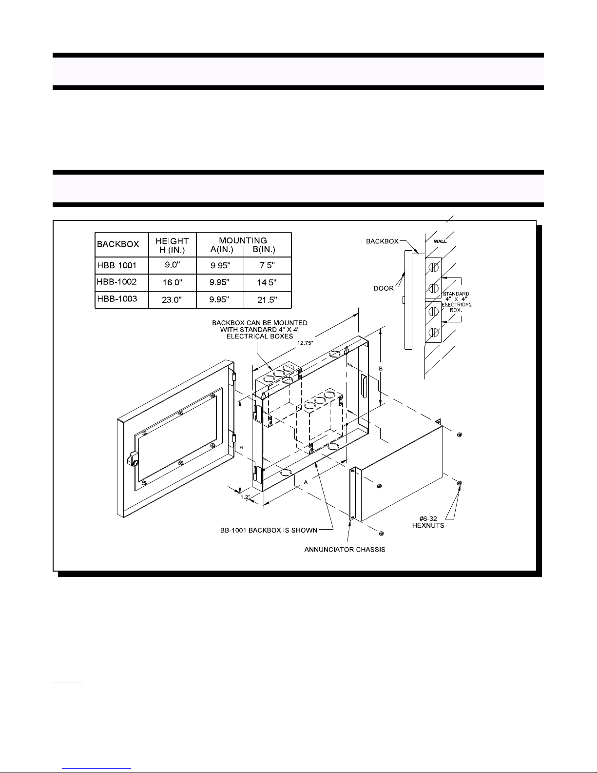
Enclosure Models:
HBB-1001 Backbox for one Annunciator Chassis with keylock door.
HBB-1002 Backbox for up to two Annunciator Chassis with keylock door.
HBB-1003 Backbox for up to three Annunciator Chassis with keylock door.
Notes: 1. Enclosure finish: Painted semi-gloss off white
2. Material: HBB-1001, HBB-1002, HBB-1003 are 18 GA. (0.048") thick CRS
except the HBB-1003 Door which is 16 GA (0.060”).
3. See installation instruction section for enclosure's dimensions.
Module Models:
HRAM-1032 MAIN ANNUNCIATOR CHASSIS (32 Display Points)
20 to 31 VDC (filtered or full-wave-rectified)
Sealed membrane-like buttons and LED indicators.
Local Buzzer, Indicators (AC-On, Common Trouble, Remote Failure, Aux. Disconnect, Acknowledge, General
Alarm, Signal Silence, Test/Config Mode), and Controls (System Reset, Lamp Test, Fire Drill, Aux. Disconnect,
Buzzer Silence, Signal Silence, General Alarm, Acknowledge).
Buzzer Silence activation silences the main fire alarm panel buzzer and all attached annunciator buzzers.
Annunciation of up to 32 Points.
Expandable by using up to four HRAX Modules.
Standb y: 50 mA Max., A ll LED’s “On”: 150 mA Max.
HRAX-1048 ADDER ANNUNCIATOR CHASSIS (48 Display Points)
Interconnect via one ribbon cable to HRAM-1032 or to previous HRAX-1048.
Annunciation of up to 48 additional Points.
Standb y: 15 mA Max., A ll LED’s “On”: 100 mA Max.
Current Drain for Battery Calculations:
The maximum normal current drain will be during Lamp Test when all lamps are illuminated on one chassis at a
time. Thus the currents are ...
Normal Standby = 50 mA + ______________ X 15 mA = _________
Maximum = 150 mA + ______________ X 15 mA = _________
The Normal Standby Current is used for Battery Size Calculations (see the Fire Alarm Control Panel manual) and
includes the current drain for the Trouble Buzzer, Trouble LED, and one Alarm LED. The Maximum Current is used
to calculate the wire size (see the Wiring Instruction).
(number of Adder Chassis)
(number of Adder Chassis)
5
Page 6

WARRANTY
Hochiki America Corporation, man ufactur ed equip m ent is guaranteed to b e free of def ects in mate rial and
workm anship for a per iod of o ne (1) year from the date of original shipm ent. H OC HIK I will repair or replace, at its
option, any equipment which it determines to contain defective material or workmanship. Said equipment must be
shipped to HOCHIKI prepaid. Return freight will be prepaid by HOCHIKI. W e shall not be responsible to repair or
replace equipment which has been repaired by others, abused, improperly installed, altered or otherwise misused or
damaged in any way. Unless previously contracted by HOCHIKI, HOCHIKI will assume no responsibility for
determining the defective or operative status at the point of installation, and will accept no liability beyond th e re pair
or replacem ent of the produ ct at our factory authorized s ervice departm ent.
Hochiki America Corp.
7051 Village Drive
Buena Park, CA
USA 90621
Phone:(714) 522-2246
FAX:(714) 522-2268
Technical Support Phone: 1-800-845-6692
or technical support @hochiki.com
6
 Loading...