

Page 1
HOCHIKI ADDRESSABLE CALL POINT
INSTALLATION INSTRUCTIONS
Products co vered: HCP-W, HCP-W(DPS) , HCP-W( SCI) & HCP-WM
IMPORTANT: These call poi nts are suitable for use only wit h the particular class of system f or which t hey ar e
intended. These units are only compatibl e with t he Enhanced Systems Protocol (ESP). All units are weatherproof
and can be installed externally. Important Note – The use of lubricants, cleaning solvents or petroleum
based products should be avoided.
SETTING THE ESP LOOP ADDRESS
Ensure that each device has a unique address set before operation. Note the address can be set before or after
connection to the loop but the loop MUST NOT be powered. The address is set by connecting a hand held
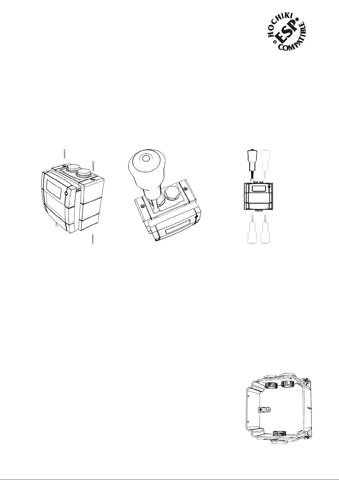
programmer (T CH- B 100) to the progr amming connector inside the unit. To access this, first remov e the f our cover
screws located at t he top and bot tom of the unit (see fig 1). Place the blade of a screwdriver into each of the
grooves between the blac k bac k secti on and r ed front section and twist to separat e the two halves (see figs 2 and
3).
fig 1 fig 2 fig 3
The programming connec tor is located on the rever se of the front section of the call point (top left corner). Using a
PL-3 programming lead, plug the square connector of the PL- 3 on to the programming connector on the call point,
note the connector is NOT polarised (see fig 5). Plug the jack plug end of t he P L-3 into the TCH-B100. Set the
address in the usual way (see the TCH- B 100 Instructions for further details). Once the addres s is stored remove
the programming lead.
STATUS LED
The call point incorporates an LED mounted on the front cover whic h is cont inuously lit red when the devi c e is
operated. The HCP-W (SCI ) i nc or por ates a bi-coloured LED; the LED will show am ber when a short-circuit is
present but will switch to red when the unit is operated.
POLLING MODE
The polling mode of the c all point (whether the call poi nt will flash intermittentl y when connected to the loop) is
controlled vi a the connected control panel (c hec k c ontrol panel compatibilit y ). Note that factory default for all
models is flashing mode.
MOUNTING / CONNECTION
The weatherproof bac k box section of the unit (black) should be m ounted directly
on the wall or final fixi ng posi tion with three screws (supplied). The provided
screw holes MUST be used; making any other holes in the back box will void the
IP rating. To avoid damage t o the back box do not ov er tighten screws. Use
appropriate weatherpr oof cabl e glands (not suppl ied) within the glanded c able
entry holes. Note, two blanking plugs are supplied (see fig 4). A metal cable
earthing shield is also provided, this should be f itted around the cable entry hole
before the cable gland is fitted and a suitabl e earth att ached if r equired.
Wire the unit to the loop cables using the terminal blocks, not e these blocks can
be removed for easier c onnec tion (see fig 5).
fig 4
2-3-0-750/ISS4/NOV09
Page 2
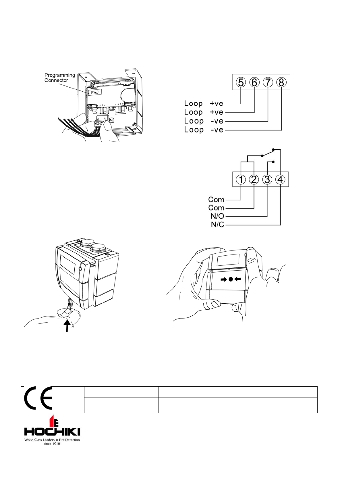
Wire the loop cables as per the wiring diagrams shown below (see figs 6 and 7). The loop connections must not be
greater than 2. 5mm
2
cable diameter for proper fixing to the terminal blocks. If r equir ed, cable screens can be
terminated at the earth terminal within the back box (see fig 4).
Once connected fix the front section of the unit c all point t o the back box, pushi ng the two halves together to
engage clips. At this point ensure the gasket seal is i ntact and in place (Note: The gasket should be replaced when
refitting or r eplac ing the Water Cover). Fix the four cover screws (see fig 1).
fig 5 fig 6
TESTING
To test the call point insert the supplied test k ey into
the aperture at the bot tom of the unit until the lower
cover opens. The non-f r angible element will drop,
thus simul ating operation of the call point (see fi g 8).
To reset the unit aft er testing remove the key and
slide the lower cover up (with the non-frangi ble
element) bac k into plac e until it clicks shut (see fig 9).
fig 7 – HCP-W(DPS) additional wiring
fig 8 fig 9
RESETTING AFTER ACTIVATION
To reset the call point after it has been activat ed, insert the supplied test key int o the aperture at the bottom of the
unit until the lower cover opens, remove key. If a glass elem ent has been used, r emove cover, replac e glass
element and replac e c ov er . Then slide the lower cover up (with the elem ent) back into place until it clic k s shut (see
fig 8).
HCP-W, HCP-WM, HCP-W(DPS) 0832-CPD-0602 07 EN54-11 Manual Call Points
HCP-W(SCI) 0832-CPD-1239 09
Hoch iki Europe (UK) Ltd
Grosvenor Road, Gillingham Business Park,
Gillingham, Kent, ME8 0SA, England Telephone:
+44(0)1634 260133 Facsimile: +44(0)1634 260132
Email: sales@hochikieurope.com
Web: www.hochikieurope.com
Hochiki Europe (UK) Ltd. reserves the right to alter the
specification of its products from time to time without notice.
Although every effort has been made to ensure the accuracy of
the information contained within this document it is not warranted
or represented by Hochiki Europe (UK) Ltd. to be a complete and
up-to-date description. Please check our web site for the latest
version of this document.
EN54-11 Manual Call Points
EN54-17:2005 Short-Circuit Isolators
2-3-0-750/ISS4/NOV09
 Loading...