

Page 1

FIRENET L@TITUDE FIRE ALARM
CONTROL PANEL OPERATING
INSTRUCTIONS
Version 1.04 |May 2019 |MAN-1432HA
Page 2

Contents |2
Version 1.04 | May 2019 | MAN-1432HA
Contents
Contents 2
Interpreting Panel Information 4
Panel LEDs 5
Fire In Zone Indicators 6
User Access Levels 8
No User Group 9
User Access Level 2 10
User Access Level 3 10
Controls 12
No User Group 12
System Information 13
Panel Tests 14
User Access Level 2 15
System Information 15
Disablements 16
Disable Positive Alarm 17
Test Zones 18
Set Date &Time 19
View Event Log 20
View Devices 21
Panel Tests 21
GUISettings 22
Page 3

Contents |3
Reviewing Commands 24
General Information 26
Operating Instructions 26
Inspecting Batteries 26
Replacing Standby Batteries 26
Related Documentation 26
Troubleshooting 28
Contact Information 30
Emergency Contact 30
Service Contact 31
Version 1.04 | May 2019 | MAN-1432HA
Page 4
InterpretingPanelInformation|4
Version 1.04 | May 2019 | MAN-1432HA
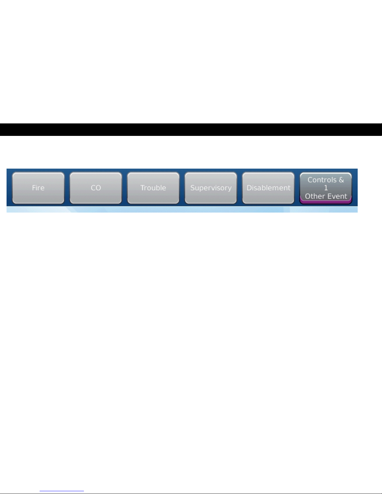
INTERPRETING PANEL INFORMATION
The event tabs will numerically indicate active events on the panel; the active event type with the highest priority will
automatically be displayed. Any event type can be accessed by pressing the associated tab. Monitor the LED indicators,
Notification Appliance Circuits (NAC), and LCD messaging to interpret panel information.
Page 5
InterpretingPanelInformation|5
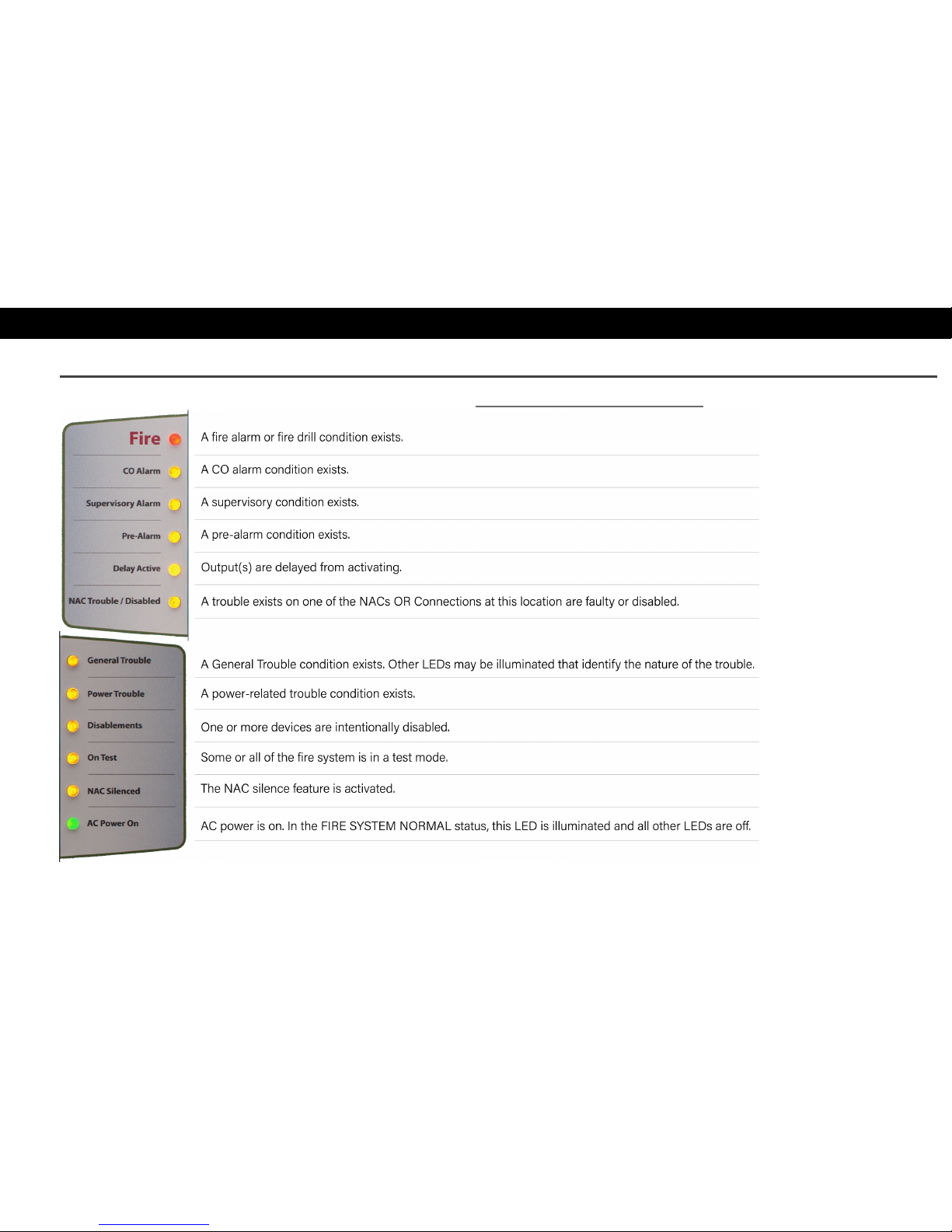
Panel LEDs
For complete information about each event type, refer to Section 1: Events and Status.
Version 1.04 | May 2019 | MAN-1432HA
Page 6
InterpretingPanelInformation|6
Version 1.04 | May 2019 | MAN-1432HA
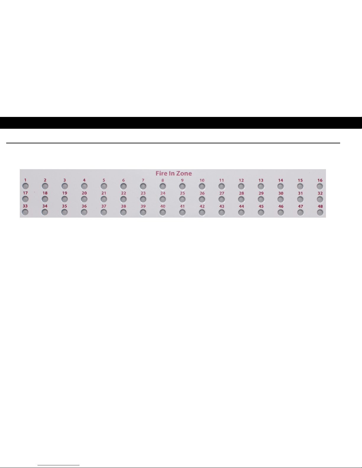
Fire In Zone Indicators
Fire In Zone indicators are an optional feature provided on the fascia of the FireNET L@titude Fire Alarm ControlPanel
in single, double, or triple bank configurations. The following figure illustrates a single bank of 48 Fire In Zone indicators:
Page 7

InterpretingPanelInformation|7
Version 1.04 | May 2019 | MAN-1432HA
Page 8
User AccessLevels| 8
Version 1.04 | May 2019 | MAN-1432HA
USER ACCESS LEVELS
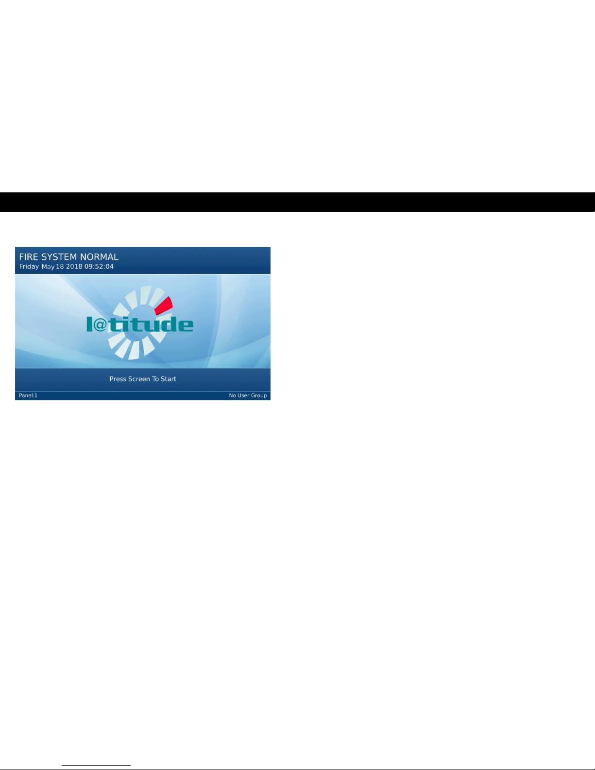
FIRE SYSTEM NORMAL
The Fire System Normal display is visible on the panel GUI
when operating in quiescent (standby) mode. Control
buttons will appear on the panel GUI when there are active
events.
Page 9
User AccessLevels| 9
No User Group
The No User Group access level does not require a log in code or operation of the front panel keyswitch. Specific
functions are restricted when operating the fire control panel in the No User Group.
This level allows users to view system information and to perform simple tests. It also provides options for testing LED
indicators of the fascia as well as color composition of the LCD panel GUI. Refer to No User Group for specific feature
details.
Version 1.04 | May 2019 | MAN-1432HA
Page 10

User AccessLevels| 10
Version 1.04 | May 2019 | MAN-1432HA
User Access Level 2
Mandatory controls are included in features of access level 2. Access can be achieved via keyswitch or configurable
password. Refer to User Access Level 2 for specific feature details.
NOTE When using a panel with a Plex-Door Enclosure, User Access Level 2 is achieved by using the key to open the door.
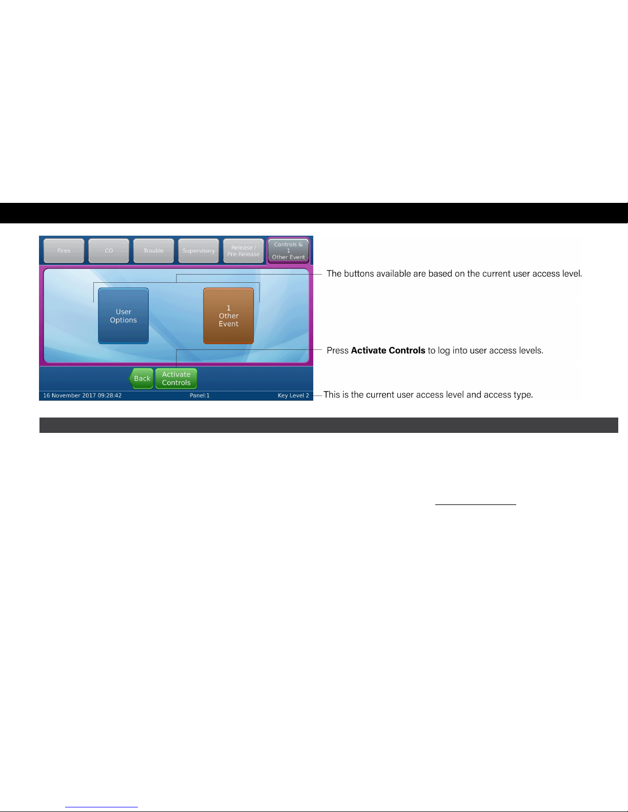
User Access Level 3
User Access Level 3 through the Activate Controls button on the panel GUI. A passwordmust be configured for Level
3 Access.
NOTE After two minutes of inactivity, the panel will return to No User Group.
Page 11

User AccessLevels | 11
Version 1.04 | May 2019 | MAN-1432HA
Page 12

Controls| 12
Version 1.04 | May 2019 | MAN-1432HA
CONTROLS
No User Group
Page 13

Controls| 13
System Information
Version 1.04 | May 2019 | MAN-1432HA
Page 14

Controls| 14
Version 1.04 | May 2019 | MAN-1432HA
Panel Tests
LAMP & BUZZER TEST
This test confirms operation of the indicator lamps and the
buzzer. To perform the Lamp & Buzzer Test:
1. Press the panel GUI during the Fire System Normal
condition.
2. Press Panel Tests > Lamp & Buzzer Test. The internal buzzer
of the fire control panel sounds and all indicator lamps light
for 5 seconds. Contact Technical Support if fascia lamps do
not light.
DISPLAY TEST
This test confirms operation of the panel GUI. To perform the
Display Test:
1. Press the panel GUI during the Fire System Normal
condition.
2. Press Panel Tests > Display Test. A confirmation window will
appear.
3. Press Continue to test the display. The panel GUI cycles
through a series of blank raster colors.
Page 15

Controls| 15
User Access Level 2
The User Options menus are as shown:
System Information
Refer to No User Group: System Information.
Version 1.04 | May 2019 | MAN-1432HA
Page 16

Controls| 16
Version 1.04 | May 2019 | MAN-1432HA
Disablements
DISABLEMENTS
Certain parts of the fire alarm system can be temporarily
disabled to suit conditions. All disablements can be
performed from this window. Press the desired button for
options when performing that specific disablement.
To view the disablement, and/or re-enable it, press the
Disablement tab. All current disablements will be displayed,
with options to Enable or show More Details. Alternatively,
there will be an Enable All button at the bottom of the
window.
Page 17

Controls| 17
Disable Positive Alarm
DISABLE POSITIVE ALARM
The Positive Alarm Sequence (PAS) provides a fire alarm
delay if the responding party manually silences the alarm at
the control panel. This action provides time to investigate an
alarm before evacuating a building.
To disable the positive alarm, press Disable Positive
Alarm and choose On or Off on the screen that appears.
Version 1.04 | May 2019 | MAN-1432HA
Page 18

Controls| 18
Version 1.04 | May 2019 | MAN-1432HA
Test Zones
TEST ZONES
To test zones on the fire control panel:
1. Press Test Zones on the panel GUI.
2. Check the desired boxes on the Test Zones window.
3. Press Details View for a more detailed view of the available zones.
4. Press Submit. Select Yes or No for the NACs On field and press
Submit to test the zones. The zone(s) will be tested and the
appropriate LEDs will light.
To view the test, and/or restore the zone, press the Controls &
Other Events tab > (#)Zone in Test. All currently tested zones
will be displayed, with options to Restore or show More Details.
Alternatively, there will be a Restore All button at the bottom of
the window.
Page 19

Controls| 19
Set Date &Time
SET DATE & TIME
Use this option to set the date and time. Use the arrows to
increase or decrease the value for each field, or press the
field to manually enter a new value.
Version 1.04 | May 2019 | MAN-1432HA
Page 20

Controls| 20
Version 1.04 | May 2019 | MAN-1432HA
View Event Log
VIEW EVENT LOG
This option displays the panel event log.
l Press More Details to display additional information about
the selected event.
l Press More Options to filter the results by event type, date,
panel, loop, zone, and/or address.
Page 21

Controls| 21
View Devices
VIEW DEVICES
To view the connected devices, press View Devices and
select the desired Loop or Zone to view the connected
devices.
Panel Tests
Refer to No User Group: Panel Tests.
Version 1.04 | May 2019 | MAN-1432HA
Page 22

Controls| 22
Version 1.04 | May 2019 | MAN-1432HA
GUISettings
GUI SETTINGS
To adjust the settings on the panel, press GUI Settings. The
following options are available:
Dim screen with ambient light: Yes
No
Buzz buzzer on screen touch: Yes
No
Keyboard Language
NOTE Only available if your
panel has been configured with
additional languages.
English
Deutsch
French
Italian
Spanish
Portuguese
Russian
Page 23

Controls| 23
Version 1.04 | May 2019 | MAN-1432HA
Page 24

ReviewingCommands|24
Version 1.04 | May 2019 | MAN-1432HA
REVIEWING COMMANDS
The control panel must be in User Access Level 2 or above to operate commands; the following commands may be
available, depending on active event types.
Silence Alarms
The Silence Alarms button silences the internal buzzer and all notification appliances as programmed.
This will not affect the GUI display or LED indicators.
Re-sound Alarms
Press Re-sound Alarms to reactivate the internal buzzer and notification appliances as programmed. The
Silence Alarms button re-appears on the panel GUI after performing the Re-sound Alarms command.
Buzzer Silence The Buzzer Silence button silences the internal buzzer. No other outputs are silenced by this button.
Page 25

ReviewingCommands|25
Reset System
Press Reset System to clear latching events.
NOTE Latching events remain active until a system reset is performed, even after resolving the cause of
the event. Non-latching events do not require a system reset and will clear after correcting the cause of the
event.
To reset the fire control panel from the latching input:
1. Clear alarm conditions from external devices.
2. Press Reset System to reset the latching events and restore the panel to the Normal Standby
Condition. After the system resets, the internal buzzer and external NACs of the fire control panel are
silenced, and panel returns to a quiescent state.
WARNING! Alarm notification signals should not be silenced until all occupants have been evacuated.
Version 1.04 | May 2019 | MAN-1432HA
Page 26

GeneralInformation | 26
Version 1.04 | May 2019 | MAN-1432HA
GENERAL INFORMATION
Operating Instructions
These operating instructions shall be placed near the panel.
Inspecting Batteries
Inspect the standby batteries annually to determine the connection integrity to the FireNET L@titude Fire Alarm
ControlPanel. The fire control panel contains sealed lead acid batteries to provide standby power in the event of power
failure. The standby batteries have a life expectancy of 3 to 5 years. Test the standby batteries annually in accordance
with the battery manufacturer’s recommendations to determine their suitability for continued standby operation.
Replacing Standby Batteries
Replace standby batteries when the service period reaches 3 to 5 years or when the low battery message is present on
LCD display. The standard size cabinet of the panel accepts battery sizes up to 28 Ah. Batteries larger than 28 Ah may
be mounted remotely in a UL listed battery cabinet. Batteries smaller than 28 Ah do not require special cabinet mounting
considerations. The 5.25 A power supply charges up to 60 Ah; the 10.25 A power supply charges up to 100 Ah.
Related Documentation
The following document shall be used to provide additional information for installing and operating the FireNET L@titude
Fire Alarm ControlPanel:
FireNET L@titude Alarm ControlPanel Installation Manual (MAN-1431HA)
Page 27

GeneralInformation | 27
Version 1.04 | May 2019 | MAN-1432HA
Page 28

Troubleshooting| 28
Version 1.04 | May 2019 | MAN-1432HA
TROUBLESHOOTING
The following network-related troubles can occur on the FireNET L@titude Fire Alarm ControlPanel. See the detailed
descriptions below for explanations on each trouble message.
Trouble Message Description
Network Communications Trouble
This event indicates there is no communication between this panel and its neighbor. This could
be caused by a configuration error (such as using the wrong baud rate), a wiring error, or
damage to the wires connecting the panel to its neighbor. If this trouble occurs on one link on
the panel, then the panel is still in communication with other panels on the network. If this
trouble occurs on both links on the panel, then the panel is no longer in communication with
other panels on the network.
Unexpected Network Node
This event indicates a panel has been detected on the network that is not in the configuration.
This is a configuration error, and should never occur once the network has been properly
configured.
Network Card Missing
This event indicates that the panel is configured for networking, but there is no network card
installed, or it is installed incorrectly. This trouble may also occur if the network card processor
fails.
Connection Error
This event indicates that the panel has failed to get a meaningful result for the link impedance
measurement. This may occur if stray leakage current enters the link wiring from elsewhere, or
if there is a component failure or missing jumper on the network card. This event may also be
shown when the network is disconnected or when the NET OUT+ wire is disconnected.
Network Panel Missing
This event indicates that another panel is configured but has not been found on the network.
This may occur if the missing panel is switched off or disconnected from the network. This
fault will also occur if there is no communication between a panel and either of its neighbors on
Page 29

Troubleshooting| 29
Trouble Message Description
both links. In this case, the panel will show multiple instances of this trouble; one for each other
panel on the network.
Network Node Double Addressed
This event indicates that more than one panel on the network has the same node number. This
is a configuration error, and should never occur once the network has been properly configured.
Full Short Circuit Trouble
This event indicates that a short circuit has been detected by the link impedance
measurement. This indicates a wiring error, or damage to the wires connecting the panel to its
neighbor.
Full Open Circuit Trouble
This event indicates that an open circuit has been detected by the link impedance
measurement. This indicates a wiring error, or damage to the wires connecting the panel to its
neighbor. The following two troubles are optional, and are not included in the default firmware
build.
Partial Short Circuit Trouble
This event indicates that the link impedance measurement has detected an impedance below
the normally expected range.
Partial Open Circuit Trouble
This event indicates that the link impedance measurement has detected an impedance above
the normally expected range.
Version 1.04 | May 2019 | MAN-1432HA
Page 30

ContactInformation | 30
Version 1.04 | May 2019 | MAN-1432HA
CONTACT INFORMATION
Emergency Contact
Contact the company or individual responsible for providing assistance in the event of an emergency. In the event of an
emergency, notify:
Name
Company
Primary Telephone
Secondary Telephone
Cell Phone
Address
City
State
Page 31

ContactInformation | 31
Service Contact
Contact the company or individual responsible for providing service:
Name
Company
Primary Telephone
Secondary Telephone
Cell Phone
Address
City
State
Version 1.04 | May 2019 | MAN-1432HA
 Loading...