

Page 1

FireNET 4127
Analog Addressable Fire Alarm System
Installation and Operation Manual
Hochiki America Corporation
7051 Village Drive, Suite 100
Buena Park, CA 90621-2268
714.522.2246 Corporate Headquarters
800.845.6692 Technical Support
http://www.hochiki.com
FireNET 4127 I & O Manual 1 v1.90 UL
Version 1.90 - UL
Created: 08/15/05
Updated: 08/24/2010
PN# 1700-09948
Page 2

Table of Contents
Table of Contents ........................................................................................................................... 2
Prefix – Programming Compliance with UL864 9
Section 1 – Introduction
......................................................................................................................................................... 8
th
Edition ........................................................ 7
1.1 Basic Features .................................................................................................... 8
1.2 System Devices and Equipment ......................................................................... 9
1.2A System Devices BOSCH ................................................................................ 11
1.2B System Devices Silent Knight ........................................................................ 12
1.2.1 System Replacement Parts ......................................................................... 13
1.3 Limitations of Fire Alarm Systems .................................................................... 14
1.4 Agency Listings, Approvals, Requirements ...................................................... 17
1.4.1 Federal Communications Commission (FCC) .............................................. 17
1.4.2 Underwriters Laboratories (UL) .................................................................... 17
1.4.3 National Fire Protection Association (NFPA) ............................................... 17
Section 2 – Control Panel Installation
....................................................................................................................................................... 18
2.1 What’s in the Box? ............................................................................................ 18
2.2 Environmental Specifications ............................................................................ 18
2.3 Control Panel Layout ........................................................................................ 19
2.3.1 Front Panel Layout, Standard Build ............................................................. 19
2.3.2 Front Panel Layout, Denver Door Build ....................................................... 20
2.3.3 Control Panel Annunciator, Control Unit and Power Supply Layout ............ 21
2.4 Mounting the Control Panel .............................................................................. 22
2.5 Wiring Specifications ........................................................................................ 22
2.5.1 Suggested Routing of AC Power ................................................................. 23
2.6 Battery Calculations .......................................................................................... 24
2.7 Electrical Ratings .............................................................................................. 27
2.8 Specifications ................................................................................................... 30
Section 3 - Power Supply and Main Control Unit Connections
....................................................................................................................................................... 31
3.1 AC Power Connection ...................................................................................... 31
3.2 Battery Connection ........................................................................................... 31
3.3 Auxiliary Power Connection .............................................................................. 32
3.4 Notification Appliance Circuit Connection ......................................................... 34
3.5 Voltage Routing and Relay Output Connection ................................................ 35
3.5.1 Voltage Routing Outputs .............................................................................. 35
3.5.2 Relay Outputs .............................................................................................. 36
3.6 Digital Input Connection .................................................................................... 37
3.7 Using a Printer .................................................................................................. 38
Section 4 – Expander Board Installation
....................................................................................................................................................... 39
2
FireNET 4127 I & O Manual v1.90 UL
Page 3

4.1 Compatible Expander Boards ........................................................................... 39
4.2 General Installation of RS-485 Bus Devices ..................................................... 40
4.2.1 Wiring Distance and Mounting Locations ..................................................... 40
4.2.2 Addressing ................................................................................................... 41
4.2.3 Terminating .................................................................................................. 41
4.2.4 Power Connections ...................................................................................... 42
4.2.5 COMMS Connection .................................................................................... 42
4.3 FN-4127-IO - Input / Output Board ................................................................... 43
4.3.1 Configuring Inputs ........................................................................................ 43
4.3.2 Configuring Outputs ..................................................................................... 44
4.3.3 LED Indicators ............................................................................................. 45
4.4 Reserved for Future Use .................................................................................. 45
4.5 Reserved for Future Use .................................................................................. 45
4.6 FN-4127-SLC – Dual SLC Loop Expander ....................................................... 46
4.6.1 Installation of the FN-4127-SLC ................................................................... 46
4.7 FN-LCD-S Serial Liquid Crystal Display Annunciator ...................................... 47
4.7.1 Installation of the FN-LCD-S ........................................................................ 47
Section 5 – SLC Device Installation
....................................................................................................................................................... 50
5.1 Compatible SLC Devices .................................................................................. 50
5.2 Number of Devices ........................................................................................... 52
5.3 SLC Loop Wiring .............................................................................................. 52
5.3.1 Class B SLC Loop Wiring Distance ............................................................. 53
5.3.2 Class A SLC Loop Wiring Distance ............................................................. 54
5.4 Addressing Devices .......................................................................................... 55
5.4.1 Detector Addressing .................................................................................... 57
5.4.2 4-S Module and AMS Addressing ............................................................... 57
5.4.3 Mini Module Addressing .............................................................................. 58
5.5 Smoke and Heat Detector Wiring ..................................................................... 59
5.6 Analog Duct Detector Wiring ............................................................................ 60
5.6.1 DH98-A Analog Duct Detector ..................................................................... 61
5.6.2 DH98-AR Analog Duct Detector with Relay ................................................. 62
5.7 FRCME-4 Input Module Wiring ......................................................................... 63
5.8 FRCME-S Mini Input Module (w/ Terminal Blocks) ........................................... 64
5.9 FRCME-P Mini Input Module (w/ Pigtails) ......................................................... 65
5.10 FRCME-M Mini Input Module (w/ Terminal Blocks) ........................................ 66
5.11 FRCMA / FRCMA-I Input Module ................................................................... 67
5.12 R2M Dual Relay Module Wiring ...................................................................... 69
5.13 SOM Supervised Output Module .................................................................... 70
5.14 SOM-A / SOM-AI Supervised Class A Output Module .................................... 71
5.15 SOM-R Supervised Output Module (Preaction Sprinkler Systems) ................ 72
5.15 CZM Conventional Zone Module .................................................................... 76
5.16 DIMM Dual Input Monitor Module ................................................................... 77
5.17 SCI Short Circuit Isolator Module .................................................................... 78
5.17.1 Class A Operation ...................................................................................... 79
5.17.2 Class B Operation ...................................................................................... 80
5.18 ASB Analog Sounder Base ............................................................................. 81
5.19 AMS Addressable Manual Pull-Station ........................................................... 82
3
FireNET 4127 I & O Manual v1.90 UL
Page 4

Section 6 - Network Connections
....................................................................................................................................................... 83
6.1 Compatible Network Devices ............................................................................ 83
6.1.1 FN-4127-NIC Network Interface Card .......................................................... 84
6.1.2 FN-LCD-N Network Liquid Crystal Display Annunciator .............................. 89
Section 7 - Basic Front Panel Operations and Programming .................................................. 91
(Access Level 1, 2, and Real-Time Operation)
....................................................................................................................................................... 91
7.1 Operating Modes .............................................................................................. 92
7.1.1 Access Level 1 ............................................................................................. 92
7.1.2 Access Level 2 ............................................................................................. 92
7.1.3 Access Level 3 ............................................................................................. 92
7.2 Access Level 1 Operations ............................................................................... 92
7.2.1 Performing a Lamp Test .............................................................................. 92
7.2.2 More Fire Events ......................................................................................... 93
7.2.3 More Events ................................................................................................. 93
7.2.4 Menu Navigation (Up, Down, Left, Right Arrows, Enter / Exit Buttons) ........ 93
7.2.5 Help (?) ........................................................................................................ 93
7.3 Access Level 2 Operations ............................................................................... 94
7.3.1 Entering Access Level 2 .............................................................................. 94
7.3.2 Silencing an Alarm ....................................................................................... 94
7.3.3 Resounding an Alarm .................................................................................. 94
7.3.4 Resetting an Alarm ...................................................................................... 95
7.3.5 Initiating a Fire Drill ...................................................................................... 95
7.3.6 Silence the Panel Sounder .......................................................................... 95
7.4 Advanced Access Level 2 Operations .............................................................. 96
7.4.1 Access Level 2 Main Menu .......................................................................... 96
7.4.2 Disablements ............................................................................................... 96
7.4.3 View Devices ............................................................................................... 98
7.4.4 Test Zones ................................................................................................... 98
7.4.5 Set System Time ......................................................................................... 99
7.5 Panel Operation ................................................................................................ 99
7.5.1 Fire Condition .............................................................................................. 99
7.5.2 Trouble Condition ...................................................................................... 100
7.5.3 Supervisory Condition ................................................................................ 101
7.5.4 Pre-Alarm Condition .................................................................................. 102
Section 8 - Advanced Front Panel Operations and Programming (Access Level 3)
..................................................................................................................................................... 103
8.1 Access Level Overview ................................................................................... 103
8.1.1 Entering Access Level 3 ............................................................................ 103
8.2 Access Level 3 Menu ...................................................................................... 104
8.2.1 Edit Configuration ...................................................................................... 104
8.2.2 Set Times................................................................................................... 112
8.2.3 View Print Event Log ................................................................................. 113
8.2.4 Print Configuration ..................................................................................... 114
8.2.5 System Disablements ................................................................................ 114
8.2.6 Loop Data Test .......................................................................................... 115
4
FireNET 4127 I & O Manual v1.90 UL
Page 5

Section 9 - Loop Explorer Software Programming
..................................................................................................................................................... 116
9.1 PC Requirements ........................................................................................... 116
9.2 Installing Loop Explorer .................................................................................. 116
9.3 Launching Loop Explorer ................................................................................ 117
9.4 Connecting Your PC to the FireNET 4127 ...................................................... 117
9.4.1 Using PC Connect ..................................................................................... 117
9.4.2 Setting a COM Port .................................................................................... 122
9.5 Getting Familiar with Loop Explorer ................................................................ 122
9.5.1 User Interface ............................................................................................ 123
9.5.2 Menu and Toolbar Overview ...................................................................... 125
9.5.3 Main Tool Bar Icons ................................................................................... 132
9.5.4 Items Pane Icons ....................................................................................... 134
9.6 Developing a Site............................................................................................ 138
9.6.1 Creating a New Site ................................................................................... 138
9.6.2 Editing an Existing Site .............................................................................. 139
9.6.3 Saving a Site .............................................................................................. 140
9.7 Configuring Panels to a Network .................................................................... 141
9.7.1 Adding a Panel .......................................................................................... 141
9.7.2 Configuring and Editing a Panel ................................................................ 142
9.7.3 Editing a FN-LCD-N Network LCD Annunciator ......................................... 147
9.7.4 Reserved for Future Use ........................................................................... 147
9.7.5 Editing a Local Panel I/O ........................................................................... 148
9.7.6 Removing a Panel ..................................................................................... 148
9.8 Configuring Option Boards/Serial LCD Annunciators on a Panel ................... 149
9.8.1 Adding an Option Board/Serial LCD Annunciator ...................................... 149
9.8.2 Editing an Option Board/Serial LCD Annunciator ...................................... 149
9.8.3 Removing an Option Board/Serial LCD Annunciator ................................. 150
9.9 Configuring Panel I/O and Devices on a Loop ................................................ 151
9.9.1 Adding a Device on a Loop ........................................................................ 151
9.9.2 Editing Panel I/O and Devices on a Loop .................................................. 151
9.9.3 Changing a Device on a Loop .................................................................... 157
9.9.4 Deleting a Device on a Loop ...................................................................... 157
9.10 Loop Explorer Abilities .................................................................................. 158
9.10.1 Reserved for Future Use.......................................................................... 158
9.10.2 Cause & Effect Summary......................................................................... 158
9.10.3 Reserved for Future Use.......................................................................... 158
9.10.4 Zone Manager ......................................................................................... 158
9.10.5 Reserved for Future Use.......................................................................... 158
9.11 Loop Explorer Networking ............................................................................ 159
9.11.1 Getting it working ..................................................................................... 159
9.11.2 Using the Loop Explorer PC configuration ............................................... 159
9.11.3 Fire action ................................................................................................ 160
9.11.4 Auxiliary action ......................................................................................... 160
9.11.5 Pre-alarm action ...................................................................................... 160
9.11.6 Trouble action .......................................................................................... 160
9.11.7 Disablement action .................................................................................. 161
9.11.8 Supervisory Alarm action ......................................................................... 161
9.11.9 Test action ............................................................................................... 161
9.11.10 Status .................................................................................................... 161
5
FireNET 4127 I & O Manual v1.90 UL
Page 6

9.12 Loop Explorer Networking - Keeping a record .............................................. 164
9.13 Loop Explorer Networking - Using zones ...................................................... 171
9.14 Loop Explorer Options .................................................................................. 172
9.14.1 COM Port ................................................................................................. 172
9.14.2 Default Project Folder/ Memory Management ......................................... 172
9.14.3 Splash Screen ......................................................................................... 172
9.14.4 Other ........................................................................................................ 173
9.15 Cause and Effect Programming .................................................................... 174
9.15.1 Cause & Effect Types .............................................................................. 174
9.15.2 Cause & Effect Examples ........................................................................ 176
Section 10 - Testing and Troubleshooting
..................................................................................................................................................... 178
10.1 One Man Walk Test - TEST ZONES ............................................................ 178
10.2 View / Print Event Log .................................................................................. 179
10.2.1 View Event Log ........................................................................................ 179
10.2.2 Print Event Log ........................................................................................ 180
10.2.3 Clear Event Log ....................................................................................... 181
10.3 Loop Data Test ............................................................................................. 182
10.4 Troubleshooting ............................................................................................ 184
Section 11 - Installation Records
..................................................................................................................................................... 186
11.1 SLC Loop Point Record ................................................................................ 186
11.2 RS485 Bus Device Record ........................................................................... 186
11.3 Network Node Device Record ...................................................................... 186
Appendix A - Compatible Devices
..................................................................................................................................................... 199
A.1 Two-Wire Smoke Detectors ........................................................................... 199
A.1.1 Two-Wire Smoke Detectors BOSCH ........................................................... 200
A.2 Reserved for Future Use ................................................................................ 200
A.3 Compatible Notification Appliances ................................................................ 201
A.4 Compatible 24VDC Devices ........................................................................... 206
A.4.1 Compatible 24VDC Devices BOSCH .......................................................... 207
A.5 Using the Bosch D9068 Dialer with FireNET .................................................. 208
A.5.1 Using the Bosch D9068 Contact Dialer with FireNET (Diagram) ............... 208
A.5.2 Programming FireNET for use with the Bosch D9068 Dialer..................... 209
A.5.3 Installation notes when using the Bosch D9068 Dialer with FireNET ........ 212
A.6 Using the FN-CTM City Tie module with FireNET .......................................... 213
A.7 Using the FNV-MP with FireNET .................................................................... 214
A.8 Changing the FN-PS402 Power Supply to 240VAC operation ....................... 215
Appendix B – Panel Door Label Drawing ................................................................................. 216
Appendix C - WARRANTY ......................................................................................................... 217
6
FireNET 4127 I & O Manual v1.90 UL
Page 7

Prefix – Programming Compliance with UL864 9th Edition
Notice to Users, Installers, Authorities Having Jurisdiction, and other involved parties
This product incorporates field-programmable software. In order for the product to comply with the
requirements in the Standard for Control Units and Accessories for Fi re Alarm Systems, UL 864 9th
Edition, certain programming features or options must be limited to specific values or not used at all
as indicated below.
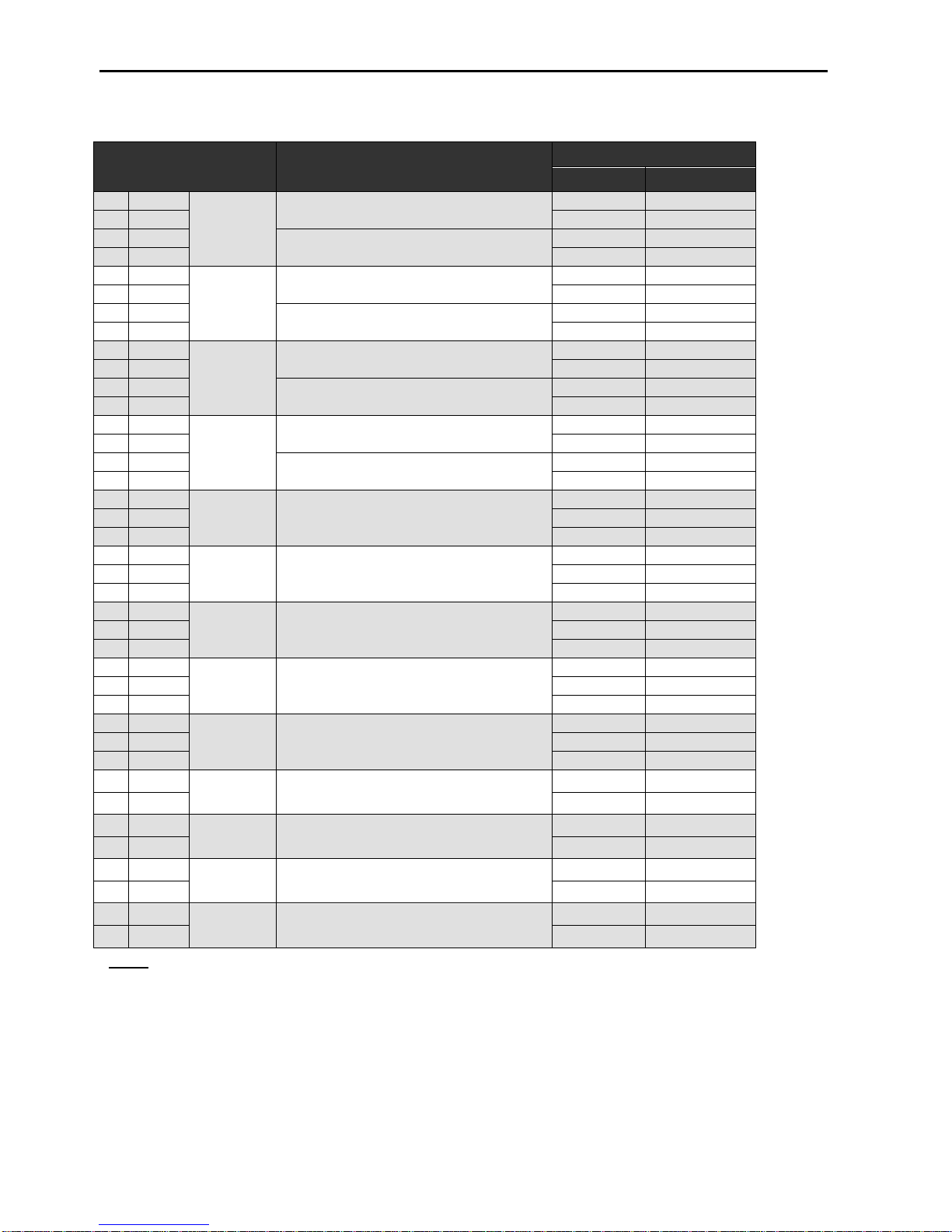
Program Feature or
Option
AC Fail Delay Yes 0 – 24 hours 1 – 3 hours
Alarm Verification Yes 5 – 60 seconds 60 second setting
Disable Buzzer Yes Enable/Disable Enable
Disable Ground Trouble Yes Enable/Disable Enable
Permitted in UL 864?
(Y/N)
Possible settings
Settings permitted in
UL864
Set Buzzer Silence
Access Level
“Waterflow Alarm” and
“General Purpose” Device
Type
Disable SOM-R No Enable/Disable None
Yes 1 or 2 2
No 0 – 120 seconds 0 seconds
7
FireNET 4127 I & O Manual v1.90 UL
Page 8

Section 1 – Introduction
The FireNET 4127 is an analog addressable fire alarm system that meets the
requirements of UL 864 9th Edition.
1.1 Basic Features
The basic FireNET 4127 control panel includes two SLC (Signaling Line Circuit)
loops. Each loop is capable of supporting 127 analog addressable points (can be
any combination of sensors and modules) for a total of 254 analog addressable
points on the basic panel. Two additional SLC loops can be added to the panel
increasing the analog addressable point capacity to 508. When analog sounder
bases are used, the upper addresses 128 – 254 are allocated to increase loop
capacity to 254 analog addressable points. This doubles the analog addressable
point capacity of the panel. The combination of analog addressable points
derived from sensors, modules, and sounder bases cannot exceed 800
addresses and sub-addresses maximum.
Up to 4.0 amps of power is available to drive the system, SLC loops, notification
appliances, and auxiliary equipment.
Four Class B notification appliance circuits rated at 2.5 amps each (see Section
2.7 and 2.8 for additional details regarding NAC circuit ratings).
Five programmable Form C relays are built-in to the control panel.
500 network-wide zones for device and circuit grouping.
Analog Smoke Detector Features:
Automatic Drift Compensation
Maintenance Alert
Adjustable Day/Night Sensitivity
Calibration checking meets sensitivity test requirements of NFPA 72.
Auto-Learn utility identifies system devices, which makes initial system start-up
easier.
8 line by 40 character graphic display provides the most intuitive operator
interface in the industry (320 characters total).
Help screens are available from the front panel and annunciator user interface to
assist in programming and operation.
512 additional points can be added to the system using the FN4127-IO 16
channel input/output boards. Each of these points can be programmed
individually to be an input or low current output. These points are for secondary
use only.
8
FireNET 4127 I & O Manual v1.90 UL
Page 9

1.2 System Devices and Equipment
The following boards, expanders and devices are available from Hochiki America
Corp. to be used with the FireNET 4127 analog addressable fire alarm system. For
a complete description and installation instructions of each product, please see the
appropriate section of this manual and the literature supplied with the device itself.
Model Description
Control Panels
FN-4127
NOTE: There are several ordering models (i.e. 2 loop, 4 loop, network options,
120/240VAC, colors, etc.). Hochiki America’s order entry department will establish
exact model and configuration at time of order. Different ordering models are also
reflected on the FireNET product datasheets.
FN-4127-NIC Network Interface Card
FN-4127-SLC Dual SLC Loop Expander Card
FN-4127-IO 16 Channel Input Output Board
FN-CTM City-Tie Module
FN-DAC Digital Alarm Communicator/Transmitter
FN-LCD-N Network LCD Annunciator
FN-LCD-S Serial LCD Annunciator
ALK-V Analog Photoelectric Smoke Sensor
ALK-V2 Analog Photoelectric Smoke Sensor
ALG-V Analog Photoelectric Smoke Sensor
AIE-EA Analog Ionization Smoke Sensor
ATG-EA Analog Heat Sensor
ACA-V Analog Photoelectric and Heat Multi Sensor
YBN-NSA-4 4” Base for Analog Sensors
HSB-NSA-6 6” Base for Analog Sensors
DH98-A Analog Duct Smoke Detector
DH98-AR Analog Duct Smoke Detector w/Relay
MS-RA, MS-RA/R, MSKA/R
FRCME-4 Input Module 4” Box Mount
FRCME-S Mini Input Module w/ Terminal Block
FRCME-P Mini Input Module w/Pigtail Leads
FRCME-M Mini Input Module w/ Terminal Block
FRCMA, FRCMA-I Class A Input Module 4” Box Mount (FRCMA-I has built-in SCI)
SOM, SOM-A, SOM-AI Supervised Output Module
SOM-R Supervised Output Module (Preaction Sprinkler Systems)
R2M Dual Relay Module
R2ML, R2ML-I Dual Relay Module, 2 amp @ 30VDC (R2ML-I has built-in SCI)
Analog/Addressable Fire Alarm Control Panel
(2 SLC Loop, expandable to 4 SLC Loop)
Control Panel Expanders
Annunciators
SLC Loop Devices
Remote Test Station for DH98A & DH98AR
9
FireNET 4127 I & O Manual v1.90 UL
Page 10

R2MH, R2MH-I Dual Relay M odule, 8 amp @ 30VDC (R2MH-I has built-in SCI)
SCI Short Circuit Isolator Module
DIMM Dual Input Monitor Module
CZM Conventional Zone Module
ASB Analog Sounder Base
AMS/KL/LP Addressable Manual Pull-Station
Accessories
TCH-B100-NS Hand-held Programmer
FN-ACC Battery/Accessory Enclosure (houses up to 33AH size batteries)
FN-ETR Enclosure Trim Ring for Panel Flush Mount
10
FireNET 4127 I & O Manual v1.90 UL
Page 11
1.2A System Devices BOSCH
The following boards, expanders and devices are available from BOSCH to be used
with the FireNET 4127 analog addressable fire alarm system. For a complete
description and installation instructions of each product, please see the appropriate
section of this manual and the literature supplied with the device itself.
Model Description
FN-4127 Analog/Addressable Fire Alarm Control Panel
D323A Analog Photoelectric Smoke Sensor
NOTE: There are several ordering models (i.e. 2 loop, 4 loop, network
options, 120/240VAC, colors, etc.). Bosch’s order entry department will
establish exact model and configuration at time of order. Different ordering
models are also reflected on the FireNET product datasheets.
(2 SLC Loop, expandable to 4 SLC Loop)
D324A Analog Ionization Smoke Sensor
D322A Analog Heat Sensor
D336A 4” Base for Analog Sensors
D321A 6” Base for Analog Sensors
D331A Analog Duct Smoke Detector
D332A Analog Duct Smoke Detector w/Relay
D326A Input Module 4” Box Mount
D339A Mini Input Module w/ Terminal Block
D327A Supervised Output Module
D335A Dual Relay Module
D333A Short Circuit Isolator Module
D5070 Hand-held Programmer
Control Panels
SLC Loop Devices
Accessories
11
FireNET 4127 I & O Manual v1.90 UL
Page 12
1.2B System Devices Silent Knight
The following boards, expanders and devices are available from Silent Knight to be
used with the FireNET 4127 analog addressable fire alarm system. For a complete
description and installation instructions of each product, please see the appropriate
section of this manual and the literature supplied with the device itself.
Model Description
SD505-APS Analog Photoelectric Smoke Sensor
SD505-AIS Analog Ionization Smoke Sensor
SD505-AHS Analog Heat Sensor
SD505-4AB 4” Base for Analog Sensors
SD505-6AB 6” Base for Analog Sensors
SD505-DUCT Analog Duct Smoke Detector
Accessories
SD505-DTS-K Remote Test Switch
SLC Loop Devices
12
FireNET 4127 I & O Manual v1.90 UL
Page 13

1.2.1 System Replacement Parts
Control Panel Repair / Replacement Parts
FN-4127-BO FireNET 4127 Control Unit Board Only (K6002)
FN-4127-CPA-BO FireNET 4127 Panel Annunciator Board Only (K6001)
FN-PS4 FireNET 4 Amp Power Supply (UL864 8th Edition Compliant)
FN-PS402* FireNET 4 Amp Power Supply (UL864 9th Edition Compliant)
FN-ENC FireNET Enclosure Complete
FN-ENC-DO FireNET Enclosure Door Only
FN-ENC-BC FireNET Enclosure Back-Can Only
FN-PMP FireNET Panel Mounting Plate
FN-PBS FireNET Panel Bonding Strap
FN-PGB FireNET Panel Grounding Block
FN-EOL FireNET Panel EOLR (package)
FN-STO FireNET Panel Standoffs (for panel covers)
FN-PRC FireNET Panel Ribbon Cables (package)
FN-FUS FireNET Main AC Input Fuse
FN-FUS-BATT FireNET Battery Input Fuse
FN-BLJ FireNET Battery Leads & Jumper
FN-MAN FireNET Installation Manual
FN-PDL FireNET Panel Door Label
FN-LSW Loop Explorer Software CD
FN-X187 Programming Cable (Standard)
FN-S187 Programming Cable (Jacketed)
FN-SKDK Spare Keys for Door Keyswitch
FN-SKCK Spare Keys for Controls Keyswitch
FN-ECK Enable Controls Keyswitch
FN-BLE Battery Leads for Accessory Enclosure (extended length 3.28ft)
FN-LCD-N-ETR Enclosure Trim Ring for Network Annunciator Flush Mount
FN-LCD-N-BB Network Annunciator Back-box
FN-LCD-N-CPA-BO Network Annunciator Annunciator Board Only (K6001 R version)
FN-LCD-N-BO Network Annunciator Control Unit Board Only (K6007)
FN-LCD-S-BO Serial Annunciator Control Unit Board Only (K6017)
FN-LCD-S-BB Serial Annunciator Back-box
FN-EBS Expansion Boards Standoffs (SLC board & I/O board stacking)
FN-ENC-DD Denver Do or Enclosure Front Door, including clear window
FN-CB-DD Denver Door Circuit Board Mounting Plate
FN-ENC-BC-DD Denver Door Enclosure Back-Can Only
FN-KEY-DD
FN-S-DD Access Level 2 Switch for Denver Door Build
*NOTE: 240VAC option available
CAT-30 Enclosure Key and Lock for FireNET and FireNET
Denver Door version
13
FireNET 4127 I & O Manual v1.90 UL
Page 14

1.3 Limitations of Fire Alarm Systems
Follow Recommended Installation Guidelines: To achieve early fire detection, fire
detection sensors should be installed in all rooms and areas of a house, apartment,
or building in accordance with the recommendations of the National Fire Protection
Association Standard 72 (NFPA 72), manufacturer’s recommendations, state and
local codes, and the recommendations contained in Guide for the Proper Use of
System Smoke Detectors, which is made available at no charge to all installing
dealers. Generally, the standards and recommendations include the following (but
installers should refer to the specific guidelines above before installing):
• Sleeping Rooms:
room.
• Hallways: More than one smoke detector should be installed in a hallway if it
is more than 30 feet long.
• At least Two Smoke Detectors: There should never be less then two smoke
detectors per apartment or residence.
• Smoke Detectors in Alarm, Electrical, or Phone Locations: Smoke detectors
should be located in any room where an alarm control is located or an alarm
control connects to an electrical source or phone line. If detectors are not so
located, a fire within the room could prevent the alarm control from reporting
a fire.
• Notification Systems: All fire alarm systems require notification devices,
including sirens, bells, horns, and/or strobes. In residential applications, each
automatic alarm initiating device when activated should cause the operation
of alarm notification device that should be clearly audible in all bedrooms
over ambient or background noise levels (at least 15dB above noise) with all
intervening doors closed.
• Alarm in Every Bedroom and Level of Residence: A smoke detector with an
integral sounder (smoke alarm) should be located in every bedroom and an
additional notification device should be located on each level of a residence.
• Maintenance: A maintenance agreement should be arranged through the
local manufacturer’s representative and maintenance should be performed
annually by authorized personnel only. To keep a fire alarm system in
excellent working order, ongoing maintenance is required per the
manufacturer’s recommendations and UL and NFPA standards. At a
minimum the requirements of Chapter 7 of NFPA 72 (1999) shall be followed.
• Test Weekly:
sensors and transmitters are working properly. The most common cause of
an alarm system not functioning when a fire occurs is inadequate
maintenance.
Alarms Cannot Guarantee Warning or Protection: Fire alarm system cannot
guarantee warning or protection against fire in every potential situation. A study by
the Federal Emergency Management Agency (an agency of the United States
government) indicated that smoke detectors may not go off or give early warning in
as many as 35% of all fires.
Smoke detectors should be installed in every sleeping
The alarm system should be tested weekly to make sure all
14
FireNET 4127 I & O Manual v1.90 UL
Page 15

Limitation on Fire Alarm Effectiveness: A fire alarm system may not provide timely
or adequate warning, or simply may not function, for a variety of reasons. For
example:
• No Detection: Particles of combustion or smoke from a developing fire may
not reach the sensing chambers of smoke detectors because:
1. Barriers (such as closed or partially closed doors, walls, or chimneys)
may inhibit particle or smoke flow.
2. Smoke particles may become cold, stratify, or not reach the ceiling
or upper walls where detectors are located.
3. Smoke particles may be blown away from detectors by air outlets.
4. Smoke particles may be drawn into air returns before reaching the
detector.
• No Multi-Floor Detection: In general, smoke detectors on one level of a
structure cannot be expected to sense fires developing on another level.
• Insufficient Smoke: The amount of smoke present may be insufficient to
alarm smoke detectors. Smoke detectors are designed to alarm, at various
levels of smoke density. If such density levels are not created by a
developing fire at the location of the detector, the detector will not go into
alarm.
• Smoldering vs. Flaming Fires: Smoke detectors, even when working
properly, have sensing limitations. Detectors that have photoelectric sensing
chambers tend to detect smoldering fires better than flaming fires, which
have little visible smoke. Detectors that have ionizing-type sensing chambers
tend to detect fast flaming fires better than smoldering fires. Because fires
develop in different ways and are often unpredictable in their growth, neither
type of detector is necessarily best and a given type of detector may not
provide adequate warning of a fire.
• False Alarms and Pre-Fire Disconnection: Smoke detectors are subject to
false alarms and nuisance alarms and may have been disconnected by
users. For example, a smoke detector located in or near a kitchen may go
into nuisance alarm during normal operation of kitchen appliances. In
addition, dusty or steamy environments may cause a smoke detector to
falsely alarm. If the location of a smoke detector causes an abundance of
false alarms or nuisance alarms, do not disconnect the smoke detector, call a
professional to analyze the situation and recommend a solution.
• Fast Fires and Explosions: Smoke detectors cannot be expected to provide
adequate warning of fires caused by arson and children playing with matches
(especially within bedrooms), smoking in bed, violent explosions (caused by
escaping gas, improper storage of flammable materials, etc.).
• Heat Detectors:
Heat detectors do not sense particles of combustion and are
designed to alarm only when heat on their sensors increases at a
predetermined rate or reaches a predetermined level. Heat detectors are
designed to protect property, not life.
15
FireNET 4127 I & O Manual v1.90 UL
Page 16

• Unheeded Warning: Warning devices (including horns, sirens, and bells)
may not alert people or wake up sleepers who are located on the other side
of closed or partially open doors. A warning device that activates on a
different floor or level of a dwelling or structure is less likely to awaken or alert
people. Even persons who are aware may not notice the warning if the alarm
is muffled by noise from a stereo, radio, air conditioner or other appliance, or
by passing traffic. Audible warning devices may not alert the hearing
impaired (strobes or other devices should be provided to warn these people).
Any warning device may fail to alert people with a disability, deep sleepers,
people who have recently used alcohol or drugs, or people on medication or
sleeping pills.
• Strobes: Strobes can under certain circumstances, cause
seizures in people with conditions such as epilepsy.
• Drills: Studies have shown that certain people, even when they
hear a fire alarm signal, do not respond or comprehend the
meaning of the signal. It is the property owner’s responsibility to
conduct fire drills and other training exercises to make people
aware of fire alarm signals and instruct on the proper reaction to
alarm signals.
• Hearing Loss: In rare instances, the sounding of a warning
device can cause temporary or permanent hearing loss.
• Telephone Transmissions Problems: Telephone lines needed to transmit
alarm signals from a premises to a central station may be out of service or
temporarily out of service. For added protection against telephone line failure,
backup radio transmission systems are recommended.
• System Failure With Age or Lack of Maintenance: System components,
though designed to last many years, can fail at any time. As a precautionary
measure, it is recommended that smoke detectors be checked, maintained,
and replaced per manufacturer’s recommendations.
• Electrical Power Problems: System components will not work without
electrical power. If system batteries are not serviced or replaced regularly,
they may not provide battery backup when AC power fails.
• High Air Velocity or Dusty or Dirty Environments: Environments with high air
velocity or that are dusty or dirty require more frequent maintenance.
Importance of Maintenance: In general, fire alarm systems and devices will not
work without power and will not function property unless they are maintained and
tested regularly.
Alarm is Not Substitute for Insurance: While installing a fire alarm system may
make the owner eligible for a lower insurance rate, an alarm system is not a
substitute for insurance. Property owners should continue to act prudently in
protecting the premises and the people in their premises and should properly insure
life and property and buy sufficient amounts of liability insurance to meet their
needs.
16
FireNET 4127 I & O Manual v1.90 UL
Page 17

1.4 Agency Listings, Approvals, Requirements
1.4.1 Federal Communications Commission (FCC)
The FireNET 4127 has been verified to comply with FCC Rules Part 15, Class A
Operation is subject to the following conditions:
1. This device may not cause radio interference.
2. This device must accept any interference received, including any that may cause
undesired operation.
1.4.2 Underwriters Laboratories (UL)
The FireNET 4127 is UL864 9th Edition listed and is suitable for use as a commercial
protected premises control unit as follows:
-Local signaling unit
-Types of signaling services are automatic, manual, waterflow, & sprinkler
supervisory.
-Style 4, 6, or 7 for Signaling Line Circuits
-Style Y for Notification Appliance Circuits
-Non-coded signaling
-Central Station Service – DACT type (protected premise)
-Remote Station Service – DACT type (protected premise)
-Proprietary Service – DACT type (protected premise)*
-Auxiliary Service – local energy type (protected premise)
*When used with the Bosch D6600 Digital Alarm Communicator Receiver.
1.4.3 National Fire Protection Association (NFPA)
Install and configure the FireNET system in accordance with NFPA 72 and 13.
All field wiring must be installed in accordance with NFPA 70 National Electric Code
(Article 760).
17
FireNET 4127 I & O Manual v1.90 UL
Page 18

Section 2 – Control Panel Installation
2.1 What’s in the Box?
The FireNET 4127 control panel includes the following components and hardware:
Control panel cabinet with hinged door.
Power supply module pre-mounted in cabinet
Control panel annunciator & RS232 interface pre-mounted in cabinet
Main control unit pre-mounted in cabinet.
Two keys for the cabinet lock and two keys for the Enable Controls keyswitch.
Note that the Denver Door build does not include keys for the Enable Controls
keyswitch.
(2) 10k ohm EOL resistors PN# 0400-01046, (4 or 8) zero ohm jumpers PN#
0400-01025, (1) 1N4004S diode PN# 0400-01024, and (4) EOLD devices PN#
0400-1023.
Battery jumper for series connection of 2 – 12 volt batteries.
Installation Manual (PN# 1700-09948)
2.2 Environmental Specifications
The FireNET 4127 main control panel should be installed in locations where it will NOT
be exposed to temperatures outside the range of 32
range of 10%-85% non-condensing.
The FireNET 4127 control panel must be installed so that it is not subjected to damage
by water and condensation. AVOID mounting the control panel cabinet directly on
exterior masonry walls, in areas subject to plumbing leaks, in areas subject to splash
from sprinkler test valves, or in high humidity areas.
The FireNET control panel is intended for installation in indoor environments in a dry
location.
18
FireNET 4127 I & O Manual v1.90 UL
o
F – 120oF or humidity outside the
Page 19
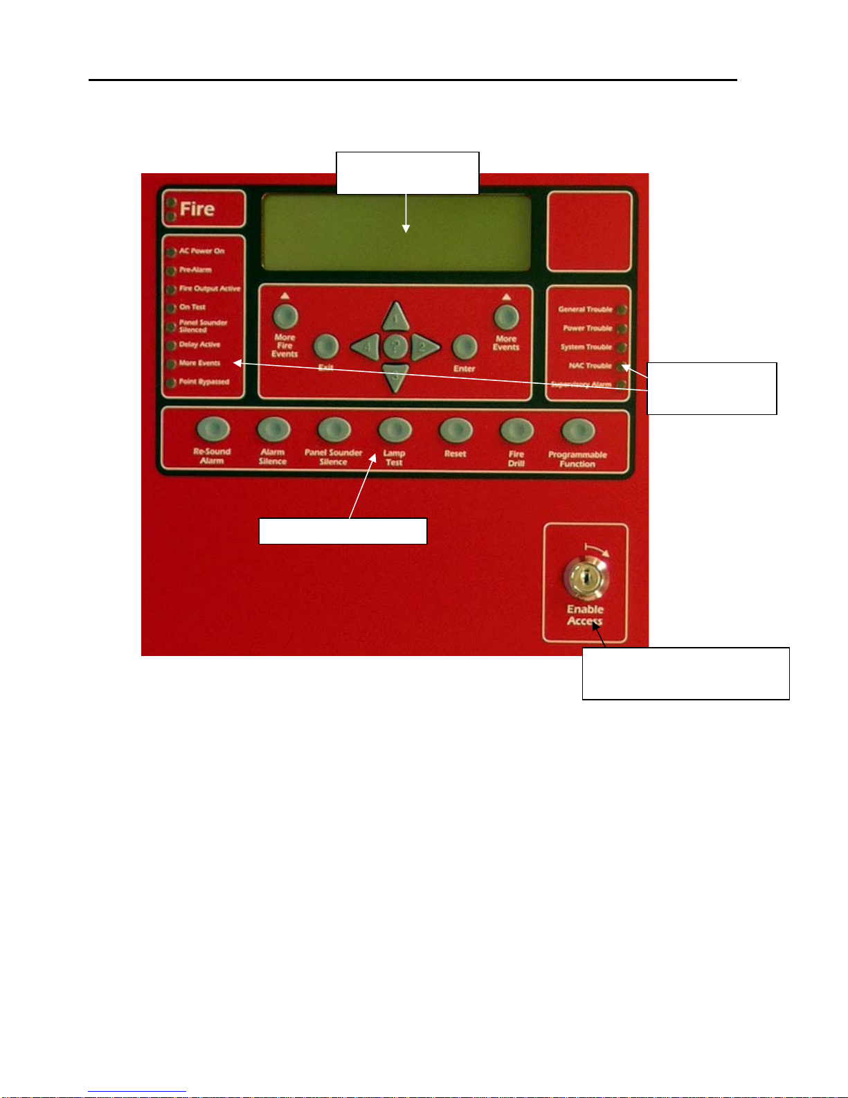
2.3 Control Panel Layout
2.3.1 Front Panel Layout, Standard Build
Front Panel Controls
8-Line x 40
character LCD
Front Panel
Indicators
Enable Controls Key-switch
(Access Level 2)
Figure 2-3-1
19
FireNET 4127 I & O Manual v1.90 UL
Page 20

2.3.2 Front Panel Layout, Denver Door Build
Figure 2-3-2
Figure 2-3-2a
20
FireNET 4127 I & O Manual v1.90 UL
Page 21
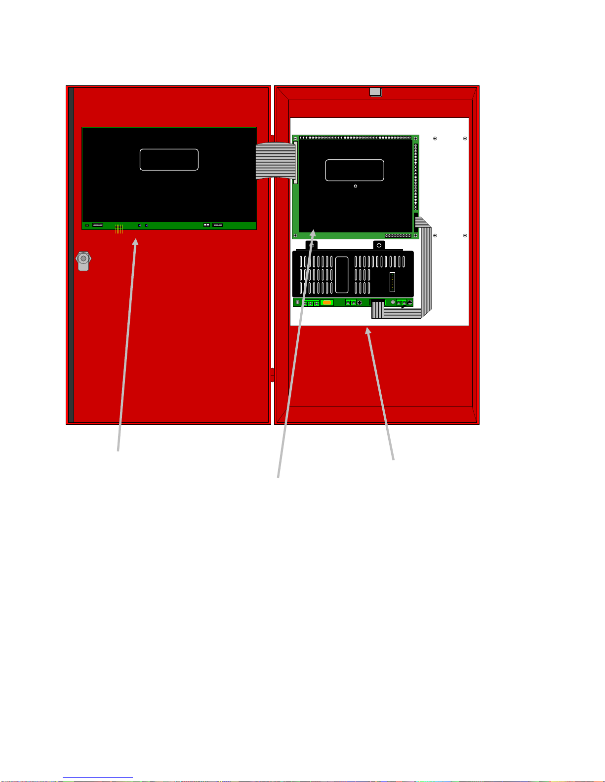
2.3.3 Control Panel Annunciator, Control Unit and Power Supply Layout
WARNING!
DO NOT PLUG OR UNPLUG RIBBON CABLES
WHILE BOARD IS POWERED. STATIC
SENSITIVE CIRCUITS. OBSERVE STATIC
HANDLING PROCEDURES AT ALL TIMES
WARNING!
DO NOT PLUG OR UNPLUG RIBBON CABLES
WHILE BOARD IS POWERED. STATIC
SENSITIVE CIRCUITS. OBSERVE STATIC
HANDLING PROCEDURES AT ALL TIMES
+
-
Control Panel Annunciator &
RS 232 Interface
Printer Connection
PC Connection
Front Panel Controls
Figure 2-3-3
Main Control Unit
SLC Loops
Programmable Relays
Notification Appliance
Circuits
Programmable Outputs
Remote Control and Aux
Inputs
Expansion Board
Connections
Network Connections
Aux Power Output
Power Supply Module
AC Power Connection
Battery Connection
21
FireNET 4127 I & O Manual v1.90 UL
Page 22

2.4 Mounting the Control Panel
Consult the environmental specifications listed in Section 2.2 to determine a suitable
location to mount the FireNET 4127 main control panel.
The panel should be mounted so that it is accessible to service personnel and located
in a secure area.
Do not mount directly to a concrete wall. Use a suitable standoff material such as
plywood to keep condensation away from the control panel.
2.5 Wiring Specifications
Care should be taken when wiring the system to avoid situations that would contribute
to inducing electrical noise from one wire to another. Induced noise can interfere with
telephone communications or cause erratic system operation. Follow these guidelines
to plan your system wiring prior to installation.
• Route high and low voltage wiring separately. Maintain a minimum 2” separation
between high and low voltage wiring throughout the building.
• Route control panel wiring around the perimeter of the enclosure. A minimum
.25” separation is required between high and low voltage wiring.
• Identify which group each wire or cable is associated with from the list below.
Isolate each groups wiring as much as possible. Avoid running a single multiconductor cable for multiple groups of conductors.
• AC Power - Main Power Supply
• Notification Appliances
• SLC Circuits
• Relay Outputs
• Voltage Outputs
• Remote Control and Auxiliary Inputs
• Network Wiring (Shielded wire required)
• RS485 Bus Wiring (Shielded wire required)
• Keep wiring from different groups separated as much as possible. If you must
share the same conduit with different conductor groups consider using shielded
cable.
• If shielded cable is used terminate the shield to the earth ground terminal block
in the main control panel and leave open at field side of cable. Do not ground at
both ends of cable.
• All terminals on the FireNET control can accept wire gauges from 22AWG and
14AWG.
22
FireNET 4127 I & O Manual v1.90 UL
Page 23
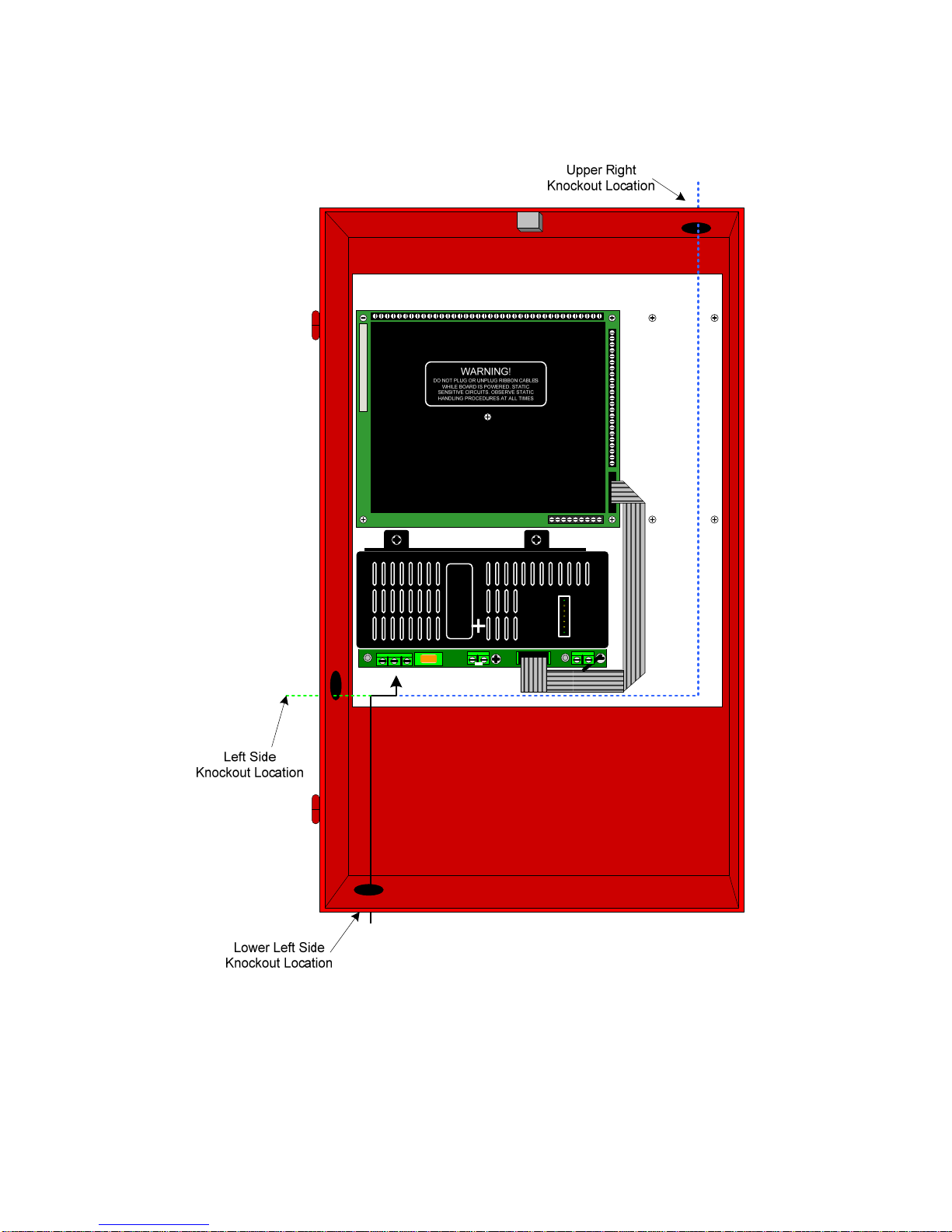
2.5.1 Suggested Routing of AC Power
Route the AC input power wiring as outlined below. Follow recommendations outlined
in section 2.5 regarding the separation of high and low voltage wiring.
The preferred entry location for AC input power is via the left side knock-out (see green
dotted line above). DO NOT route AC input power across the main control board
(K6002), the ribbon cable interconnects, or directly across or adjacent to the lowvoltage connections made on terminal strips X1 (top) or X2 (side).
23
FireNET 4127 I & O Manual v1.90 UL
Page 24
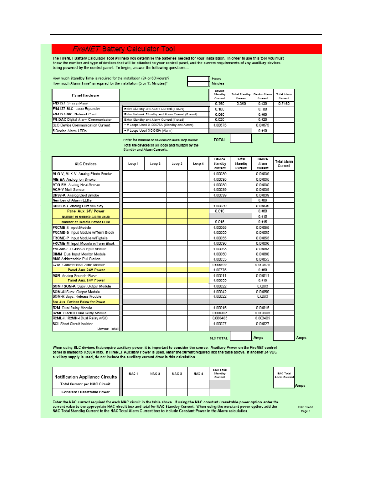
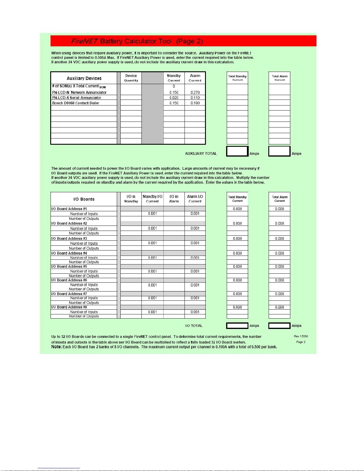
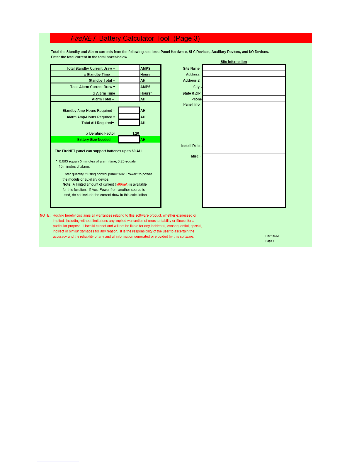
2.6 Battery Calculations
24
FireNET 4127 I & O Manual v1.90 UL
Page 25
25
FireNET 4127 I & O Manual v1.90 UL
Page 26
26
FireNET 4127 I & O Manual v1.90 UL
Page 27
2.7 Electrical Ratings
Table 2.7.1 (X1) Top Terminal Strip Electrical Ratings for Main Control Unit
Terminal # and Label Description
1 - OUT
2 + OUT
3 - IN
4 + IN
5 - OUT
6 + OUT
7 - IN
8 + IN
9 - OUT
10 + OUT
11 - IN
12 + IN
13 - OUT
14 + OUT
15 - IN
16 + IN
17 NC
18 C
19 NO
20 NC
21 C
22 NO
23 NC
24 C
25 NO
26 NC
27 C
28 NO
29 NC
30 C
31 NO
32
+
33
-
34
+
35
-
36
+
37
-
38
+
39
-
SLC 1
SLC 2
SLC 3
SLC 4
Fire 1 Fire condition relay contacts #1.
Trouble Trouble condition relay contacts.
Fire 2 Fire condition relay contacts #2.
Supervisory Supervisory relay contact.
Auxiliary Programmable auxiliary relay contacts.
NAC 1
NAC 2
NAC 3
NAC 4
Signaling Line Circuit. Out terminals used for
Class B or A wiring.
Signaling Line Circuit. In terminals used for
Return Loop for Class A wiring.
Signaling Line Circuit. Out terminals used for
Class B or A wiring.
Signaling Line Circuit. In terminals used for
Return Loop for Class A wiring.
Signaling Line Circuit. Out terminals used for
Class B or A wiring.
Signaling Line Circuit. In terminals used for
Return Loop for Class A wiring.
Signaling Line Circuit. Out terminals used for
Class B or A wiring.
Signaling Line Circuit. In terminals used for
Return Loop for Class A wiring.
Notification Appliance Circuit #1. 10K EOLR
Required.
Notification Appliance Circuit #2. 10K EOLR
Required.
Notification Appliance Circuit #3. 10K EOLR
Required.
Notification Appliance Circuit #4. 10K EOLR
Required.
Voltage Current
32VDC 400mA
32VDC 400mA
32VDC 400mA
32VDC 400mA
32VDC 400mA
32VDC 400mA
32VDC 400mA
32VDC 400mA
32VDC 400mA
32VDC 400mA
32VDC 400mA
32VDC 400mA
32VDC 400mA
32VDC 400mA
32VDC 400mA
32VDC 400mA
30VDC 1 A
30VDC 1 A
30VDC 1 A
30VDC 1 A
30VDC 1 A
30VDC 1 A
30VDC 1 A
30VDC 1 A
30VDC 1 A
30VDC 1 A
30VDC 1 A
30VDC 1 A
30VDC 1 A
30VDC 1 A
30VDC 1 A
24VDC 2.5 A*
24VDC
24VDC
24VDC
24VDC
24VDC
24VDC
24VDC
*Note: See Section 2.8 for additional details regarding NAC circuit ratings
Rating
2.5 A*
2.5 A*
2.5 A*
2.5 A*
2.5 A*
2.5 A*
2.5 A*
27
FireNET 4127 I & O Manual v1.90 UL
Page 28

Table 2.7.2 (X2) Side Terminal Strip Electrical Ratings for Main Control Unit
Terminal # and Label Description
1
+
2
3
+
4
5
+
6
7 TBL
8 RES
9 INT
10 CNT
11 SIL
12 0V
13 PR1
14 PR2
15 PR3
16
+
17
18
+
19
20
+
21
22
+
23
Fire Routing
-
Trouble
-
Routing
Programmable
-
Output
Trouble Input Remote control input 0V 30mA
Reset
Input
Intermittent
Input
Continuous
Input
Silence/Ack
Input
DC Ground
Programmable
Input 1
Programmable
Input 2
Programmable
Input 3
COMMS
-
AUX
-
-
-
24V
NETWORK
IN
NETWORK
OUT
Supervised fire signaling
output
Supervised trouble signaling
output
Supervised programmable
output
Remote control input
Remote control input
Remote control input
Remote control input
Signal for activating remote
inputs
Auxiliary input 0V 30mA
Auxiliary input
Auxiliary input
RS485 to I/O boards 12VDC 100mA
RS485 to I/O boards 12VDC 100mA
Auxiliary 24V supply 24VDC 500mA
Auxiliary 24V supply 24VDC 500mA
RS485 to other panels 12VDC 100mA
RS485 to other panels
RS485 to other panels
RS485 to other panels
Voltage Current
24VDC 500mA
24VDC 500mA
24VDC 500mA
24VDC 500mA
24VDC 500mA
24VDC 500mA
0V 30mA
0V 30mA
0V 30mA
0V 30mA
0V 500mA
0V 30mA
0V 30mA
12VDC 100mA
12VDC 100mA
12VDC 100mA
Rating
28
FireNET 4127 I & O Manual v1.90 UL
Page 29

Table 2.7.3 Terminal Strip Electrical ratings for the Power Supply Module
Connector Terminal Description
TB6 G Earth Ground N/A N/A
N AC Neutral 120 VAC, 50/60Hz 2.1A
240 VAC, 50/60Hz 1.1A
L AC Line 120 VAC, 50/60Hz 2.1A
240 VAC, 50/60Hz 1.1A
TB4 +24VDC + DC Output +24 VDC 0 - 4 Amps
DC RTN - DC Output DC Common 0 - 4 Amps
TB3 + Battery +24 VDC 5A
- Battery DC Common 5A
Voltage Current
Rating
NOTE: Earth ground fault detection impedance is approximately 15K ohms between
earth ground and the FireNET internal floating DC supply.
29
FireNET 4127 I & O Manual v1.90 UL
Page 30

2.8 Specifications
Primary AC: 120VAC @ 2.1 amps 50/60hz (or) 240VAC @ 1.1 amp
50/60hz
Output DC: 24VDC @ 4 amps
Power Supply: 4 amp integrated
Max Charger Current: 1.5 amps
Dimensions: 14.5”W x 24” H x 5”D
Weight: 31 lbs (without batteries)
Color: Red (optional charcoal)
Material: ABS/steel enclosure
Display: 8 line x 40 character LCD (320 characters total)
Network: Dual RS485 ports (64 panels max.)
Zones: 500 network wide software zones per system (Output
zones allocated to zones 1 to 253 only for SOM 2.0 and
earlier)
SLC loops: 2 or 4 (class A or B)
Devices per Loop: 127 sensors & modules, plus 127 analog sounder bases,
254 total
Addresses per Panel (800 addresses + sub-addresses max per panel)
NAC Outputs: (4) 2.5 amp@24VDC (class B)*
Relay Outputs: (5) Form C contact 1amp@30VDC
Voltage Outputs: (3) 500mA@24VDC
Aux. Power: 500mA@24VDC
Aux. Inputs: (8) digital pull downs
PC Port: RS232
Printer Port: RS232
*NOTE: FireNET panels dated 1/24/05 or later with s/n 411-00412
or later have NAC circuits rated at 2.5AMPS each. All
FireNET panels dated earlier than 1/24/05 with s/n prior to
411-00412 have NAC circuits rated at 1.6AMPS each.
30
FireNET 4127 I & O Manual v1.90 UL
Page 31

Section 3 - Power Supply and Main Control Unit Connections
3.1 AC Power Connection
The AC power connection terminals are located in the lower left hand corner of the
power supply module. (See Figure 3.3) Observe the wiring polarity and connect as
shown. Local electrical codes may require that a licensed electrician make these
connections.
NFPA 72 requires that the AC connection be made from a dedicated branch circuit that
is mechanically protected. The circuit must be marked in red and identified as a “FIRE
ALARM CIRCUIT”. The location of the circuit and its disconnecting means shall be
permanently noted at the fire alarm control panel. The circuit breaker must be rated at
20 amps maximum.
Fuse Replacement: To replace the power supply fuse F2, power down the fire system
by removing the AC power first, then disconnect the backup batteries to the fire alarm
control panel. Remove the blown fuse and replace with a 3A 250VAC, slow blow,
5X20mm fuse. When the fuse replacement is completed, restore AC power to the
control panel and connect the back up batteries observing polarity of connections.
3.2 Battery Connection
The FireNET 4127 fire alarm control panel can charge up to 60AH batteries. Up to 17
AH will fit in the control panel enclosure, as well as larger sizes that have the same size
footprint as 17AH batteries. Batteries larger than 17AH may be mounted remotely in the
FN-ACC accessory cabinet. Use the current draw and battery calculation worksheet in
section 2.6 to determine the appropriate size battery to use.
Two battery leads come pre-connected to the power supply module. Connect two 12volt batteries in series to the battery leads as shown in Figure 3.3. Both batteries must
be of the same AH rating. Do not try to parallel multiple batteries together to obtain a
higher AH rating. Use only UL Recognized Sealed Lead Acid Batteries.
Fuse Replacement: To replace the in-line battery fuse, remove the battery lead (RED)
from the positive battery terminal and twist the bayonet fuse holder to open. Remove
the blown fuse and replace with a “Bussman AGC-10” (10A) type fuse or equivalent.
Reassemble bayonet fuse holder and attach the battery lead to the + terminal of the
battery.
NOTE: The standby batteries cannot power the system until the main
120VAC power has been established. Once the system has
been initially powered from them 120VAC source the batteries
will operate the system in the event of a power failure.
31
FireNET 4127 I & O Manual v1.90 UL
Page 32

3.3 Auxiliary Power Connection
24 VDC auxiliary power is available on the main control unit X2 terminal strip from
terminals 18 and 19. (See Figure 3.4) This auxiliary power is intended to run expansion
boards or other low current auxiliary devices.
The total output from the Auxiliary Power terminals must not exceed .500 amps.
Any devices powered from the auxiliary power terminals should be entered into Table
2.6 and taken into consideration for standby battery size.
Figure 3.3 Four-Amp Power Supply Detail
32
FireNET 4127 I & O Manual v1.90 UL
Page 33

Top Terminal Strip
X1
X2
Side Terminal Strip
Main
Control
Unit
ADDITIONAL
I/O BOARDS
+ -
PROGRAMMABLE
REMOTE
CONTROL
AND AUX.
INPUTS
ROUTING
TROUBLE
ROUTING
OUTPUT
1. TBL
2. RES
3. INT
4. CNT
5. SIL
6. PR1
7. PR2
8. PR3
COMMS
NETWORK
FIRE
AUX
24V
IN
+ - + -
NAC 1 NAC 2 NAC 3 NAC 4
+ -
+
-
+
-
+
-
0V
l +
AUX 24VDC Power 500mA Max
Used for expansion boards and
l +
l +
low current auxiliary devices
(See Section A.4 for compatible
24VDC Devices)
NETWORK
OUT
l +
Figure 3.4 Auxiliary Power Connection Detail
33
FireNET 4127 I & O Manual v1.90 UL
Page 34

3.4 Notification Appliance Circuit Connection
• NAC output rated @ 2.5 Amp each.
• See Appendix A.3 for compatible NAC Devices.
• See Section 8 and 9 of this manual for programming.
Class B (Style Y) - For Indicating Devices
X1
Main
Control
Unit
Top Terminal Strip
+ - + -
NAC 1 NAC 2 NAC 3 NAC 4
+ -
CONTROL
PROGRAMMABLE
REMOTE
AND AUX.
INPUT S
FIRE
ROUTING
TROUBLE
ROUTING
OUTPUT
1. TBL
2. RES
3. INT
4. CNT
5. SIL
6. PR1
7. PR2
8. PR3
+ -
+
H/S H/S H/S
-
+
-
+
-
+
-
0V
+
+
-
-
Hochiki America
EOL Device
(EOLD )
P/N 0400-01023
(Supervised)
Figure 3.5 Notification Appliance Circuit Connection Detail
34
FireNET 4127 I & O Manual v1.90 UL
ADDITIONAL
I/O BOARDS
COMMS
AUX
l +
24V
l +
Page 35

3.5 Voltage Routing and Relay Output Connection
3.5.1 Voltage Routing Outputs
• Outputs are fully programmable.
• Outputs are rated @ 500mA Max.
• Outputs are polarity reversing.
• See Appendix A.4 for compatible devices.
• See Section 8 and 9 of this manual for programming.
X2
+ -
NAC 1
Main Control
Unit
+ -
NAC 2 NAC 3 NAC 4
+ -
+ -
ROUTING
TROUBLE
ROUTING
PROGRAMMABLE
OUTPUT
REMOTE
CONTROL
AND AUX.
INPU T S
6. PR1
7. PR2
8. PR3
COMMS
FIRE
1. TBL
2. RES
3. INT
4. CNT
5. SIL
EXAMPLE OF FIRE ROUTING, TROUBLE
ROUTING, & PROGRAMMABLE OUTPUT
+
-
+
-
+
-
0V
l +
POLARITY
REVERSING DEVICE
500 mA @24VDC max.
10K OHM END-OF-LINE RESISTOR (EOLR)
P/N 0400-01046 (Supervised)
1N4004S END-OF-LINE DIODE (EOLD )
P/N 0400-01024 (Supervised)
10K OHM
END-OF-LINE
RESISTOR (EOLR)
P/N 0400-01046
(Supervised)
Figure 3.6 Voltage Routing Outputs Detail
35
FireNET 4127 I & O Manual v1.90 UL
Page 36

3.5.2 Relay Outputs
• Relays are fully programmable except for the supervisory relay.
• The auxiliary relay defaults to reset function that can be used to reset
conventional devices requiring power reset. This inherent function is negated
when the auxiliary is assigned a function.
• Relays are dry form “C” contacts.
• Fire 2 Relay can optionally be programmed as an AC Fail relay with a delay
value.
• See section 8 and 9 of this manual for programming.
Conventional Relay Contacts rated for 1A @ 30VDC.
Main Control
Unit
Must be connected to power limited source.
(Not Supervised) (Resistive)
NC C NO NC C NO NC C NO NC C NO NC C NO
FIRE 1 TROUBLE FIRE 2
Figure 3.7 Relay Outputs Detail
SUPERVISORY
AUXILIARY
+ - + -
NAC 1 NAC 2
36
FireNET 4127 I & O Manual v1.90 UL
Page 37

3.6 Digital Input Connection
• Digital Inputs are fully programmable.
• Digital Inputs are for secondary use only.
• Digital Inputs are pull-down type.
• Digital Inputs are not supervised.
• Digital Inputs are not intended for use with primary initiating devices for fire
conditions.
• These inputs are activated via N.O. dry contact or switch by connecting terminal
12 on X2 to the input.
• See Section 8 and 9 of this manual for programming.
X2
+ -
+ -
NAC 1
NAC 2 NAC 3 NAC 4
Main Control Unit
+ -
PROGRAMMABLE
AND AUX. INPUTS
ROUTING
TROUBLE
ROUTING
OUTPUT
REMOTE
CONTROL
+ -
FIRE
COMMS
1. TBL
2. RES
3. INT
4. CNT
5. SIL
6. PR1
7. PR2
8. PR3
+
-
+
-
+
-
DIGITAL INPUTS
USE DRY CONTACTS ONLY
(EXAMPLE FOR INPUTS 1-8)
0V
l +
(Not Supervised)
Figure 3.8 Remote Control Input Connection Detail
37
FireNET 4127 I & O Manual v1.90 UL
Page 38

3.7 Using a Printer
The FireNET panel will support a local serial printer. The printer connects to the J10
RS-232 port (labeled Printer) on the inside of the front door. J10 is located in the
bottom left-hand corner of the circuit board. The printer cable must be no longer than
20 feet in length. The printer can be used for real-time logging of events. It can also be
used to print the panel’s configuration (see section 8.2.4) or to print the panel’s history
log (see section 10.2.2).
Serial Printer Properties:
• 19.2K Baud
• 8 Bits
• No Parity
• 1-Stop Bit
38
FireNET 4127 I & O Manual v1.90 UL
Page 39

Section 4 – Expander Board Installation
4.1 Compatible Expander Boards
The following Hochiki America Corp. expander boards are listed as compatible with the
FireNET 4127 analog addressable fire alarm system.
Expanders
• FN-4127-SLC - Dual SLC Loop Expander (Local FACP Expander)
• FN-4127-IO – 16 Channel Input/Output Board (RS-485 Bus Device)
• FN-LCD-S Serial LCD Annunciator (RS-485 Bus Device)
This section covers the installation of the devices listed above. For proper operation
each of these devices must be programmed from the FireNET front panel, or by using
the Loop Explorer software. Please refer to Sections 8 and 9 of this manual for more
information on programming the functionality of expander boards.
39
FireNET 4127 I & O Manual v1.90 UL
Page 40

4.2 General Installation of RS-485 Bus Devices
4.2.1 Wiring Distance and Mounting Locations
RS485 bus devices can be mounted either in the main control panel on the standoffs
provided to the right of the control unit, or in an accessory cabinet (FN-ACC). When
mounting remotely in an accessory cabinet the distance from the panel to the RS485
bus device must not exceed 4000 feet. A suitable communications cable for RS485
applications must be used for the RS485 bus devices.
Specific wiring connections for each device are included later in this section. For
specific wiring distance, connections, and mounting of the FN-LCD-S serial LCD
Annunciator, see Section 4.7.
40
FireNET 4127 I & O Manual v1.90 UL
Page 41

4.2.2 Addressing
Up to 32 RS485 bus devices can be added to the system. Each RS485 bus device
must be set to a unique address 1-32.
The address for each RS485 bus device is set using a position DIP-switch in binary
fashion. Switches 1-5 represent the values 1, 2, 4, 8, and 16, respectively. Switch 6 is
not used. To set the address, move only the switches whose values when added equal
the address value you wish to set, to the “ON” position. For example moving switches 1
and 3 (whose values are 1 and 4 respectively) to the “ON” position sets the address of
5 into the RS485 bus device. See the other examples below:
ADDRESS 1
Addresses must be set with no power applied to the system.
ADDRESS 5
ADDRESS 21
Switch Number – 1 2 3 4 5 6
Value – 1 2 4 8 16 not used
4.2.3 Terminating
The last board connected to the RS485 bus must have a
terminating jumper installed at position J3 as shown in figure
4.2.3.1
Even if only 1 RS485 bus device is connected to the panel this
jumper must be installed.
Jumper J3
1
L
J1
C3
6
5
4
2
2
2
R
R
R
LED1
3
2
R
1
2
W
LED2
2
S
R
1
LED3
2
R
+
RX TX
X2
COMMS ININ
0V
V
7
4
2
0V
9
2
2
R
R
+
C2
+
C1
U1
9
1
R
0
2
R
J2 J3
0
3
R
4
3
R
1
R
T
X
4
5
TR1
S1
R
6
3
U7
R
7
2
8
3
3
2
R
R
R
U6
1
3
3
3
R
R
1
F
D1
U5
C7
D17
+
Figure 4.2.3.1
0
0V0V
1
C
1
1
C
0V
V
OUTCOMMS OUT I/O
-
SD1
+
J4
8
3
R
0V RX TX 24
C9
C6
+
5
3
R
C8
+
L1
41
FireNET 4127 I & O Manual v1.90 UL
Page 42

4.2.4 Power Connections
All RS485 bus devices require 24 VDC to operate. The AUX 24V terminals of the FN4127 can supply this voltage (500 milliamps maximum) or you may use an external
power supply that provides 24 VDC output.
Connections are provided on each RS485 bus device for both incoming and outgoing
power.
4.2.5 COMMS Connection
In addition to power, each RS485 bus device requires a pair of conductors for data
communication. This wiring is connected to the COMMS + and - terminals on the FN4127 control panel or can be connected to the COMMS OUT + and - terminals of
another RS485 bus device.
ADDITIONAL
I/O BOARDS
+ -
FIRE
ROUTING
TROUBLE
ROUTING
PROGRAMMABLE
OUTPUT
REMOTE
CONTROL
AND AUX.
INPUTS
COMMS
AUX
24X
NETWORK
NETWORK
OUT
1. TBL
2. RES
3. INT
4. CNT
5. SIL
6. PR1
7. PR2
8. PR3
IN
+ -
+
-
+
-
+
-
0V
l +
l +
l +
l +
J1
C3
6
5
4
2
2
2
R
R
R
LED
3
1
2
R
LED
W
1
2
S
2
2
R
LED
1
2
3
R
+
RX
X2
COMMS ININ
0V
V
7
4
9
2
2
2
R
R
0V
+
C2
+
C
1
U1
9
1
R
0
2
R
J2 J3
0
3
R
4
3
R
1
R
0
0V0V
1
C
1
L
T
X
1
1
C
4
5
TR1
S1
R
6
3
SD1
U7
R
J4
8
8
7
2
3
2
3
3
R
R
R
R
U6
1
3
5
3
3
3
R
R
R
1
F
D1
U5
C7
L1
D17
+
TO NEXT I/O
BOARD
OUTCOMMS OUT I/O
24V 0V
T
X
-
+
0V RX
C9
C6
+
C8
+
+ - + -
NAC 1 NAC 2 NAC 3 NAC 4
42
FireNET 4127 I & O Manual v1.90 UL
Page 43

4.3 FN-4127-IO - Input / Output Board
In addition to the basic 508 points that the FireNET 4127 can accommodate on the SLC
loops additional input and output points can be added by using FN-4127-IO
Input/Output boards on the RS485 bus.
The FN-4127-IO has 16 channels. Each channel can be individually configured as
either an input or an output. Up to 32 FN-4127-IO boards can be connected to the
system via the RS485 bus giving the system an additional 512 inputs/outputs.
4.3.1 Configuring Inputs
Inputs to the FN-4127-IO are optically
isolated and connected to the board by
installing a normally open contact with a
resistance no greater than 500 ohms to
any input and a terminal marked 0V. The
current switched by the contact will be a
maximum of 3 milliamps.
NOTE: Inputs on the I/O board are not supervised. These inputs are not
for primary initiating or detection of fire or life safety conditions.
These inputs are for programmable for secondary use only, and
not used for signaling Fire, Supervisory, or Trouble conditions. All
primary initiating or detection inputs must be connected to
applicable SLC devices listed for fire. See Section 5 of this manual
for SLC devices.
43
FireNET 4127 I & O Manual v1.90 UL
Page 44

4.3.2 Configuring Outputs
When configured as outputs, the I/O board channels supply a negative voltage (with
respect to the I/O board 24V power supply) via a transistor.
Because transistor elements can be damaged by excessive current drain, great care
should be taken when connecting to outputs. Particular care should be taken to ensure that
suppression diodes on relay coils are correctly polarized. Wrongly connected diodes will
damage the outputs. Diodes
should be connected with the
band to the positive 24V.
Individual channels can supply
current up to 100 milliamps but
this must be limited to 500
milliamps for each bank of
eight (500 milliamps for 1-8
and 500 milliamps for 9-16).
The power supply to the I/O
board should also be
considered to ensure that its
rating is not exceeded if
multiple channels are switched
on. Overall current draw for the
I/O board is 1010mA max.
NOTE: Outputs on the I/O board are not supervised. These outputs are
not for primary notification of fire conditions (i.e. not for use as NAC
circuits). These outputs are for secondary use only. All primary
notification output devices must be connected to applicable NAC
circuits on the FireNET panel. See Section 3.4, Appendix A, and B
for details on NAC circuits and compatible NAC devices.
When powering the I/O board from the FireNET Aux 24VDC power (limited to 500ma), the
following maximum wiring distances apply at the gauges noted:
Wire
Distance
18AWG 875ft
16AWG 1400ft
14AWG 2300ft
When powering the I/O board from a separate Aux 24VDC UL Fire listed supply the
maximum voltage drop cannot exceed 4VDC.
2.2k
44
FireNET 4127 I & O Manual v1.90 UL
Page 45

4.3.3 LED Indicators
LED indicators on the I/O board give some simple diagnostic information
and show that the boards are communicating with the control panel. The
red LED (LED1) is on during receipt of a message from the control panel
and will turn off if the I/O board feels the communication is normal.
• If the LED is flickering more or less continuously - the board is
operating normally.
• If this LED is not lit - the board is not receiv ing data from the
control panel and the comms connection should be checked.
• If this LED is permanently lit - then it is likely that data is being
received but that it is being corrupted. In this case the quality of
the comms connection should be checked for interference from
mains or other noise generating sources.
The yellow LED (LED2) will flicker briefly every few seconds when the I/O
board responds to the main panel. If this LED does not flicker then it is
not responding to the control panel and the comms connection should be
checked.
LED 1
LED 2
C12
+
C13
+
COMMS IN
N
I
R40
R42
R44
R18
OP4
D10
R43
R45
R39
R41
U4
R46
R48
R50
R52
OP3
R47
R49
R51
R53
R2
R4
R6
R8
OP1
SERIAL NUMBER
1
0
E
U
S
S
K6006
I
J1
SW1
RX TX
X2
0V
V
4
2
0V
R3
R5
R7
R9
U3
R10
R12
R14
R16
OP2
R11
R13
R15
R17
U1
C3
6
9
5
4
2
1
2
2
S1
R
R
R
R
LED1
0
3
2
2
U7
R
R
2
LED2
2
J2 J3
R
1
7
0
2
LED3
2
3
3
3
R
R
R
R
1
7
9
4
3
2
2
3
R
R
R
R
+
R1
C2
D1
+
U5
C1
D17
+
1
D11
2
C4
3
D12
4
D13
5
D14
6
D15
7
D16
L
E
8
D18
N
N
X1
A
H
9
D2
C
O
/
I
D3
D4
C5
D5
D6
D7
D8
D9
0
0V0V 16 15 14 13 12 11 10
1
C
1
L
T
X
1
1
C
0V
T
U
V
O
4
2
TR1
R54
6
3
SD1
R
0V RX TX
COMMS OUT I/O
J4
8
8
3
C9
2
C6
R
R
+
U6
3
5
3
3
R
R
C8
F1
+
C7
L1
4.4 Reserved for Future Use
4.5 Reserved for Future Use
45
FireNET 4127 I & O Manual v1.90 UL
Page 46

4.6 FN-4127-SLC – Dual SLC Loop Expander
The FN-4127 FireNET control panel is provided with two SLC Loops, however an
additional two SLC Loops may be added at the factory or a later date if required
through the use of a FN-4127-SLC expander board.
The main control unit has terminations for connecting all four SLC loops, but on the
basic 2-loop control panels not using an SLC loop expander there is no circuitry for
SLC loops 3 & 4. The FN-4127-SLC dual loop expander board adds circuitry for loops 3
& 4.
4.6.1 Installation of the FN-4127-SLC
1. To install the additional SLC Loops, the control panel must have its 120V AC line
and battery power removed.
2. The metal cover on the terminal board should be removed by loosening the
single screw in the center of the cover.
3. The circuit board containing the additional loop circuits is supplied in a static
dissipative bag and should remain in this bag until it is to be installed.
NOTE: As with all electronic components, this circuit board is very sensitive and
can be easily damaged by electrostatic discharge.
4. The loop board mounts on the left hand side of the terminal board and fits upside
down compared with the existing circuit. The additional 2-loop circuit board is
supplied with 2 ribbon cables of different sizes and the board should be oriented
so that the ribbon cables match the connectors.
5. Install the four mounting standoffs to the main board, then attach the additional
2-loop board using the M3 screws and fiber washers.
6. After checking that the new circuit board is properly installed and making good
contact with its connectors, the metal cover should be replaced. Connect the
SLC loop wiring, then re-apply power to the control panel.
7. Unused detection circuits must have the "loop + out" to "loop + in" and "loop out" to "loop - in" terminals wired together to prevent open circuit troubles from
being reported. Class B SLC circuits also require the 0 ohm jumpers to be
installed – please see Section 5.3.1.
Once the detection circuits have been connected, the devices for the new detection
circuits can be automatically detected using the auto learn feature from the menu on
the control panel (see Section 8 of this manual).
46
FireNET 4127 I & O Manual v1.90 UL
Page 47

4
4.7 FN-
L
L
n
C
s
s
S
a
L
n
a
p
.
w
a
S
a
s
c
o
e
a
p
F
4
e
u
t
t
t
t
u
n
L
o
-
n
o
e
a
n
m
r
A
b
7
t
u
n
a
v
s
t
m
h
h
u
e
C
g
W
a
h
e
M
r
e
o
o
7
2
e
e
n
a
a
n
e
n
c
h
o
w
m
1
N
4
o
e
o
o
.
w
o
e
e
e
o
o
CD-S
erial Liq
id Crys
al Displ
y Annun
ciator
The FNalarm co
buss that
15 FN-L
4.7.1 In
Refer to
FN-LCDin an are
The FNwall. Use
the annu
For oper
LCD-S o
controls.
Figure 4
When po
an extern
distances
CD-S Seri
trol panel
is designa
D-S units
tallation
ection 2.2
should b
in compli
CD-S may
a suitable
ciator.
tions and
erates in t
7.2 FN-LC
ering the
l UL864/1
apply to th
Wire R
1000 f
2000 f
3000 f
4000 f
l LCD An
. The FN-
ted “Additi
an be con
f the FN
of this ma
mounted
nce with l
be surfac
standoff m
rogrammi
he same
D-S Serial
N-LCD-S f
81 Listed
power ca
n
. 6
. 3
. 2
. 1
unciator d
CD-S con
nal I/O bo
nected via
LCD-S
ual for en
so that it i
cal regula
or flush
terial suc
g, refer to
anner as t
LCD Ann
om the Fir
UX 24VD
les at the
20
plicates t
ects to th
rds – CO
RS485 se
ironmental
accessibl
ions.
ounted. D
as plywo
Sections
e main pa
nciator
NET Aux
supply, th
auges not
ire AWG
18
9
4
3
2
e indicatio
control p
ial port to
installatio
to servic
d to keep
and 8 of t
nel operat
4VDC po
following
d:
16
15
7
5
3
MS” on th
not mou
14
15
12
8
6
s of the F
nel via RS
e K6002 b
single Fir
specificat
personnel
t directly t
ondensati
is manual
r interface
er (limited t
aximum
-4127 fire
85 serial
ard. Up t
NET pan
ions. The
and locat
a concret
n away fr
The FN-
and
o 500mA)
iring
l.
d
m
r
FireNET
127 I & O
Manual
4
v
.90 UL
Page 48

Figure 4.7.3 FN-LCD-S Wiring Detail
48
FireNET 4127 I & O Manual v1.90 UL
Page 49

NOTE: When connecting I/O boards to the FN-LCD-S via the COMMS
terminals shown above, the I/O boards must be powered by a
UL864/1481 listed local Auxiliary 24VDC power supply, or the Aux
24VDC output of the FN-LCD-S within the limits outlined below.
DO NOT
FN-LCD-S unless
24VDC output rating of the FN-LCD-S and
connect the I/O board power input to the Aux 24VDC output terminals of the
the sum current load of the I/O board is within the 500mA max
within the 500ma max 24VDC output rating
of the FN-4127 control panel that provides power to the FN-LCD-S. Failure to make
this consideration may result in overloading the FN-LCD-S and/or the control panel
Aux 24VDC output (500ma max. each).
The current limits during both standby and in alarm shall not exceed the 500mA rating
of the FN-4127 Panel Aux 24VDC output or FN-LCD-S.
The FN-LCD-S current draw is rated as follows:
Standby
Alarm
: 20mA @ 24VDC
: 110mA @ 24VDC
Available colors are RED and CHARCOAL as identified below:
FN-LCD-S-R = RED
FN-LCD-S-C = CHARCOAL
49
FireNET 4127 I & O Manual v1.90 UL
Page 50

Section 5 – SLC Device Installation
5.1 Compatible SLC Devices
The following Hochiki America Corp. SLC devices are listed as compatible with the
FireNET 4127 analog addressable fire alarm system.
Detectors (Sensors)
• ALK-V / ALK-V2 Anal og Photoelectric Smoke Detector
•
ALG-V Analog Photoelectric Smoke Detector
•
AIE-EA Analog Ionization Smoke Detector
•
ATG-EA Analog Heat Detector
•
ACA-V Analog Photoelectric and Heat Multi Detector
•
DH98-A Analog Duct Smoke Detector, no Relay
• DH98-AR Analog Duct Smoke Detector with Relay
Smoke sensors will undergo automatic sensitivity testing and verification every 24
hours.
Modules
•
DCP FRCME-4 Addressable Input Module
• DCP FRCME-S, FRCME-M Mini Addressable Input Module (with Terminal Blocks)
• DCP FRCMA Class A Addressable Input Module
• DCP FRCMA-I Class A Addressable Input Module (with SCI)
•
DCP R2M, R2ML, R2MH Addressable Dual Relay Module
• DCP R2ML-I, R2MH-I Addressable Dual Relay Module (with SCI)
• DCP SOM Addressable Supervised Output module
• DCP SOM-A Addressable Class A Supervised Output Module
• DCP SOM-AI Addressable Class A Supervised Output Module (with SCI)
• DCP SCI Short Circuit Isolator
• DCP DIMM Dual Input Monitor Module
50
FireNET 4127 I & O Manual v1.90 UL
Page 51

• CZM Conventional Zone Module
• ASB Analog Sounder Base
• DCP AMS Addressable Manual Pull-Station
• SOM-R Addressable Supervised Output Module (Preaction Sprinkler Systems)
NOTE: The “DCP” prefix listed above on several devices indicates the device’s formal
model name as specified by Underwriters Laboratories within each device’s
individual listing. The “DCP” prefix will be dropped throughout the body of this
manual and the shortened model name will be used. Please take note of this
when referencing these devices within this manual.
51
FireNET 4127 I & O Manual v1.90 UL
Page 52

5.2 Number of Devices
The FireNET 4127 comes with 2 SLC loops built-in to the panel. Each loop can support
up to 127 analog addressable detectors and modules as well as 127 analog sounder
bases for a total of 254 possible per loop. By adding the FN-4127-SLC expander card,
2 additional SLC loops can be added to the panel for a total of 4 loops.
Addresses 1 – 127 are reserved for any combination of detectors and modules.
Addresses 128 – 254 are reserved for analog sounder bases. Detectors and modules
cannot be addressed to the upper address 128 - 254. Each device on the SLC loop
must have a unique address. Refer to section 5.4 for instructions on programming the
address into each analog addressable device.
5.3 SLC Loop Wiring
The FireNET 4127 uses the patented Hochiki DCP Digital Communication Protocol to
communicate with each of the analog addressable devices located on the SLC loops.
This extremely fast and reliable protocol allows the use of standard non-twisted, nonshielded wiring for the SLC loops.
The SLC loop wiring may be any solid or stranded cabling that meets the requirements
for power limited fire protective signaling circuits listed in NFPA 70 (National Electrical
Code) Article 760. The wiring resistance on the SLC loop must be less than 50 ohms.
Loop capacitance must be less than 1
The SLC loop terminals are located on the upper left hand corner of the main control
board. See Figure 5.3.
1 2 3 4 5 6 7 8 9 10 11 12 13 14 15 16
μF. Loop inductance must be less than 1mH.
-
-
+
OUT
LOOP 1 LOOP 2 LOOP 3 LOOP 4
OUT
-
+
+
IN
52
FireNET 4127 I & O Manual v1.90 UL
-
-
+
+
+
IN
OUT
MAIN CONTROL UNIT
IN
OUT
-
+
+
IN
Figure 5.3 SLC Loop Terminals
Page 53

5.3.1 Class B SLC Loop Wiring Distance
Refer to Figure 5.3.1 to determine the maximum distance an analog addressable
detector or module is allowed to be located from the control panel for Class B SLC
loops. The total wire length of all branches of the SLC loop must not exceed 40,000
feet using #14 AWG. When using a Class B SLC wiring configuration, be sure that the
0 ohm jumpers supplied with the panel are properly installed between –OUT to –IN and
+OUT to +IN (Hochiki part # 0400-01025).
Figure 5.3.1 Maximum Wiring Distance for Class B SLC Circuits
53
FireNET 4127 I & O Manual v1.90 UL
Page 54

5.3.2 Class A SLC Loop Wiring Distance
Refer to Figure 5.3.3 to determine the maximum distance an analog addressable
detector or module is allowed to be located from the control panel for Class A SLC
loops.
Class A
Style 6 or 7
SLC Loop
NOTE: For Details on Style 7, refer to Section 5.14.1
Calculate t otal loop length out and
back to determine appropriate
wire gauge for Class A SLC loops
Wire Guage
Maximum Wire Length From Control Panel
Out and Back to Control Panel
18 AWG 3900 Feet
16 AWG 6200 Feet
14 AWG 10,000 Feet
1 2 3 4 5 6 7 8 9 10 11 12 13 14 15 16
-
-
+
1 2 3 4 5 6 7 8 9
OUT
LOOP 1 LOOP 2 LOOP 3 LOOP 4
-
-
+
+
IN
OUT
-
+
IN
MAIN CONTROL UNIT
OUT
-
-
OUT
-
+
+
IN
+
+
IN
Figure 5.3.2 Maximum Wiring Distance for Class A SLC Circuits
54
FireNET 4127 I & O Manual v1.90 UL
Page 55

Additional Notes Regarding Class A Style 6 and Style 7 SLC loops:
• No t-taps are allowed on Class A SLC loops.
• The return side of the loop must be routed separately from the outgoing loop.
• The return side may not share the same conduit or cable as the outgoing side of
the SLC loop.
• When using Class A Style 7 wiring, the SCI Short Circuit Isolator must be
installed before and after each analog addressable device on the SLC loop. The
wiring from the control panel to the first SCI and from the last SCI back to the control
panel must be in conduit. Refer to Section 5.14 for more information on installing
the SCI module and for installation method to satisfy Style 7 criteria per NFPA 72.
• Refer to NFPA 72 for additional requirements of Class A circuits.
5.4 Addressing Devices
Prior to installation, all of the addressable devices installed on each of the FireNET
4127 SLC loops must be programmed with a unique address ranging from 1 to 127.
The analog sounder bases will automatically derive their address from the host sensor
(detector) attached to them. The ASB address will be the sensor address + 127 (i.e. N
+ 127). Example: The sensor address is 36. 36 +127 = 163. The ASB will have an
address of 163. This address is what the FireNET 4127 control panel uses to identify
each addressable device and control its functionality. All Hochiki addressable devices
come from the factory preset to address 127. This preset address can be
reprogrammed using the Hochiki TCH-B100-NS programmer. Follow these instructions
to set/reprogram the address.
1. Identify each analog addressable device that will be installed on an SLC loop
and label it with a unique address ranging from 1 to 127.
2. Using the Hochiki TCH-B100-NS programmer as shown in Figure 5.4, program
the appropriate address into each analog addressable device.
55
FireNET 4127 I & O Manual v1.90 UL
Page 56

Figure 5.4 Hochiki TCH-B100-NS Programmer Connections
1. ASB Automatically derives its address from host sensor (N + 127).
2. Devices must not be powered when using the TCH-B100-NS programmer to set
addresses.
3. Mini-modules such as the FRCME-S and FRCME-P should not be connected to
the SLC loop when using the TCH-B100-NS programmer to set addresses.
4. When programming the AMS, use the same method as the 4-S type
addressable modules.
56
FireNET 4127 I & O Manual v1.90 UL
Page 57

5.4.1 Detector Addressing
This section applies to the following Hochiki analog detectors – ALK-V, ALK-V2, ALGV, AIE-EA, DH-98, ATG-EA, and ACA-V. Follow these steps to program a new address
into any one of these analog detectors. (Refer to Figure 5-4)
1. Twist an analog detector head on to the programmer terminals.
2. Press the left gray button to turn on the programmer and read/display the current
address in the detector head. (Factory default is address 127)
3. Using the left gray button you can increase the tens digit one number at a time.
Using the right gray button you can increase the ones digit one number at a
time. Using these buttons change the displayed address to the appropriate
value.
4. Press the red button to store the displayed address into the detector head.
5.4.2 4-S Module and AMS Addressing
This section applies to the following Hochiki addressable modules - FRCME-4, FRCMA,
FRCMA-I, R2M (all models), DIMM, CZM, SOM (all models), and AMS. Follow these
steps to program a new address into any of these addressable modules. (Refer to
Figure 5-4)
1. Using the dual-end programming plug provided with the programmer, plug one
end into the jack on the programmer and plug the other end into the
programming plug located on the front of the module plate. The plug is nonpolarized and can be connected in either orientation.
2. Press the left gray button to turn on the programmer and read/display the current
address in the module.
3. Using the left gray button you can increase the displayed address 10 numbers at
a time. Using the right gray button you can increase the displayed address one
number at a time. Using these buttons change the displayed address to the
appropriate value.
4. Press the red button to store the displayed address into the addressable module.
57
FireNET 4127 I & O Manual v1.90 UL
Page 58

5.4.3 Mini Module Addressing
This section applies to the Hochiki FRCME-S, FRCME-P and FRCME-M addressable
mini-module. Follow these steps to program a new address into any of these
addressable modules. (Refer to Figure 5-4)
1. Using the single ended programming plug, plug the end with the jack on it into
the programming jack on the programmer. The programming plug with alligator
clips may also be used.
2. Connect the Red wire of the single ended programming plug into the terminal
labeled
ended programming plug into the terminal labeled
module.
3. Press the left gray button to turn on the programmer and read/display the current
address in the module.
4. Using the left gray button you can increase the displayed address 10 numbers at
a time. Using the right gray button you can increase the displayed address one
number at a time. Using these buttons change the displayed address to the
appropriate value.
5. Press the red button to store the displayed address into the addressable module.
S (IN) on the addressable module. Connect the Black wire of the single
SC (IN) on the addressable
58
FireNET 4127 I & O Manual v1.90 UL
Page 59

5.5 Smoke and Heat Detector Wiring
This section includes wiring instructions for connecting the following analog detectors to
the FireNET 4127 fire alarm control panel: ALK-V / ALK-V2 Photoelectric Smoke
Detector, ALG-V Photoelectric Smoke Detector, AIE-EA Ionization Smoke Detector,
ATG-EA Heat Detector, ACA-V Multi Detector. All FireNET analog detectors must be
installed using a YBN-NSA-4 four-inch detector base, or a HSB-NSA-6 six-inch detector
base.
For detailed instructions on the physical mounting of FireNET analog smoke and heat
detectors please refer to the installation instructions that are included with each analog
detector.
Prior to installing any analog detector or module you must set its address as described
in section 5.4.
Wire the analog smoke and heat detector bases as indicated in Figure 5.5.
1 2 3 4 5 6 7 8 9
-
-
-
+
OUT
LOOP 1 LOOP 2 LOOP 3 LOOP 4
-
+
+
IN
OUT
MAIN CONTROL UNIT
10 11 12 13 14 15 16
-
+
+
IN
OUT
3
56
4
1
2
3
56
4
1
2
-
+
YBN-NSA-4 Four Inch Detector Base Shown
Follow same instructions for HSB-NSA-6 Six Inch Base
-
-
-
+
+
OUT
+
IN
IN
To next SLC detector
or module
Figure 5.5 Analog Detector Base Wiring
59
FireNET 4127 I & O Manual v1.90 UL
Page 60

5.6 Analog Duct Detector Wiring
This section includes wiring instructions for connecting the DH98-A analog duct
detector, and the DH98-AR analog duct detector with relay, to the FireNET 4127 control
panel SLC loop.
For detailed instructions on the physical mounting and wiring of FireNET analog duct
detectors please refer to the installation instructions that are included with each device.
Prior to installing any analog detector or module you must set its address as described
in section 5.4. You will need to remove the smoke detector head from the base in the
duct detector in order to program it.
60
FireNET 4127 I & O Manual v1.90 UL
Page 61

Duct Detector Model #
Operating Voltage
Detector Head Model
Detector Head Type
Sensitivity Test Method
DH98-A
DCP Powered Loop
ALG-V
Analog Photoelectric
Control Panel
1122334
4
To next SLC device
-
+
+
-
1 2 3 4 5 6 7 8 9
-
-
-
+
+
OUT
IN
OUT
LOOP 1 LOOP 2 LOOP 3 LOOP 4
10 11 12 13 14 15 16
-
-
-
-
+
+
+
IN
OUT
-
+
+
IN
OUT
MAIN CONTROL UNIT
+
IN
Remote LED 24 VDC
@ .008 amps max
Figure 5.6.1 DH98-A
5.6.1 DH98-A Analog Duct Detector
Connect the DH98-A analog duct detector to the FireNET 4127 control panel SLC loop
as shown in Figure 5.6.1.
Terminals 3 and 4 can be used to power a remote alarm LED. The ratings on these
terminals are 24 VDC at .008 amps maximum. Please note the number of alarm LED’s
that can be illuminated at one time is limited to 5 addresses per SLC loop by the control
panel.
NOTE: The duct sensor LED and remote LED output only activate momentarily when
in alarm.
61
FireNET 4127 I & O Manual v1.90 UL
Page 62

Duct Detector Model #
Operating Voltage
Detector Head Model
Detector Head Type
Sensitivity Test Method
1 2 3 4 5 6 7 8 9 10 11 12
L2 +24V 0V +REM LED- NC C NO NC C NO
L1
DH98-A
DCP Powered Loop
ALG-V
Analog Photoelectric
Control Panel
To 24VDC auxiliary power
from control panel or
external power supply.
24VDC Power is not
Supervised. An EOL Relay
-
must be used at the end of
+
line. The EOL relay must be
monitored for power loss
trouble.
-
To next SLC device
+
K1 K2
1 2 3 4 5 6 7 8 9
-
-
-
+
+
OUT
IN
OUT
LOOP 1 LOOP 2 LOOP 3 LOOP 4
10 11 12 13 14 15 16
-
-
-
-
+
+
+
IN
OUT
-
+
+
IN
OUT
IN
MAIN CONTROL UNIT
Relays for fan
+
shutdown and au xilia ry
functions rated at
10.0A @ 250VAC
Figure 5.6.2 DH98-AR
5.6.2 DH98-AR Analog Duct Detector with Relay
Connect the DH98-AR analog duct detector with relays, to the FireNET 4127 control
panel as shown in Figure 5.6.2.
In addition to the SLC loop connections, the DH98-AR requires 24-volt reset-able
auxiliary power (10mA standby and 55mA alarm) connected to terminals 3+ and 4-.
This power may come from the FireNET 4127 main control panel auxiliary power (500
mA max.) connections (terminals 18 and 19) or from an external power supply.
The DH98-AR analog duct detector contains 2 sets of form C alarm contacts rated at
10.0 amps @ 250 VAC that can be used for fan shutdown and other auxiliary functions.
In addition to the alarm contacts the DH98-AR also has connections for a remote test
switch as well as outputs for a remote alarm and remote pilot light LED’s.
NOTE: Test switch only activates output relays, and does not
place the detector into alarm.
62
FireNET 4127 I & O Manual v1.90 UL
Page 63

5.7 FRCME-4 Input Module Wiring
The FRCME-4 input module is used to connect standard normally open dry contact
types of fire alarm devices such as pull stations, waterflow, or tamper switches to the
FireNET 4127 SLC loop. More than one switch can be connected to a FRCME-4
however you must not mix multiple switch types on a single FRCME-4.
three waterflow switches connected to a single FRCME-4 is acceptable. However, two
waterflow switches and one valve tamper switch connected to a single FRCME-4 is not.
NFPA and local codes may also apply.
The FRCME-4 must be programmed with a unique address from 1-127. All of the
switches connected to a single FRCME-4 appear at the main control panel as a single
address. Please refer to section 5.4 of this manual for instructions on programming an
address into the FRCME-4 input module.
Connect the FRCME-4 to the FireNET as shown in figure 5.7.1. Refer to the installation
instructions included with the FRCME-4 for more detailed installation and wiring
instructions.
UL Listed EOLR
(10K OHM)
Part # 0400-01046
For example:
To next SLC Device
S5694
R
U
IN-B
-
+
1 2 3 4 5 6 7 8 9 10 11 12 13 14 15 16
-
-
-
-
-
+
+
+
+
OUT
IN
OUT
IN
LOOP 1 LOOP 2 LOOP 3 LOOP 4
-
+
+
OUT
IN
MAIN CONTROL UNIT
IN-A
SC -
S +
-
-
+
OUT
IN
+
L
Underwriters
Laboratories Inc.
FRCME-4
Figure 5.7.1 FRCME-4 Input Module Wiring Detail
63
FireNET 4127 I & O Manual v1.90 UL
Page 64

5.8 FRCME-S Mini Input Module (w/ Terminal Blocks)
The FRCME-S input module is used to connect standard normally open dry contact
types of fire alarm devices such as manual pull stations to the FireNET 4127 SLC loop.
The FRCME-S must be programmed with a unique address from 1-127. All of the dry
contact type devices connected to a single FRCME-S appear at the main control panel
as a single address. Please refer to section 5.4 of this manual for instructions on
programming an address into the FRCME-S input module.
Connect the FRCME-S to the FireNET as shown in figure 5.8.1. Refer to the installation
instructions included with the FRCME-S for more detailed installation and wiring
instructions.
UL Listed EOLR
(10K OHM)
Part # 0400-01046
S5694
R
U
L
Underwriters
Laboratories Inc.
FRCME-S
To next SLC Device
IN-B
-
+
1 2 3 4 5 6 7 8 9 10 11 12 13 14 15 16
-
-
-
-
-
+
+
+
+
OUT
IN
OUT
IN
LOOP 1 LOOP 2 LOOP 3 LOOP 4
-
+
+
OUT
IN
MAIN CONTROL UNIT
IN-A
SC
-
-
+
OUT
IN
S
+
Figure 5.8.1 FRCME-S Mini Input Module (w/ Terminal Blocks) Detail
th
NOTE: The FRCME-S is approved to UL 864 8
th
operate with the 9
edition approved FireNET Fire Alarm Control panel. Therefore, it
edition. However, the FRCME-S will
may be used in panel retrofit applications, subject to approval by your AHJ.
64
FireNET 4127 I & O Manual v1.90 UL
Page 65

5.9 FRCME-P Mini Input Module (w/ Pigtails)
The FRCME-P input module is used to connect standard normally open dry contact
types of fire alarm devices such as manual pull stations to the FireNET 4127 SLC loop.
The FRCME-P must be programmed with a unique address from 1-127. All of the dry
contact type devices connected to a single FRCME-P appear at the main control panel
as a single address. Please refer to section 5.4 of this manual for instructions on
programming an address into the FRCME-P input module.
Connect the FRCME-P to the FireNET as shown in figure 5.9.1. Refer to the installation
instructions included with the FRCME-P for more detailed installation and wiring
instructions.
UL Listed EOLR
(10K OHM)
Part # 0400-01046
White
S5694
R
U
L
Underwriters
Laboratories Inc.
FRCME-P
To next SLC Device
IN-B
IN-A
SC (IN)
+
SC (OUT)
S (IN)
S (OUT)
Black
Red
1 2 3 4 5 6 7 8 9 10 11 12 13 14 15 16
-
-
-
-
-
-
-
+
+
+
+
+
OUT
IN
OUT
IN
LOOP 1 LOOP 2 LOOP 3 LOOP 4
+
OUT
IN
MAIN CONTROL UNIT
-
+
+
OUT
IN
Figure 5.9.1 FRCME-P Mini Input Module (w/ Pigtails) Detail
th
NOTE: The FRCME-P is approved to UL 864 8
th
operate with the 9
edition approved FireNET Fire Alarm Control panel. Therefore, it
edition. However, the FRCME-P will
may be used in panel retrofit applications, subject to approval by your AHJ.
65
FireNET 4127 I & O Manual v1.90 UL
Page 66

5.10 FRCME-M Mini Input Module (w/ Terminal Blocks)
The FRCME-M input module is used to connect standard normally open dry contact
types of fire alarm devices such as manual pull stations to the FireNET 4127 SLC loop.
The FRCME-M must be programmed with a unique address from 1-127. All of the dry
contact type devices connected to a single FRCME-S appear at the main control panel
as a single address. Please refer to section 5.4 of this manual for instructions on
programming an address into the FRCME-M input module.
Connect the FRCME-M to the FireNET as shown in figure 5.10.1. Refer to the
installation instructions included with the FRCME-M for more detailed installation and
wiring instructions.
Figure 5.10.1 FRCME-M Mini Input Module (w/ Terminal Blocks) Detail
66
FireNET 4127 I & O Manual v1.90 UL
Page 67

5.11 FRCMA / FRCMA-I Input Module
The FRCMA / FRCMA-I input module is used to connect standard normally open dry
contact types of fire alarm devices such as manual pull stations to the FireNET SLC
loop. The FRCMA module provides one class A or one class B input circuit. The
FRCMA-I includes built-in short circuit isolation for the SLC loop.
The FRCMA must be programmed with a unique address from 1-127. All of the dry
contact type devices connected to a single FRCMA are displayed at the main control
panel as a single address. Please refer to section 5.4 of this manual for instructions on
programming an address into the FRCMA input module.
Connect the FRCMA to the FireNET as shown in figure 5.11.1. Refer to the installation
instructions included with the FRCMA for more detailed installation and wiring
instructions.
DCP-FRCMA-I
To next SLC Device
-
+
1 2 3 4 5 6 7 8 9 10 11 12 13 14 15 16
-
-
-
+
+
OUT
IN
LOOP 1 LOOP 2 LOOP 3 LOOP 4
-
+
OUT
OUT SC -
OUT S +
IN SC -
IN S +
-
+
+
IN
OUT
MAIN CONTROL UNIT
IN +
IN -
OUT +
OUT -
-
-
+
IN
-
+
+
OUT
IN
Figure 5.11.1 FRCMA-I Input Module Class A Detail
67
FireNET 4127 I & O Manual v1.90 UL
Page 68

NOTE: For Sections 5.7 – 5.10 common for all FRCM devices
Reference the input wiring distance limitation table below for all types of
FRCM modules:
Maximum Distance Between
Module and EOL Device
14 AWG 1500 Ft.
16 AWG 900 Ft.
18 AWG 550 Ft.
68
FireNET 4127 I & O Manual v1.90 UL
Page 69

5.12 R2M Dual Relay Module Wiring
The R2M provides two separately programmable relay outputs on the FireNET 4127
SLC loop. These outputs may be used for a variety of purposes including door holders,
elevator recall, and other fire safety functions.
The programmable relay contacts are rated as follows
• R2M - 1.0A @ 30VDC or 0.5A @ 125VAC, 0.35 Power Factor (PF)
• R2ML/R2ML-I – 2.0A @ 30VDC, 1PF or 0.5A @ 120VAC, 0.6PF
• R2MH/R2MH-I – 8.0A @ 30VDC or 8.0A at 250VAC Resistive, 1.0PF or 4.8A @
250VAC, 0.6PF.
The R2ML-I and R2MH-I modules have built-in Short Circuit Isolation (SCI) for the SLC
loop.
Connect the R2M as shown in Figure 5.12.1. Refer to the installation instructions
included with the R2M for more detailed wiring and installation instructions.
R2M
NO1
To next
SLC Device
-
SC -
+
S +
1 2 3 4 5 6 7 8 9 10 11 12 13 14 15 16
-
-
-
-
-
+
+
+
+
OUT
IN
OUT
IN
LOOP 1 LOOP 2 LOOP 3 LOOP 4
-
+
OUT
MAIN CONTROL UNIT
-
+
IN
COM1
NC1
NO2
COM2
NC2
-
+
+
OUT
IN
Figure 5.12.1 R2M Dual Relay Module Wiring Detail
Set 1
Form C Contacts Non-supervised
Set 2
69
FireNET 4127 I & O Manual v1.90 UL
Page 70

5.13 SOM Supervised Output Module
The SOM provides a supervised 24VDC polarity reversing output on the SLC loop most
commonly used for audible and visual signaling appliances or triggering a remote
notification appliance circuit power expander.
In addition to the SLC circuit the SOM requires a 24 VDC auxiliary input voltage. This
voltage may be connected to the FN-4127 control panel terminals 18 and 19 (500ma
max) or to any other UL listed fire alarm power supply providing 24 VDC.
The supervised voltage output of the SOM is rated at 2.0A maximum.
Connect the SOM to the FN-4127 control panel as shown in Figure 5.13.1. Refer to the
installation instructions included with the SOM for more detailed wiring and installation
instructions. Take care to install wiring so that faults on installation conductors do not
affect more than one notification zone. The DCP-SOM is suitable for use only with nonsynchronized audible devices.
To next
SLC Device
-
SC -
+
S +
1 2 3 4 5 6 7 8 9 10 11 12 13 14 15 16
-
-
-
-
-
+
+
+
+
OUT
IN
OUT
IN
LOOP 1 LOOP 2 LOOP 3 LOOP 4
-
+
OUT
Power supply voltage
to next device
SOM
24+
GND
OUT (+)
OUT (-)
-
+
IN
-
+
+
OUT
IN
+-
regulated, power limited
terminals 18 an d 19 on
+
the X2 Side Terminal
-
Compatible UL listed
signaling device(s)
-
Part # 0400-01046
24 VDC UL listed,
supply for fire alarm
signaling service, or
Strip of the
FN-4127 (500 mA).
UL Listed EOLR
10K Ohm
+
Figure 5.13.1 SOM Supervised Output Module Detail
70
FireNET 4127 I & O Manual v1.90 UL
MAIN CONTROL UNIT
Page 71

5.14 SOM-A / SOM-AI Supervised Class A Output Module
The SOM-A / SOM-AI provides a supervised 24VDC polarity reversing Class A output
on the SLC loop. This module is most commonly used for audible and visual signaling
appliances or for triggering a remote notification appliance circuit power expander. The
SOM-AI includes built-in short circuit isolation (SCI).
In addition to the SLC circuit the SOM-A / SOM-AI requires a 24 VDC auxiliary input
voltage. This voltage may be connected to the FN-4127 control panel terminals 18 and
19 (500ma max) or to any other UL listed fire alarm power supply providing 24 VDC.
The supervised voltage output of the SOM-A / SOM-AI is rated at 2.0A maximum.
Connect the SOM-AI to the FN-4127 control panel as shown in Figure 5.14.1. Note that
the SLC connections for the SOM-A are like the SOM; there is only one S+ and one
SC- terminal. Refer to the installation instructions included with the SOM-A / SOM-AI
for more detailed wiring and installation instructions. Take care to install wiring so that
faults on installation conductors do not affect more than one notification zone. The
SOM-A / SOM-AI is suitable for use only with non-synchronized audible devices.
Figure 5.14.1 SOM-AI Supervised Output Module Detail
71
FireNET 4127 I & O Manual v1.90 UL
Page 72

5.15 SOM-R Supervised Output Module (Preaction Sprinkler Systems)
The SOM-R provides a supervised 24VDC output on the SLC loop for use with
solenoids used in a single interlock, preaction sprinkler system.
The SOM-R consists of an output module, a polarized end-of-line device, and a
keyswitch module that is used to disable the output of the SOM-R.
The SOM-R requires connections to the SLC and a 24 VDC auxiliary input voltage. The
keyswitch disable module must be connected to the SLC and to the output of the SOMR module.
The supervised voltage output of the SOM-R is rated at 2.0A maximum.
The alarm time for the SOM-R battery calculation shall be 5 minutes in the “active
status”.
NOTE: These installation instructions must be followed completely in order to comply
with agency requirements! Failure to follow these installation instructions may result in
improper operation of the SOM-R.
1. Determine the mounting location for the SOM-R, FRCME and SOM-R-DS keyswitch.
These should be installed in the same location, or as required by your AHJ.
2. The SOM-R must be addressed using the TCH-B100 programmer. Connect the
SOM-R to the FN-4127 SLC as shown in Figure 5.15.1. Refer to the installation
instructions (Part # 1700-11320, Rev. 05/10) included with the SOM-R for additional
wiring and installation instructions.
3. Connect 24VDC power to the SOM-R module. This voltage may be provided by; 1)
a UL 1481 listed, regulated, power limited supply, 2) a FN-4127 NAC circuit configured
as continuous auxiliary power, or 3) the FN-4127 aux power on X2 terminals 18 and 19
(500ma max).
4. The SOM-R-DS keyswitch connected to the FRCME module must be connected to
the FireNET SLC. Use the TCH-B100 programmer to assign an address to the module
and then connect the SLC circuit to the S+ and SC- terminals on the module.
72
FireNET 4127 I & O Manual v1.90 UL
Page 73

5. Connect the output of the SOM-R to the input terminals on the SOM-R-DS keyswitch
connected to the FRCME module. Ensure correct polarity.
+
Figure 5.15.1 SOM-R Supervised Output Module Detail
6. Connect the output terminals on the keyswitch disable module to the solenoid.
Ensure that the EOLD is properly connected to the circuit as shown in Figure 5.15.1
above.
Operation of the SOM-R
-
+
-
The SOM-R is designed for use with single interlock preaction sprinkler systems. When
the FireNET control panel detects a fire alarm condition from a single initiating point,
the SOM-R will be activated, allowing water to flow into the sprinkler piping. Water is
not discharged from a sprinkler head until increased temperature from the fire activates
the sprinkler head.
Output delays are not applied to the activation of the SOM-R. The SOM-R output is
activated immediately upon detection of a fire condition by the FireNET control panel.
73
FireNET 4127 I & O Manual v1.90 UL
Page 74
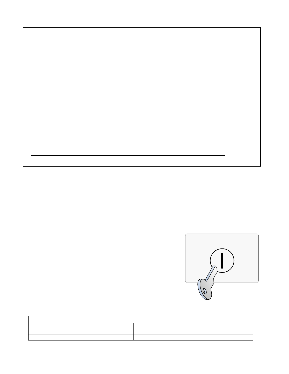
Important! For proper operation, program the SOM-R Output Attributes as follows:
o Gen Alarm Mode = YES
o Silenceable = NO
o Emergency = NO
o Pre Alarm = NO
o Trouble = NO
o Pattern = CONTINUOUS
o Edit Location Text = SOMR
Program the FRCME attributes as follows:
o Set Input Type = GEN PURPOSE N/C EOL
o Set Input Action = SUPERVISORY
Set Input Latch = NO
o
o
Set Input Delay = 0s
o Edit Location Text = SOMR IS DISABLED
Other settings may be assigned as needed.
Failure to follow these programming instructions may result in incorrect
operation of the SOM-R module!
NOTE: The location text will need to be programmed to state “SOMR PREACTION
DISCHARGE” for all initiating devices, which activates the SOM-R module.
Alarm Verification may not be used with the SOM-R.
NOTE: Only one solenoid may be connected to the SOM-R. DO NOT CONNECT
MUTLIPLE SOLENOIDS TO THE SOM-R OUTPUT CIRCUIT!
To Disable the SOM-R:
Move the keyswitch to the “SOM-R Disabled” position.
ENABLE
D
To Enable the SOM-R:
Return the keyswitch to the “SOM-R Enabled” position.
NOTE: DO NOT DISABLE THE SOM-R OR KEYSWITCH
MODULE BY USING THE DISABLEMENTS MENU ON THE
FIRENET CONTROL PANEL!
S
A
B
L
E
Solenoid Compatibility List
Manufacturer Model Number Standby Current (Amps) Alarm Current
ASCO 8210G207 0mA 44mA
Parker/Skinner 73218BN4UNLVNOC111C2 0mA 42mA
I
74
FireNET 4127 I & O Manual v1.90 UL
Page 75

Maintenance:
A maintenance agreement should be arranged through the local
manufacturer’s representative and maintenance should be performed annually by
authorized personnel only. To keep a preaction system in excellent working order,
ongoing maintenance is required per the manufacturer’s recommendations and UL and
NFPA standards. At a minimum the requirements of Chapter 13 of NFPA 25 (2010)
shall be followed.
Test Weekly:
The preaction system should be tested weekly to make sure SOM-R,
FRCME and SOM-R-DS (Bypass Keyswitch) are working properly. The most common
cause of an alarm system not functioning when a fire occurs is inadequate
maintenance.
75
FireNET 4127 I & O Manual v1.90 UL
Page 76

5.15 CZM Conventional Zone Module
The Conventional Zone Module (CZM) connects to the Signal Line Circuit (SLC). The
module allows the analog panel to interface and monitor conventional devices such as
pull stations and two-wire smoke detectors. The CZM is typically used in retrofit
situations where pre-existing conventional zones are removed from a conventional
system and then connected to the analog panel for discrete monitoring of that zone. All
conventional devices connected to a single CZM are reported as a single input. Status
conditions are reported as normal, open or alarm. It supervises the external power
supply as well as the entire zone of devices. Refer to the installation instructions
included with the CZM for more detailed wiring and installation instructions.
FireNET Control
Panel
FireNET
Control Panel
Figure 5.15.1 CZM Conventional Zone Module
76
FireNET 4127 I & O Manual v1.90 UL
Page 77

5.16 DIMM Dual Input Monitor Module
The Hochiki DIMM Dual Input Monitor Modules were designed to work with pull
stations, water flow switches, and other applications requiring the monitoring of dry
contact alarm initiating devices. The DIMM can monitor two independent inputs with
discrete reporting, yet the module only requires a single address on the SLC Loop. A
typical example would be for use with a waterflow and tamper application. One input
would be connected to the waterflow switch for a fire alarm condition. The second input
would be connected to the tamper switch for a supervisory condition. A single DIMM
module would be used instead of two single input modules such as the FRCME. The
DIMM inputs operate in a similar fashion to the FRCME input. Refer to the installation
instructions included with the DIMM for more detailed wiring and installation
instructions.
22k Ω
Ω
22k
FireNET
Control
Panel
77
FireNET 4127 I & O Manual v1.90 UL
Page 78

5.17 SCI Short Circuit Isolator Module
The SCI short circuit isolator module is designed to help maintain partial SLC loop
operation in the event that the SLC loop becomes shorted, positive to negative. In the
event of an SLC loop short circuit the SLC loop is typically inoperative. By installing SCI
modules throughout the SLC loop only a portion of the loop will be inoperative in the
case of an SLC short circuit. When SCI modules are installed adjacent to every device
for true Style 7 (see Section 5.17.1), no devices are lost from a single short on the SLC
loop.
Connect the SCI module to the FireNET 4127 control panel as shown in Figure 5.17.1.
Refer to the installation instructions included with each SCI for more detailed wiring and
installation instructions.
To FN-4127 control panel SLC
loop -or- previous SLC loop
device
+-
(IN) S
(IN) SC
SCI
(OUT) S
(OUT) SC
-
To next SLC loop device or
return back to FireNET 4127
control panel
+
Figure 5.17.1
78
FireNET 4127 I & O Manual v1.90 UL
Page 79

5.17.1 Class A Operation
The SCI should be located within 5 feet of the FN-4127 control panel on both the
outgoing and incoming SLC loop legs. In addition an SCI should be located between
every SLC loop detector and module as shown in figure 5.17.2 and is required for
NFPA 72 Class A Style 7 compliance. For Class A Style 6 compliance the SCI modules
may be located at strategic locations based on the installer’s or system designer’s
discretion.
In the event of a short circuit on the SLC loop the 2 adjacent SCI modules to the short
(closest SCI on the left and the right of the short) will activate and its LED will turn on.
All the devices between the two SCI modules will be isolated and inoperative. All other
devices on that SLC loop will remain operational. The FN-4127 control panel will
indicate a trouble condition. When installing SCI modules for true Style 7 compliance,
the SCI modules must be installed in a “closed nipple” fashion (see Figure 5.17.2). By
using this method, no devices are lost from a single short on the SLC Loop.
Class A Style 7 SLC
loop with SCI Short
Circuit Isolator Modules
SCI
SCI
SCI
1 2 3 4 5 6 7 8 9
-
1 2 3 4 5 6 7 8
OUT
SCI
-
-
9
OUT
-
+
+
+
IN
LOOP 1 LOOP 2 LOOP 3 LOOP 4
SCI
SCI
First and last SCI modules
must be located with 5 feet of
the FN-4127 control pa nel.
10 11 12 13 14 15 16
-
+
+
IN
OUT
SCI
SCI
-
-
+
IN
OUT
SCI
SCI
-
+
+
IN
SCI
SCI
NOTE: For NFPA 72 Style 7
compliance, SCI Modu les and
protected detectors or modules must
be installed in “clo sed-nipple” fashion.
This can be accomplished by eit her
installing two (2) SCI modules and
one (1) protected detector or module
in a single enclosure or raceway, or
by nippling all three devices together
using three separate backboxes
nippled together creating an enclosed
raceway.
SCI
SCI
MAIN CONTROL UNIT
79
FireNET 4127 I & O Manual v1.90 UL
Figure 5.17.2
Page 80

5.17.2 Class B Operation
The SCI modules may be strategically located based on the installer or designer’s
discretion. Typically they are located at the beginning of each branch of the SLC loop
as indicated in figure 5.17.3.
In the event of a short circuit on the SLC loop, the closest SCI to the short circuit will
activate and it’s LED will turn on. All devices following the SCI module will be isolated
and inoperative. All devices preceding the SCI module will remain operational.
80
FireNET 4127 I & O Manual v1.90 UL
Figure 5.17.3
Page 81

5.18 ASB Analog Sounder Base
The Analog Sounder Base (ASB) connects to the SLC Loop and requires 24VDC aux
power to operate. The ASB contains an addressable sounder that is controlled by the
control panel. The ASB derives its address from the Host detector (ALK, ALG, AIE, or
ATG) upon power up. The address is the detector address + 127. See section 5.4 for
additional details. The addressable sounder is independently controlled by the control
panel, and does not have to follow the detector status to activate.
Refer to the installation instructions included with the ASB for more detailed installation
and wiring instructions.
81
FireNET 4127 I & O Manual v1.90 UL
Page 82

5.19 AMS Addressable Manual Pull-Station
The AMS Addressable Manual Pull-Station is an integrated device that includes an
input module and a manual pull-station in a single package.
The AMS is designed to be directly connected to the FN-4127 control panel SLC loop.
The AMS must be programmed with a unique address between 1 – 127. Each AMS will
report individually to the panel based on its unique address. Please refer to Section 5.4
of this manual for instructions on programming an address into the AMS device.
Connect the AMS to the FireNET control panel as shown in Figure 5.19.1. Refer to the
installation instructions included with the AMS device for more detailed installation and
wiring instructions.
OUT TO
NEXT
SC-
MODULE
S+
Hochiki America Corporation
DCP-AMS
Addressable Manual Pull Station
SC-
S+
SC S+
1 2 3 4 5 6 7 8 9 10 11 12 13 14 15 16
-
-
-
-
-
-
OUT
-
+
+
IN
+
+
+
+
+
+
1 2 3 4 5 6 7 8 9
OUT
IN
OUT
LOOP 1 LOOP 2 LOOP 3 LOOP 4
10 11 12 13 14 15 16
IN
OUT
IN
MAIN CONTROL UNIT
Figure 5.19.1 AMS Addressable Manual Pull Station Wiring Detail
82
FireNET 4127 I & O Manual v1.90 UL
Page 83

Section 6 - Network Connections
6.1 Compatible Network Devices
The following Hochiki America Corp. FireNET network devices are listed as compatible
with the FireNET 4127 analog addressable fire alarm system.
Network Interface Card
• FN-4127-NIC
Network Devices
• FN-LCD-N Network LCD Annunciator
This section covers the installation of the devices listed above. For proper operation
each of these devices must be programmed using the Loop Explorer software. Please
refer to Section 9 of this manual for more information on programming the functionality
of network devices.
The FireNET system enables information to be transmitted between control panels
using a secure network connection. Up to sixty-four control panels and network
annunciators (nodes) can be connected together and the system can be configured
such that selected information can be displayed or acted upon at each panel.
83
FireNET 4127 I & O Manual v1.90 UL
Page 84

6.1.1 FN-4127-NIC Network Interface Card
To enable control panels to be connected together
as a network, a network card must be installed in
each panel. This card connects to the FN-4127 on
the rear of the panel door and is held in position by
two M3 screws. The network card is installed in the
exact same fashion for the FN-LCD-N Network LCD
annunciator.
To install a network card, the AC and battery power
must first be switched off and the metal cover over
the front panel PCB removed. The network card can
then be plugged into the two connectors (J1 and J3)
in the bottom right of the main panel PCB and
secured in position with the M3 screws.
OBSERVE STATIC PRECAUTIONS WHEN HANDLING CIRCUIT BOARDS
Each network node must
be allocated a unique
network address. This is
ON
12345678
This switch setting shows address number one.
Switch position up selects the binary digit, so a switch with
1,2 and 3 up would represent address number 7.
(The black part shows the switch actuat or)
done by setting the DIP
switches on the network
card to the required binary
number as shown above.
It is important that each
panel has a different
address for correct
operation so care must be
taken to set and record
the network card address
for each panel. Always set
the address on the DIP
switches with power to the
panel
switched off.
+
C19
R11
+
K6005
R8
R4
C3
OP5
OP6
R7
R10
R12
R2
SW2
C13
C11
C12
+
R26
C7
R25
C20
R28
R27
C16
LED1
C15
LED2
C4
TR4
TR3
R17
TR5
S1
RP1
R24
R13
R14
D1
TR6
D2
J2
U4
R9
U7
+
C17 C18
R16
RL2
RL1
C14
U6
+
C2
R21
R15
R20
R19
U5
This switch setting shows
address number one.
LED1-GREEN = OUTGOING CONNECTION OK LED2-RED = INCOMING CONNECTION OK
Switch position up selects
the binary digit, so a switch with 1,2 and 3 up would represent address number 7.
The network card has a green and a red LED indicator to show the status of the
incoming and outgoing communications. Under normal circumstances, both LEDs will
be lit, indicating that the card is communicating properly. If one or both of the LEDs are
not lit then the connection to neighboring panels is not functioning properly.
Front Panel PCB
M3 Screws
Processor reset switch
+
C1
U1
J1
C10
+
84
FireNET 4127 I & O Manual v1.90 UL
Page 85

6.1.1.1 Cable Length
The FireNET network communications protocol has been designed to be extremely
tolerant to interference and data corruption, however as with any system, limitations
must be set to guarantee correct operation. The specified transmission distance limit for
the communications method used is 4000 ft. (1200m) and because the data is retransmitted at each network card, in theory, there can be 4000 ft. (1200m) between
each card if required. The minimum cable size for the FireNET network is #20 AWG.
The network communications uses RS485 technology.
Using the above cable distances however, does not take into account the failure of a
network card to communicate with the system through total power failure or a card
trouble. In this situation, the network card would disconnect itself from the network and
connect the network cable such that it bypasses the card in question. This means that
the total cable length between the cards either side of the disconnected one could be
8000 ft. (2400m), which is outside of the specification for the communications method
used (RS485). This trouble scenario could clearly be extended to more network cards
and this would add 4000 ft. (1200m) of cable length in each case.
A sensible trouble tolerance limit must therefore be suggested to enable the
performance of the system to be predicted. Because of the nature of the fire protection
system, its design is biased towards inherent reliability and failure of a network card,
although possible, is very unlikely. Fire control panels also have substantial back up
power systems, therefore, the likelihood of a total power failure under operational
conditions, is also extremely rare. A suggested tolerance level of one card failure is
therefore recommended. To guarantee operation of the system with one card failure it
is necessary to arrange the network so that a failure will not introduce more than 4000
ft. (1200m) of cable between the two cards, which would be connected together by the
failure. This means that the total cable length between adjacent nodes should not be
more than 4000 ft. (1200m). It is not important how the 4000 ft. (1200 meters) is made
up i.e. it could be 350 ft. (100m) and 3650 ft. (1100m) or 2000ft. (600m) and 2000ft.
(600m).
Using these general rules and the specified or equivalent cable types will provide a
guaranteed performance of networks with plenty of tolerance.
85
FireNET 4127 I & O Manual v1.90 UL
Page 86

6.1.1.2 Wiring Scheme
4000 ft. Max.
Panel 1
2 LOOP
A B
Panel 2
2 LOOP
Panel 3
4 LOOP
Panel 4
4 LOOP
NetworkNetwork NetworkNetworkNetwork
LCD
Annunciator
When designing or installing a network of FireNET panels and annunciators, always be
aware of the following:
1. The panel network must be wired as a ring (Class A).
2. There should be no more than 4000 ft. (1200m) maximum cable length between
two adjacent segments.
3. A short circuit at
Point A should automatically disconnect the shorted section
and announce a trouble condition at all panels but the entire network will
continue communicating.
4. A short circuit at
Points A and B should automatically disconnect both sections
and announce trouble at all panels. Communication will continue between
panels1 and 4 and between panels 2 and 3.
5. Open circuit troubles should allow the network to continue operating in the same
way as short circuit troubles.
6. Network cabling should be standard RS485 type for up to 64 nodes.
7. The minimum cable size for the FireNET network is #20 AWG.
86
FireNET 4127 I & O Manual v1.90 UL
Page 87

6.1.1.3 Cable Type
The cable type used for the network connection should be suitable for RS-485
applications. Minimum wire size should be 20ga. twisted, shielded, stranded. RS485
communications cable is typically standard Class 2 communications cable. However,
depending on the AHJ, FPL or FPLR cable may be required. Follow local jurisdictional
and AHJ requirements. NFPA 70 national electric code compliance may be required for
network cabling depending on local jurisdiction, AHJ, regulations, and/or codes.
6.1.1.4 Proper Shield Termination of the Network Cable
In many installations, interference from RFI, EMI or other noise sources can create
problems. In order to reduce the effects of such noise, terminate the shield to the earth
ground terminal block in the main control panel. DO NOT ground the shield at both
ends of the cable!
87
FireNET 4127 I & O Manual v1.90 UL
Page 88

4
6.1.1.5 C
A
s
n
d
p
ico
t
e
n
t
t
i
o
e
u
m
N
0
8
p
t
e
o
E
A
7
e
n
r
h
V
.
a
o
F
U
o
e
1
t
y
n
n
.
.
t
ll panel
is not co
The + an
The tem
NOTE: It
to
X1
onnecting
will have
nected th
– from o
erature of
s importan
nnects to t
the IN- of
Terminal Str
the netw
wo cables
n a troubl
e panel m
he cable s
t to ensure
he IN+ ter
he next pa
p
rk cable
connected
will be dis
st connec
hould not
that the c
inal of the
nel and so
to another
layed. Th
to the + a
xceed 131
nnection f
next and t
on.
panel or p
connecti
d – of the
degrees
om the O
e OUT- fr
X2 T
nels. If ei
n is polarit
next panel
(55 C).
T+ from o
m one pa
rminal Strip
her of thes
sensitive
and so on
e panel
el connec
e
s
- + -
OUT I
LOOP
+
- + - +
OUT IN
LOOP 2 LOOP 3
- +
- + - +
- +
OUT
OUT IN
IN
DO NOT PLUG
OR UNPLUG RIBBON CABLES WHILE BOARD IS POW
K60
2 ISSUE 0
NC C NO NC C NO
FIRE 1 TROUBLE
LOOP 4
WARNING!
OBSERVE STATIC HANDLING PROCEDURES
NC C NO NC C NO NC C NO
SUPERVISORY
FIRE 2
RED. STATIC SENSITIVE CIRCUITS
T ALL TIMES
AUXILIARY
+ - + -
NAC 1 NAC 2 NAC 3 NAC 4
PROGRAMMABLE
ADDITIONAL
I/O BOARDS
REMOTE PSU
24
DC
- -
+ +
BATTERY DISCONNECT
+ -
REMOTE
CONTROL
AND AUX.
INPUTS
NETWORK
NETWORK
BATTERY LOW
ROUTING
TROUBLE
ROUTING
OUTPUT
COMMS
AC POWER FAILURE
+ -
+
FIRE
-
+
+
-
1. TBL
2. RES
3. INT
4. CNT
5. SIL
0V
6. PR1
7. PR2
8. PR3
AUX
24V
IN
OUT
CHARGER TROUBLE
GROUND FAULT
l +
l +
l +
l +
Network cable
from “OUT”
terminals of
previous panel/
annunciator
Network cable to
“IN” terminals of
next panel/
annuciator
FireNET
127 I & O
Manual
8
v
.90 UL
Page 89

6.1.2 FN-LCD-N Network Liquid Crystal Display Annunciator
The FN-LCD-N Network Annunciator duplicates the indications of the FN-4127 fire
alarm control panels connected to the same network. The FN-LCD-N connects to the
control panel via the network interface and requires that the main control panel have an
FN-4127-NIC network card fitted.
The FN-LCD-N Network Annunciator is connected to the network and any number of
panels can be connected up to the maximum number of nodes allowed by the network
specification, which is 64 (including control panels).
Specific network attributes and routing information from any or all control panels may
be assigned to the FN-LCD-N. The LCD display and user interface on the FN-LCD-N
operate and indicate in the same manner as the control panel.
The FN-LCD-N is considered a network “node” to the FireNET network just like the
control panels.
For operations and programming refer to Sections 7, 8 and 9 of this manual.
Figure 6.1 FN-LCD-N Network LCD Annunciator
When powering the FN-LCD-N from the FireNET Aux 24VDC power (limited to 500ma), the
following maximum wiring distances apply at the gauges noted:
Wire
18AWG 925ft
16AWG 1500ft
14AWG 2400ft
Distance
89
FireNET 4127 I & O Manual v1.90 UL
Page 90

Figure 6.2 FN-LCD-N Wiring
NOTE: When connecting I/O boards to the FN-LCD-N via the COMMS terminals
shown above, the I/O boards must be powered by a UL864 listed local Auxiliary
24VDC power supply, or the Aux 24VDC output of the FN-LCD-N within the limits
outlined below.
DO NOT
FN-LCD-N unless
24VDC output rating of the FN-LCD-N and
connect the I/O board power input to the Aux 24VDC output terminals of the
the sum current load of the I/O board is within the 500ma max
within the 500ma max 24VDC output rating
of the FN-4127 control panel that provides power to the FN-LCD-N. Failure to make
this consideration may result in overloading the FN-LCD-N and/or the control panel
Aux 24VDC output (500ma max. each).
The current limits during both standby and in alarm shall not exceed the 500 mA rating.
Available Colors: RED and CHARCOAL, FN-LCD-N-R = RED, FN-LCD-N-C =
CHARCOAL
90
FireNET 4127 I & O Manual v1.90 UL
Page 91

Section 7 - Basic Front Panel Operations and Programming
(Access Level 1, 2, and Real-Time Operation)
This section covers the basic user operations of the FN-4127 and is intended to provide
the casual user a basic understanding of how to complete common system operations.
In addition to providing an overview of the front panel controls this section also includes
instructions on how to:
• Perform a Lamp Test
• Silence the Panel Sounder
• View Multiple Fire Alarms on the Panel Display
• View Multiple System Events on the Panel Display
• Use the Menu Navigation Buttons
• Use the Help Function
• Silence an Alarm
• Resound an Alarm
• Reset an Alarm
• Initiate a Fire Drill
• Disable Portions of the System
• View the Status of System Devices
• Set system time
All of these operations are performed from the front panel keypad.
Please refer to the front panel photo in Figure 7.1 below while reading through this
section.
Figure 7.1 Front Panel Control
91
FireNET 4127 I & O Manual v1.90 UL
Page 92

7.1 Operating Modes
This section provides a brief overview of Access Level 1, 2, and 3 operating modes.
Access Level 1 and 2 operating modes are used in the basic system operations
described in this chapter. Access Level 3 is typically used only by installation and
service personnel and is explained in greater detail in Section 8 of this manual.
7.1.1 Access Level 1
When the FN-4127 control panel is in
Power On LED will be lit, and the date and time displayed on the LCD display. Normal
Standby is considered to be in Access Level 1. Some very basic operations can be
done in Access Level 1 by simply pushing the corresponding button(s) on the front
panel controls. For information on which basic user operations can be done from
Access Level 1 see section 7.2.
Note that when using the Denver Door build the control panel buttons are not
accessible until the door is opened.
7.1.2 Access Level 2
Many of the front panel controls and their operations require the user to enter a more
secure operating mode called Access Level 2. This more secure operating mode
prevents unauthorized individuals from operating the FN-4127 fire alarm system. For
information on which basic user operations are done from Access Level 2 see section
7.3.
Normal Standby condition only the green AC
7.1.3 Access Level 3
A higher security mode called Access Level 3 is also available to system
administrators, installers, and service personnel to make critical changes to the system.
For more information on Access Level 3 refer to Section 8 of this manual. None of the
basic operations covered in this section require entry to Access Level 3 operating
mode. Access Level 3 operating mode should be restricted to qualified installation and
service personnel only.
7.2 Access Level 1 Operations
7.2.1 Performing a Lamp Test
Press the “
indicators, LCD display, and validate correct operation. Release the button to conclude
the test.
Lamp Test” button on the front panel to illuminate all front panel LED
92
FireNET 4127 I & O Manual v1.90 UL
Page 93

7.2.2 More Fire Events
The front panel display is capable of displaying the information for up to two different
points that are in alarm condition. If more than two points are in an alarm condition
simultaneously the front panel display above the “
More Fire Events” button will
indicate how many additional alarms are active. For example the display may indicate
1 More Fire”. In this case there is one additional point in fire alarm condition that is not
“
currently shown on the display. By pressing the “
More Fire Events” button, the user
can display these additional alarms.
7.2.3 More Events
Similar to the “More Fire Events” button, the “
More Events” button allows the user to
display more non-fire alarm events if more than 2 events are active on the system at
one time.
7.2.4 Menu Navigation (Up, Down, Left, Right Arrows, Enter / Exit Buttons)
These buttons are used to navigate the FN-4127 menu structure. The arrow buttons
up, right, down, left) also represent the digits 1, 2, 3, and 4 respectively when
(
entering codes for Access Level 2 or Access Level 3 modes.
7.2.5 Help (?)
Help” button offers additional information relating to the current status of the FN-
The “
4127 control panel and provides assistance in basic operation of the system. Press and
hold the “
Note: When using the Denver Door build of the FireNET panel, the front door of the
panel must be opened to perform these commands.
Help” button to display this additional information.
93
FireNET 4127 I & O Manual v1.90 UL
Page 94

7.3 Access Level 2 Operations
The following operations can only be done after the panel is placed into Access Level 2
operating mode. To place the FN-4127 into Access Level 2 follow these instructions:
7.3.1 Entering Access Level 2
1. Press any navigational arrow key to enable the panel.
2. Using the arrow keys enter the 5 digit code. Digit values are 1 - 4 only and
correspond to the value on each arrow key. (Up = 1, Right = 2, Down = 3, Left =
4) The factory default for the Access Level 2 code is 22222.
3. Press the Enter key. The front panel graphic display will confirm you are in
Access Level 2.
4. If there is no activity for 120 seconds on the front panel controls once the system
is in Access Level 2 operating mode, the system will time out and revert back to
Access Level 1 operating mode automatically.
5. You may also use the Enable Access keyswitch on the front door of the panel to
enter Access Level 2. Simply insert the key and turn it to the right. The panel
display will confirm that you are in Access Level 2.
NOTE: The FireNET panel will NOT time out to Level 1 when using the key. Be
sure to return the key to the OFF position and remove it when not in use!
When using the Denver Door build of the FireNET panel, opening the enclosure door
will put the panel into access level 2 automatically.
7.3.2 Silencing an Alarm
To silence an alarm condition place the panel into Access Level 2 operating mode as
described in 7.3.1. Press the “
acknowledges any current alarm conditions and typically silences any audible and
visual notification appliances such as horns and strobes. In some cases the system
may be programmed so that the “Alarm Silence” button silences the audible notification
appliances but allows the visual notification appliances such as strobes to remain
flashing. Your system installer can inform you how your system is set up to operate.
After an alarm has been silenced, the flashing fire LED’s will go steady, and “alarm
silenced” will display in the upper right corner of the LCD display.
Alarm Silence” button. The “Alarm Silence” button
7.3.3 Resounding an Alarm
To resound an alarm condition place the panel into Access Level 2 operating mode as
described in 7.3.1. Press the “
button will reactivate any audible or visual notification appliances that were previously
silenced using the Alarm Silence operation.
Resound Alarm” button. Pressing the “Resound Alarm”
94
FireNET 4127 I & O Manual v1.90 UL
Page 95

7.3.4 Resetting an Alarm
Once a fire or other alarm condition has been verified and cleared it is necessary to
reset the panel. To reset the FN-4127; place the panel into Access Level 2 operating
mode as described in 7.3.1. Press the “Reset” button. All latched outputs such as
relays used for elevator recall will return to their normal state.
Prior to resetting the panel it is necessary to clear the condition that caused the alarm.
For example, if a manual pull station was activated to cause the alarm, that manual pull
station must be physically reset in order to reset the panel. If you attempt to reset a
panel that has an existing alarm condition that has not been cleared, the panel will go
back into alarm immediately after trying to reset.
7.3.5 Initiating a Fire Drill
To initiate a fire drill place the FN-4127 panel into Access Level 2 operating mode as
described in 7.3.1. Press the “Fire Drill” button to engage fire drill mode. The fire drill
activates NAC and SOM indication circuits, but does not activate fire relays, R2M,
programmable relays, etc. A subsequent press of the fire drill button will deactivate fire
drill mode. Any actual fire alarms during a Fire Drill will automatically override fire drill
mode.
7.3.6 Silence the Panel Sounder
Many system conditions such as system troubles will activate the sounder in the FN4127 main control panel. The user can silence the panel sounder by pressing the
Panel Sounder Silence” button on the front panel. This silences only the panel
“
sounder. Other audible outputs such as horns or strobes require a different operation to
silence.
95
FireNET 4127 I & O Manual v1.90 UL
Page 96

7.4 Advanced Access Level 2 Operations
7.4.1 Access Level 2 Main Menu
Once you have entered Access Level 2 operating mode you can view the Access Level
2 Main Menu, which gives the user the ability to perform additional system operational
functions. To view the menu, enter Access Level 2, and then press any one of the
navigational arrow keys.
ACCESS LEVEL 2 MAIN MENU
DISABLEMENTS
VIEW DEVICES
TEST ZONES
SET SYSTEM TIME
SENSOR MAINTENANCE EARLY
WARNING
ACCESS LEVEL 3
Table 7.4 Main menu items at Access Level 2
Once this menu is displayed you can scroll up or down using the navigational arrow
keys to highlight each of the six menu options. A menu option is highlighted when a
triangular arrow symbol appears to its left.
Each menu option may be selected by first highlighting it using the up/down arrow keys,
then pressing the right arrow key to select. The six Access Level 2 Main Menu option
functions are described in the following sections.
7.4.2 Disablements
The Disablements menu allows the user to disable individual points, circuits, zones, or
loops on the FN-4127 fire alarm system. This is typically done while the system is being
serviced or tested or to temporarily remove a faulty system device. CAUTION: Any
portion of the system that is disabled will not report an alarm condition.
All disablements have two options, timed or untimed. For disablements up to 24 hours
in length the timed disablement option should be used. This will prompt the user to
enter a disablement time in 30-minute increments from 30 minutes to 24 hours. Once
the disablement begins the FN-4127 will countdown the selected disablement time.
When the time expires the disablement is cancelled automatically.
Untimed disablements should be used only when it is necessary to disable a portion of
the system for over 24 hours. Untimed disablements remain active until they are
manually reset at the panel through the Access Level 2 Main Menu / Disablements
command.
96
FireNET 4127 I & O Manual v1.90 UL
Page 97

Once you select timed or untimed disablement you can choose to disable loops, zones,
addresses, NAC, or I/O circuits through sub-menus to the Access Level 2 Main Menu /
Disablements option.
As previously discussed highlighting the desired menu option and then pressing the
right navigational arrow selects that option. Pressing the left navigational arrow at any
time backs out of the current menu returning to the previous menu.
Note: The FN-4127 fire alarm system will indicate a disabled condition any time there is
an active disablement on the system, via LCD display text and the “point bypassed”
LED on the front panel. Any item disabled is considered an off-normal condition and will
generate a common trouble condition until the disabled item is returned to normal.
7.4.2.1 Disabling Loops
The Disable Loops sub-menu option to Disablements, allows you to disable an entire
SLC loop with one command. The SLC loop may contain up to 127 analog detectors
and addressable input and/or output modules, as well as up to 127 analog sounder
bases. Disabling an entire SLC loop disables all inputs and outputs on the loop and
should be used only in extreme cases such as a service related problem affecting all
the devices on the SLC loop.
WARNING: Loop disablement does not electrically isolate the panel from the SLC loop
wiring. The SLC loop should be disconnected from the panel before any diagnostic
testing is performed.
Disabling Zones
Each device on the system is assigned to a zone by the system installer. Refer to the
installation records in Section 11 of this manual for a list of all points on the system and
the zones they are assigned to. A zone may consist of one or many points. Disabling a
zone disables all the points assigned to that zone.
Disabling Addresses
Each SLC loop device on the system is assigned a unique address. In some cases an
SLC loop device may have sub addresses as well. Using the Disable Address submenu command the user can individually disable any single address on the system.
97
FireNET 4127 I & O Manual v1.90 UL
Page 98

Disabling NAC Outputs
The disable Audible Device output sub-menu option allows the user to disable all of the
local NAC, SOM, and ASB outputs on the system. This is typically done for periodic
tests so the building occupants are not disturbed while activating each alarm device.
When you choose this option all of the notification appliances connected to the panel
notification appliance circuits and SOM are disabled, as well as any analog sounder
bases.
Disable Panel I/O
The Disable Panel I/O sub-menu option allows a user to disable an individual panel
input or output. This includes individual notification appliance (NAC) circuits, on-board
panel relays, and the on-board digital inputs. This option applies only to on-board
inputs and outputs – SLC loop devices must be disabled by using the Disable
Addresses option.
View / Restore Disablements
The View/Restore Disablements sub-menu option is used to quickly display any system
disablements and optionally reset them to normal. Scroll to the View/Restore
Disablements sub-menu option, press the right navigational arrow to select, and then
follow the prompts on the panel display to view/reset any disablements on the system.
7.4.3 View Devices
The View Devices menu option allows the user to view every SLC loop device. For
each device the panel display will indicate the device type, zone, and location text. In
addition, analog devices such as smoke and heat detectors will also be displayed with
their current analog value. This analog value can be useful in determining if a smoke
detector requires cleaning. Photoelectric detectors also display in terms of obscuration
(%/ft) and the heat detectors in terms of temperature (F°).
For non-analog input devices the current status will be displayed as Off or On. For nonanalog output devices the current status will be displayed as either Off or Activated.
Service personnel who want to verify system devices and troubleshoot potential
problems typically use the View Devices sub-menu option.
7.4.4 Test Zones
The Test Zones sub-menu option is used by service personnel to quickly and easily
perform periodic system tests. Please refer to Section 10 of this manual for a more
detailed explanation. This feature is typically referred to as a “One Man Walk Test.”
98
FireNET 4127 I & O Manual v1.90 UL
Page 99

7.4.5 Set System Time
This sub-menu option is used to adjust the FN-4127 internal clock. It is important to
make sure the clock is accurate so that events logged in the event log are recorded
with the correct time.
To set the system clock, select the Set System Time sub-menu option by highlighting it
with the up/down arrow keys. Select it by pressing the right arrow key. The resulting
menu allows you to individually set the Year, Month, Day, Hour, Minute, and Daylight
Savings. Highlight each option by using the up/down arrow keys. Press the right arrow
key to select it. Use the up/down arrow keys to change the current values. Pressing the
left arrow key in any menu backs you out to the previous menu.
7.4.6 Sensor Maintenance Early Warning
This option is used by service personnel to identify sensors that require cleaning or
replacement.
7.5 Panel Operation
This section summarizes the operations described earlier in this section of the manual
for handling Fire, Trouble, and Supervisory conditions.
7.5.1 Fire Condition
In the event a device on the FN-4127 fire alarm system activates in a fire alarm
condition the following will happen:
• Both FIRE LED indicators on the front panel will turn on and flash.
• Details of the device that caused the fire alarm condition will be given in the LCD
status display on the front panel.
• If there are more than two fire conditions, press the “More Fire Events” button
on the front panel to view the additional fire alarms.
• Audible and visual notif ication appliances (horn and strobes) will activate
throughout the building.
• Output relays and circuits will operate performing fire alarm functions such as
closing doors, recalling elevators, shutting down air handling equipment etc.
• The panel buzzer will be pulsing.
99
FireNET 4127 I & O Manual v1.90 UL
Page 100

The operator actions required following a fire alarm condition are as follows:
• Silence the panel buzzer by pressing the “Panel Sounder Silence” button.
• Silence the notification appliances by entering Access Level 2 and pressing the
Alarm Silence” button. (See section 7.3.1 for instructions on entering Access
“
Level 2). When the Fire condition is silenced, both fire LED indicators change
from flashing to steady and the LCD display will indicate “Alarm Silenced”.
• Resound the audible and visual notification appliances if necessary by entering
Access Level 2 and pressing the “
Resound Alarm” button.
• Once the fire department has cleared the building, physically reset any devices
such as manual pull stations that require a manual reset.
• Reset the FN-4127 fire alarm control panel by entering Access Level 2 and
pressing the “
Reset” button.
7.5.2 Trouble Condition
Trouble conditions occur when problems with the FN-4127 fire alarm system
components and wiring are detected.
When the FN-4127 fire alarm control panel senses a trouble condition, the following will
occur.
• The General Trouble LED will illuminate on the front panel.
• Other trouble LED’s indicating the nature of the trouble may also illuminate.
• The trouble relay contact and voltage output in the control panel will activate
• Details of the trouble condition will be shown on the LCD status display on the
front panel.
• If there are two or more trouble events press the “More Events” button to view
them in the LCD status display on the front panel. (See section 7.3.1 for instructions
on entering Access Level 2).
• The panel buzzer will sound.
The operations required following a trouble condition are as follows:
• Press the “Panel Sounder Silence” button to silence the panel buzzer. (See
section 7.3.1 for instructions on entering Access Level 2).
100
FireNET 4127 I & O Manual v1.90 UL
 Loading...