

Page 1

FIRElink-NANO Air Sampling System
INSTALLATION MANUAL
Page 2

Page 2 of 21 FIRElink-NA NO Air Sampling Detector – Installation and User Manual
This manual details the installation of:
FIRElink-NANO Ai r Sampling Detector
If you have any queri es regarding this product or its functionality please cont ac t:
Hochiki Europe (UK ) Limited
Grosvenor Road
Gillingham Business Park
Gillingham
Kent ME8 0SA
Tel: +44 (0) 1634 260133
Fax: +44 (0) 1634 260132
Web: http:// www.hochik ieurope.com
Email: psupport@hoc hikieurope.com
©2010 Hochiki Europe (UK ) Ltd. All rights reserved. No part of this docum ent m ay be reproduced,
stored in a retri ev al system, or transmitted, i n any form or by any means, without the prior permission i n
writing of Hochiki Europe (UK) Ltd.
Hochiki Europe ( UK ) Limit ed r eserves the right to alter the specifications of its products from time to time
without notice. Although every effort has been made to ensure the accuracy of the information contained
in this document it is not warranted or represented by Hochik i E urope (UK) Limited to be a complete and
up-to-date description.
Document Detail s:
Title: FIRElink-NA NO Air Sampling Detector – Installation and User Manual
Issue 1.0
Issue Date July 2010
Part No. 9-5-0-425
© 2010 Hochiki Europe (UK) Lt d
9-5-0-425/ISS1/JUL10
Page 3

FIRElink-NA NO Air Sampling Detector – Installation and User Manual Page 3 of 21
Table of Contents
1 Introduction.................................................................................................................................. 4
2 Outside the Detector..................................................................................................................... 5
3 Inside the Detector....................................................................................................................... 7
4 Installation: Mechanical................................................................................................................ 8
5 Installation: Printable A4 Drilling Template................................................................................. 9
6 Installation: Electrical................................................................................................................. 10
7 Installation: Pipework................................................................................................................. 12
8 Configuration.............................................................................................................................. 13
8.1 Alarm Factor......................................................................................................................... 13
8.2 ClassiFire® Enabled.............................................................................................................. 13
8.3 Fixed Alarms Enabl ed .......................................................................................................... 14
8.4 Flow Limit Offset................................................................................................................... 14
8.5 Flow Delay........................................................................................................................... 14
8.6 Input Select.......................................................................................................................... 14
8.7 Auto Calibration.................................................................................................................... 14
9 Commissioning........................................................................................................................... 15
10 Maintenance................................................................................................................................ 16
11 Troubleshooting......................................................................................................................... 17
11.1 Nuisance Alarms.................................................................................................................. 17
11.2 Detector Will Not Pass Smoke Test...................................................................................... 17
11.3 Nuisance Flow Faults........................................................................................................... 17
11.4 Long Transport Times: ......................................................................................................... 18
12 Optional Communications Card................................................................................................. 19
13 Technical Data............................................................................................................................ 21
© 2010 Hochiki Europe (UK) Lt d
9-5-0-425/ISS1/JUL10
Page 4
Page 4 of 21 FIRElink-NA NO Air Sampling Detector – Installation and User Manual
1 Introduction
An aspirati ng smoke detector uses a fan to draw samples of air
from a network of pipes with sampling holes positi oned as if they
were point smoke det ec tors.
0832
Hochiki Europe (UK ) Limited
Grosvenor Road
Gillingham Business Park
Gillingham
Kent ME8 0SA, UK
09
0832-CPD-1467
EN54-20: 2006
Aspirati ng smoke detectors
for fire det ection and fire alarm
systems for buildings
CLASS A, B and C
Technical data: see INF48027 held
by the manufacturer
The detector i nc or por ates a patented artificial intelligence system
called ClassiFire
optimum sensitivity for any environment.
This smoke detect or is defined as Cl ass III in EN 60950. It is
designed to operate f r om S afet y Extra Low Voltages and does not
generate any hazardous voltages.
If this detector is to form part of an approved fire detection system,
its power must be supplied from a certified power supply ( typically
EN 54-4).
In order for the installation to conform to EN 54-20, pipes must
conform at least to EN 61386-1 Class 1131.
®
, which allows the unit to adjust itself to the
Please note that pri nted circuit boards are stati c sensit ive and must
not be handled without taking proper stati c precautions.
This symbol indicates that the detector i s a Class 1 laser pr oduc t
as defined in IEC 60825-1. This unit incorporat es a Class 3B
embedded laser which m ust not be removed from the detector, as
retinal damage m ay occur if t he beam enters t he ey e.
This symbol indicates that this product m ust NOT be disposed of
with other waste. It i s the user’s responsibility to dispose of this
product by sending it to an approved reprocessing company, or by
returning it to the manufacturer for reprocessing.
NOTE: Every care has been tak en to ensure that the detector is as easy to install as possible by trained
fire Alarm engineers. In case of difficulty, please contact the Hochiki Product Support Department
(contact details are at the front of this manual) in the first instance to ensure trouble free
installation and operation.
© 2010 Hochiki Europe (UK) Lt d
9-5-0-425/ISS1/JUL10
Page 5
FIRElink-NA NO Air Sampling Detector – Installation and User Manual Page 5 of 21
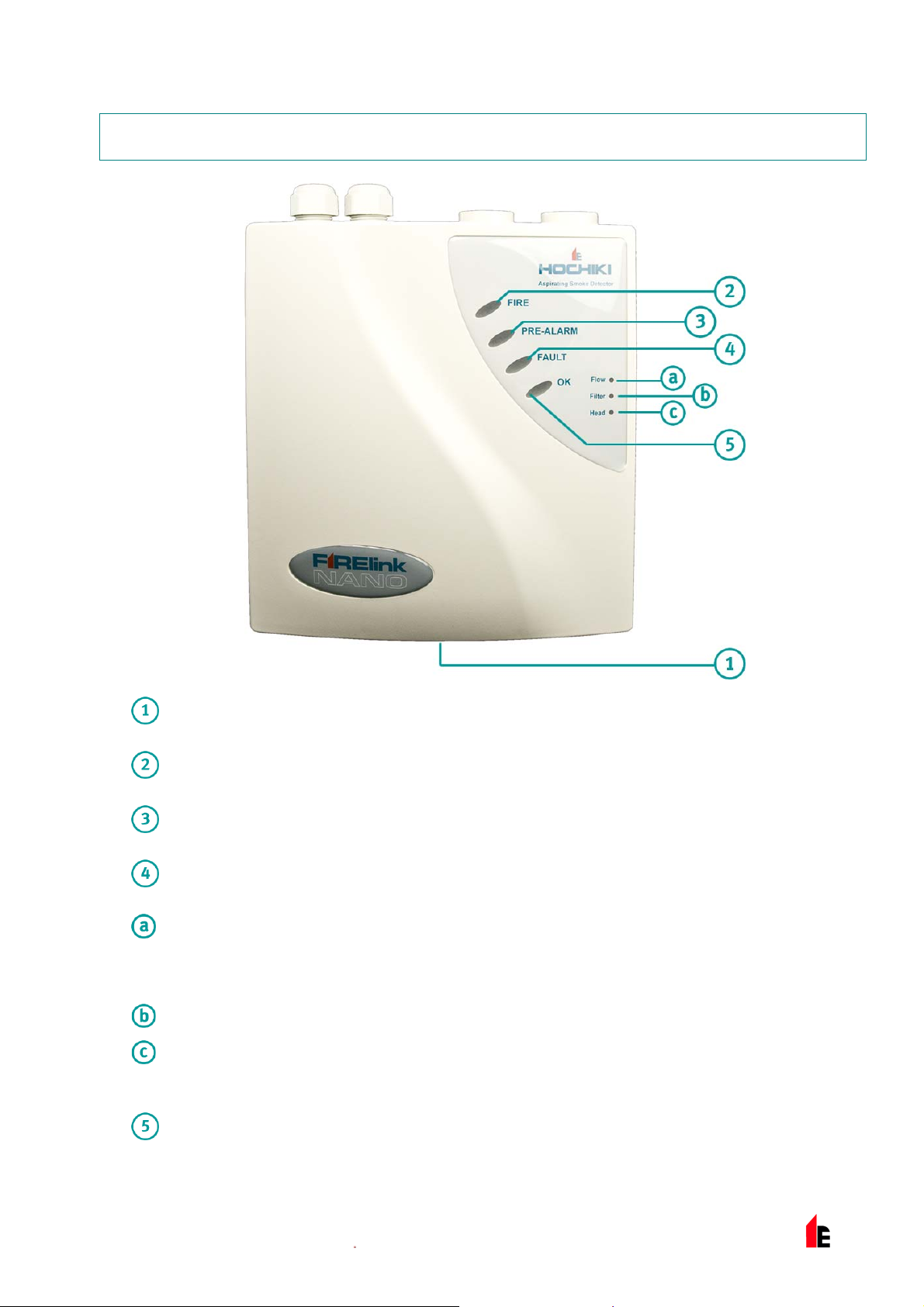
2 Outside the Detector
Front Cover Securing Screw: Leave sufficient cl ear ance bel ow the det ec tor to allow
screwdriver access to this screw.
Fire Alarm: Illuminates to indicate that the sm ok e lev el has passed the detector’s Fire 1
threshold, and t he normally open FIRE relay contacts have closed.
Pre Alarm: Illuminates to indicate that the sm ok e lev el has passed the detector’s Pre Alarm
threshold, and t he normally open PRE ALARM relay contacts have closed.
Fault: Illuminates to indicate a Fault conditi on and that the normally closed FAULT relay
contacts have opened. Three additional LEDs i ndic ate the type of fault:
Flow: Illuminates to indicate an airflow fault . This may be due to blocked or broken pipes,
although it can al so occur if, for example, factory warehouse doors are opened on a windy day,
or if industrial air conditioning tur ns on. Another possible cause is that the aspirating fan
connection c able is damaged or disconnected.
Filter: Illuminates to indi c ate t hat t he detector’s air filter needs to be changed.
Head: Illuminates to indicate a problem with the detector laser chamber, as might be caused if
the laser head connect ing cable is damaged or disconnect ed. It can also be caused by certai n
kinds of internal systems faults, which appear in the detector’s Event Log as “process err or s”.
OK: Illuminates to confirm normal oper ation.
© 2010 Hochiki Europe (UK) Lt d
9-5-0-425/ISS1/JUL10
Page 6

Page 6 of 21 FIRElink-NA NO Air Sampling Detector – Installation and User Manual
NOTE: If the FAULT LED is ill umi nated but none of the additional LEDs are lit , it indicates a problem with
the power supply if its Fault output is connected t o the detect or ’s INP UT terminals and DIL switch
7 is set to OFF (its default position). Alternatively, this can happen if the INPUT terminals are left
open circuit and DIL switch 7 is OFF.
NOTE: During initial setup, the OK LED will flash for 15 mi nutes while the detector learns it s operat ing
environment . Thi s does not i ndic ate a problem with the detector.
© 2010 Hochiki Europe (UK) Lt d
9-5-0-425/ISS1/JUL10
Page 7

FIRElink-NA NO Air Sampling Detector – Installation and User Manual Page 7 of 21
3 Inside the Detector
Aspirating Fan Connector Lead: If this lead is broken or not connected, the fan will not turn
and the detector will indicate a FLOW fault.
Main PCB: No user-serviceable parts. The PCB is fixed in plac e with 5 off M3 x 6 screws. The
detector must not be operated with any of the screws missing, as this may cause air leaks and
unreliable oper ation.
DIL switch: Used to configure user-selectable det ector func tions.
Detector Head Ribbon Connect or: If this lead is broken or not connec ted, the detector will
indicate a “Head” Fault .
Detector Head Co ver Plat e: This protects the laser head. The plat e should not be r em ov ed
from the detector.
Detector Head Assembly: No user-serviceable parts. Do not remove this from the detector
due to the risk of exposure t o the laser.
Replaceable Dust Filt er: This simply slides in and out of its mount ing. The filter and its
replacement hav e IN writt en in red on one side, and OUT on the other to indicate correct
orientati on. The part number for ordering spare dust fi lter s i s 30755.
NOTE: As viewed abov e, I N should be on the left and OUT should be on the right, as indi c ated by the
moulded-i n ar r ows next to the filter slot.
© 2010 Hochiki Europe (UK) Lt d
9-5-0-425/ISS1/JUL10
Page 8

Page 8 of 21 FIRElink-NA NO Air Sampling Detector – Installation and User Manual
4 Installation: Mechanical
Cable Entries
2x 20mm Conduit Holes, for ex am pl e
for 20mm packing glands.
Drilling guides are provided for drilling
two additional 2x 20mm holes in the
top and 1x 20mm hole in the bott om if
needed.
Pipe Entries
¾” ABS Pipe.
Use a ¾” male to 25mm female
adaptor if 25mm pipe is used.
Note: Do not glue pipes into the detector, to
allow for future removal.
Fixing Holes (3 x M5 x 13 slots)
Refer to the pri ntable drilling template on nex t page f or accurate positioning.
NOTE: Ensure the det ector is fixed to a flat surface – otherwise the enclosure will twist and may be
damaged.
© 2010 Hochiki Europe (UK) Lt d
9-5-0-425/ISS1/JUL10
Page 9

FIRElink-NA NO Air Sampling Detector – Installation and User Manual Page 9 of 21
5 Installation: Printable A4 Drilling
Template
Upper clearance
Remember to leave sufficient
clearance above the detector for the
cable glands and pi pe inlet stubs.
3 x wall fixing screw hol es
Use M4.5 pan-head screws suit able for
the wall to which the detector is to be
fixed.
NOTE: The positions of the cross-hairs on this
drawing act as an accurate dr ill
template only if the page is printed at
DIN A4 paper size wit h Print Scaling
disabled. Thi s is norm ally par t of the
main Print menu, and i s usually
enabled by defaul t.
Lower clearance
Remember to leave sufficient space
underneath the detec tor to allow
screwdriver access to the cover fixing
screw and any cable gl and fixed to the
bottom of the det ector .
The screw is M6 x 15 panhead
Pozidrive.
© 2010 Hochiki Europe (UK) Lt d
9-5-0-425/ISS1/JUL10
Page 10

Page 10 of 21 FIRElink-NA NO Air Sampling Detector – Installation and User Manual
6 Installation: Electrical
Power Su pp ly Co nnectio ns
Connect “+24V” to PSU “+” termi nal
Connect “EART H” to PSU mains eart h terminal
Connect “0V” to PSU “-” terminal
Volt-free Relay Con t act s
NB: All relay contact positions are shown with t he detector in
the unpowered state.
The FIRE and PRE ALARM relay cont acts wil l change over
when the unit enters the appr opr iate Alarm state.
The FAULT relay will pull in when the detector is operating
normally. The relay c ontacts will drop out during a Fault
condition.
Remote control inpu t
DIL Switch 7 OFF: Connect to PSU Fault output contacts for
PSU monitoring; N/C OK, N/O PSU Fault*.
DIL Switch 7 ON: Classi F ire® Override will reduce detector
sensitivity by 50% while the input terminal s are short ed
together, e.g. by a key switch.
External communications terminals, optional
communications card fitted (RS-485 serial
communications mode):
Connect Command Module or detector RS-485
(SenseNET™) serial bus to A and B.
Use screened twisted pair c able. Connect screen to either of
the SCREEN terminal(s). Earth the screen at one end ONLY
(if one or more detect or s connected to a Command Module,
earth the cable screen at the Command Module only).
Optional APIC card fitted (addressable communications
mode):
Connect + and - IN and + and -OUT terminals to fire panel
using an APIC compatible with the panel’s communications
protocol.
When one or more detector s are connec ted to a Command
Module, it may be easier t o fit eac h detector with a
communications card and use a single APIC in the Comm and
Module, set t o cover the range of chosen detector addresses.
© 2010 Hochiki Europe (UK) Lt d
9-5-0-425/ISS1/JUL10
Page 11

FIRElink-NA NO Air Sampling Detector – Installation and User Manual Page 11 of 21
In accordance wit h good wir ing practice, keep cabl es and i ndividual bared conduct or s as short as
possible whil e allowing stress-reliev ing cable forming. Power cables should be current-rated at 1A or
greater. RS- 485 c able shoul d be screened twisted pair, e.g. Belden 9841 24AWG.
*NOTE The factory default setting of DIL switch 7 is OFF, so that the detector can monitor a power
supply. If power supply m onitoring and ClassiFire Override are not required, l eave DIL switch 7
set to OFF and fit a wire link acr oss the two term inals to prevent a Faul t condition on power up.
© 2010 Hochiki Europe (UK) Lt d
9-5-0-425/ISS1/JUL10
Page 12

Page 12 of 21 FIRElink-NA NO Air Sampling Detector – Installation and User Manual
7 Installation: Pipework
Sampling pipe
¾” pipe or 25mm pipe with a ¾” sleev e
adapter.
The maximum sampling pipe length is
50m.
Fit an end cap with an appropriately-sized
hole to optimize airflow through the pipe.
This end cap hole is al so a sampling hole.
Use the PipeCAD
software to pl an pipe installations. For E N
54-20 compliance, indicated hole
sensitivities must be better than, or equal
to: 0.80% obs/m (Cl ass A), 1.66% obs/m
(Class B) or 5.85% obs/m (Class C)
Do not glue the pipe into t he sampling
inlet.
®
pipe layout modelling
Exhaust pipe
¾” pipe or 25mm pipe with a ¾” sleev e
adapter.
If the protected area is at a lower
atmospheric pressure than the location in
which the detect or is i nstalled (e.g. a
closed air-c onditioned room), fit a retur n
pipe run from the detector exhaust to the
protected area, in order to equalise the
pressure. Thi s will im pr ov e detector
performance.
Even if the protected area and detector are
at the same atmospheri c pr essure, it is
good practic e to fit a pipe stub with a bend
to the exhaust, to prev ent debris falling into
the detector .
Do not glue the pipe into t he ex haust
outlet.
© 2010 Hochiki Europe (UK) Lt d
9-5-0-425/ISS1/JUL10
Page 13

FIRElink-NA NO Air Sampling Detector – Installation and User Manual Page 13 of 21
8 Configuration
Configurati on is carried out via the DIL switch mount ed on the Main PCB.
Switch 1 Switch 2 Switch 3 Switch 4 Switch 5 Switch 6 Switch 7 Switch
Set Detector
Sensitivity
Alarm Factor 6
Alarm Factor 7 On Off
Alarm Factor 8 Off On
Alarm Factor 9 On On
ClassiFire® Enabled
Fixed Alarms
Enabled
Off Off
On
Off
8
Flow Limit Offset
±40 Off Off
±20 On Off
±5
±3 On On
Flow Delay
240sec
30sec On
Input Select
PSU Fault
ClassiFire Override On
Auto Calibration
Enable
Disable On
NOTE: Text in red denotes the EN 54-20 test configur ation (factory def ault) setting.
Off On
Off
Off
Off
8.1 Alarm Factor
The detector calculates sensitivit y relative to the ambient environmental conditi ons. Higher Alarm Factors
provide reduced sensit ivity (the Alarm t hr eshol d is maintained further away from the ambient level). Refer
to the Remote Software m anual for further details.
NOTE: Changing the Alarm Factor starts a new FastLearn cycle: during the initial 15 minute learning
period, the detec tor is incapable of reporting an alarm. The unit will take 24 hours to achieve
optimum performance, based on the ambient conditions.
8.2 ClassiFire® Enabled
Allows the artificial intelligenc e system to continuously adjust Alarm thresholds in order to avoid unwanted
Alarms from environm ental changes (recomm ended) .
NOTE: Enabli ng this feature means that nuisance alarms due to fluctuations i n the ambient environment
become less likely.
© 2010 Hochiki Europe (UK) Lt d
9-5-0-425/ISS1/JUL10
Page 14

Page 14 of 21 FIRElink-NA NO Air Sampling Detector – Installation and User Manual
8.3 Fixed Alarms Enabled
Switches the artificial intelligence system off, locking sensitivity to that set at initial setup. This deactivates the dust f ilter monitoring system (not recommended).
NOTE: Enabli ng this feature means that nuisance alarms due to fluctuations i n am bient pollution levels
become more likely.
8.4 Flow Limit Offset
Sets the sensitiv ity of the airflow monitoring system. A small offset makes the system v ery sensit ive to air
flow changes. EN 54-20 system s must react to a ±20% change in airflow, which equates to a change in
flow sensor output of +
of airfl ow). Areas with fl uctuating air pressures may require a less sensitive setting.
NOTE: Changing the fl ow limi t offset starts a new flow calibration set up.
5 (this refers to a percentage of flow sensor full output and is not a direct measure
8.5 Flow Delay
Sets the period duri ng whic h abnor mally high or low air flow conditions must continue before the unit
indicates a “Flow” fault.
8.6 Input Select
When this switch is set to t he factory default OFF position, the detector input terminals may be connected
to a power supply fault out put relay so as to generate a detector “Fault” condition if the power supply
Fault relay contacts open. If power supply monit or ing is not required, eit her a wire link can be placed
across the input termi nals, or this switch can be set to ON to remove the fault.
®
Setting the switc h to ON enables the ClassiFire
50% as long as there is a short ci rcuit ac ross the input terminal s, e.g. contr olled by a key switch. This can
be used to prevent unwanted Alarms during planned intervals of smoke release, e. g., inc ense burning
during a church service.
NOTE: If a wire link is fitted across the INPUT terminals, it is important that this switch be set to OFF, or
the detector sensitivity will be dramatically reduced by the ClassiFire® Override function being
permanently enabled.
Override feature. This reduces detector sensit ivity by
8.7 Auto Calibration
Automatically starts a new FastLearn cycle when the detector is powered up. This may be disabled if the
previous setti ngs need to be r etained.
NOTE: if this functi on is enabl ed, the unit will also recalibrat e the flow sensors after power up.
© 2010 Hochiki Europe (UK) Lt d
9-5-0-425/ISS1/JUL10
Page 15

FIRElink-NA NO Air Sampling Detector – Installation and User Manual Page 15 of 21
9 Commissioning
Local standards and speci fication requi r em ents must be adhered to. A typical commissioning procedure
might entail the following steps:
Check install ation against
design document ation
T
Set detector configuration DIL
switches as required
T
Disconnect detector from fire
panel if required
T
Power up detector and wait for
15 minute FastLearn cy cl e to
finish (steady “O K ” LED when
complete)
T
Check/test connec tions to main
Fire Detecti on and Al arm
System
T
Smoke test: check maximum
transport time is less than 120s,
verify sampling hole sensitiviti es
as required. Verify that smoke is
not prevented f r om reaching
sampling holes, e.g. by strong
air currents such as might be
caused by air-conditioning units
T
© 2010 Hochiki Europe (UK) Lt d
Reconnect detector to fire panel
required
if
T
Complete test records; record
settings and results for
referenc e by maint enanc e
engineers
9-5-0-425/ISS1/JUL10
Page 16

Page 16 of 21 FIRElink-NA NO Air Sampling Detector – Installation and User Manual
10 Maintenance
Local standards and speci fication requi r em ents must be adhered to. A typical maintenanc e pr ocedure
could entail the following steps:
Check detector , wiring and
pipework for damage
T
Check original design is still
valid, e. g. changes due to
building upgrades
T
Check detector for
contamination and clean if
necessary
T
Check maintenance logs for
issues and rectify as appropriate
T
Isolate detec tor from the fire
panel if required
T
Smoke test to check detector
operation and Fi r e r elay
connection
T
Check transport times against
original r ec or ds: si gnificant
increases or decrease s i n
transport times may imply
damaged pipes or sam pling
holes that need clearing
T
Simulate a Fault to check the
Fault relay and connec tion
T
Complete and file maintenance
records
T
Reconnect detector to fire panel
if required
NOTE: It is prudent t o disconnect or isolate the detector from the fire panel during m aintenance to prevent
unintentional alarm activations.
NOTE: The detect or should be powered down dur ing internal cl eaning (use an air duster can or dry air
gun).
© 2010 Hochiki Europe (UK) Lt d
9-5-0-425/ISS1/JUL10
Page 17

FIRElink-NA NO Air Sampling Detector – Installation and User Manual Page 17 of 21
11 Troubleshooting
.1 Nuisance Alarms
This normall y i ndic ates that the detector is set at an Alarm F actor inappr opr iate for the installed
environment .
Increase the Alarm F actor t o reduce sensiti vity.
The sensor chamber m ay be cont ami nated.
Return the detecto r for f actor y cleaning and recalibration.
.2 Detector Will Not Pass Smoke Test
Detector may be in a FastLearn cycle.
Check if green OK LED is on and flashing.
The detector FastLear n c y cl e m ay have been carried out during, or immediately after, a smok e test.
Reinitiate FastLearn with the detector in a cl ean environment.
The Alarm Factor i s too high.
Change the Alarm Factor to a lower, more sensitive, setting.
.3 Nuisance Flow Faults
Flow monitoring is too sensitive for the environment.
Increase the flow li mit offset.
Airflow may be subjec t t o tempor ary changes (spikes).
Increase flow fault delay.
© 2010 Hochiki Europe (UK) Lt d
9-5-0-425/ISS1/JUL10
Page 18

Page 18 of 21 FIRElink-NA NO Air Sampling Detector – Installation and User Manual
1.4 Long Transport Times:
The sampling pipe m ay be too long, may have too many sampling holes/capi llaries, or may have
incorrectly sized holes.
Check design with pip e modelli ng software.
Sampling pipes, sampling holes and/or the ex haust pipe may be partially blocked by dust or debris.
Clean pipewo rk with dry comp ressed ai r and/or clean the sampling holes.
Fan may be defective.
Send detector for repair.
Fan lead may be disconnected
Reconnect lead.
© 2010 Hochiki Europe (UK) Lt d
9-5-0-425/ISS1/JUL10
Page 19

FIRElink-NA NO Air Sampling Detector – Installation and User Manual Page 19 of 21
12 Optional Communications Card
A communications card m ay be fit ted inside the detector.
Board Locating Post
Detector Address DIL Switch
The detector address i s set using a reverse binary code, i.e. switch 1 is the least signif icant bit
and switch 7 is the most signif ic ant bit. Switch 8 is not used.
Set the address fr om 001 to 127 in or der to identify the detector. Addresses in a detector
network do not have to be consecut ive but must be different.
2 off M3 x 6 Fixing Screws
Provided wit h boar d.
RS-232 Serial Port
Use 9-pin D-type null modem cable to connect to PC.
© 2010 Hochiki Europe (UK) Lt d
9-5-0-425/ISS1/JUL10
Page 20

Page 20 of 21 FIRElink-NA NO Air Sampling Detector – Installation and User Manual
Direct connect ion of a PC to the Communications Card is via a 9 pin RS-232 interface on the
Communicati ons Card, usi ng a null modem cable configurati on, as shown in the diagram below:
A connected PC may access the detec tor event memory to review previous or current events, such as
detector Alarms or Faults. The detector int er nal Char t Recorder may also be accessed to all ow analy si s
of detector behaviour (see separate Remot e S oft ware Manual for further information). The PC cannot be
used to configure the detector except to enter time and date settings for the detect or Event Log and Char t
Recorder to be viewed in t he Rem ote Software. The detector does not i nc or por ate a real time clock, so
the time and date need to be re- entered if the detector is powered down for any r eason.
Installation of the Communications Card also provides the detector with RS-485 network communic ation
via the A, B and SCREEN terminal s on the detector main board. This can be used f or simple remote
display i ndic ation or integration into a larger site wide management and displ ay system, separate from the
local Fire Detection and Alarm System.
© 2010 Hochiki Europe (UK) Lt d
9-5-0-425/ISS1/JUL10
Page 21

FIRElink-NA NO Air Sampling Detector – Installation and User Manual Page 21 of 21
13 Technical Data
SELV Rating EN 60950 Class III
Supply Voltage. 21.6v – 26.4v DC
Current Consumpt ion 350mA
Electri c al Safety Complies with E N 610190-1
Size (mm) 190w x 230h x 110d
Weight 1.2kg
Operating Temperature Range.
Operating Humidity Range
IP Rating IP50
Sensitivity Range 0.4% to 25% obscuration/metre
Detection Principle Laser light forward scattering mass detection
0°C to 38°C (UL 268)
-10°C to 60°C (EN 54-20)
0 to 90% relative humidity, non-condensing
EN61010-1 Pollution Degree 1
EN61010-1 Installation Category II
Maximum Number of Sampling
Holes
Maximum Sampling Pipe
Length
Sampling Pipe I nlets 2 off 3/4” pipe inlets (sampling pipe and exhaust)
Alarm / Fault Relays Pre Alarm / Fire / Fault
Relay Contact Rati ng
(Changeover)
Programmi ng Internal DIL switc hes
PC Interrogation. Via optional Communications Card
APIC Compatible Yes
NOTE: Some devic es such as sounders and beacons have high inrush curr ents on activation, which can
damage relay contacts. It is good practice to consider fitting a suitabl e current limiting resistor in
series with the load to avoid this potential problem.
Cla ss A: 2
Cla ss B: 4
Class C: 10
50m
1A at 24V DC (resistiv e load)
© 2010 Hochiki Europe (UK) Lt d
9-5-0-425/ISS1/JUL10
 Loading...