

Page 1

FIRElink-400 Air Sampling System
INSTALLATION MANUAL
Page 2

Page 2 of 58 FIRElink-400 Air Sampling System – Installation Manual
This manual details the installation of:
FIRElink-400 Air Sampling System
If you have any queries regarding this product or its functionality please contact:
Hochiki Europe (UK) Limited
Grosvenor Road
Gillingham Business Park
Gillingham
Kent ME8 0SA
Tel: +44 (0) 1634 260133
Fax: +44 (0) 1634 260132
Web: http://www.hochikieurope.com
Email: psupport@hochikieurope.com
©2010 Hochiki Europe (UK) Ltd. All rights reserved. No part of this document may be reproduced,
stored in a retrieval system, or transmitted, in any form or by any means, without the prior permission in
writing of Hochiki Europe (UK) Ltd.
Hochiki Europe (UK) Limited reserves the right to alter the specifications of its products from time to time
without notice. Although every effort has been made to ensure the accuracy of the information contained
in this document it is not warranted or represented by Hochiki Europe (UK) Limited to be a complete and
up-to-date description.
Document Details:
Title: FIRElink-400 Air Sampling System - Installation Manual
Issue 4.0
Issue Date October 2010
Part No. 9-5-0-346
© 2010 Hochiki Europe (UK) Ltd
9-5-0-346/ISS4/OCT10
Page 3

FIRElink-400 Air Sampling System – Installation Manual Page 3 of 58
Table of Contents
1 Introduction.................................................................................................................................... 5
2 Types of Detectors......................................................................................................................... 6
2.1 FIRElink-400 Standard Detector ............................................................................................. 6
2.2 FIRElink-400CM Command Module Detector & FIRElink-CM Stand Alone Command Module 7
2.3 FIRElink-400 Standard Detector - Interior View....................................................................... 8
2.4 FIRElink-400CM Command Module Detector – Interior View .................................................. 9
2.5 FIRElink-CM Stand Alone Command Module – Interior View ................................................ 10
3 Controls & Indicators................................................................................................................... 11
3.1 FIRElink-400 ........................................................................................................................ 11
3.2 FIRElink-400CM & FIRElink-CM ........................................................................................... 11
3.3 Types of Display................................................................................................................... 13
4 Programming the unit.................................................................................................................. 14
4.1 Engineering Access Code .................................................................................................... 14
4.2 Main Menu ........................................................................................................................... 14
4.3 Navigating Through the Menus............................................................................................. 15
4.4 FIRElink-400 Functions ........................................................................................................ 16
4.4.1 Time and Date (Numeric – Address 000-127) ................................................................... 16
4.4.2 Alarm Levels (Numeric – Address 001-127)...................................................................... 17
4.4.3 Alarm Delays (Numeric - Address 001-127) ...................................................................... 17
4.4.4 ClassiFire® Override (Numeric - Address 001-127) .......................................................... 17
4.4.5 ClassiFire® Alarm Factor (Numeric - Address 001-127).................................................... 17
4.4.6 Hour Start of Day and Night Operation (Numeric - Address 001-127)................................ 18
4.4.7 LDD™ Enable (Yes/No - Address 001-127) ...................................................................... 18
4.4.8 Start / Stop FastLearn (Yes/No - Address 001-127) .......................................................... 18
4.4.9 Auto FastLearn Enable / Disable (Yes/No - Address 001-127) .......................................... 18
4.4.10 Time Delay Override (Yes/No - Address 001-127) ............................................................ 19
4.4.11 Cascading alarms (Yes/No - Address 001-127) ................................................................ 19
4.4.12 Latching Alarms (Yes/No - Address 000-127) ................................................................... 19
4.4.13 Latching faults (Yes/No - Address 000-127)...................................................................... 19
4.4.14 Remote Day/Night (Yes/No - Address 001-127)................................................................ 19
4.4.15 Remote Reset Enable (Yes/No - Address 000-127) .......................................................... 19
4.4.16 Remote Isolate Enable (Yes/No - Address 000-127) ......................................................... 19
4.4.17 Programmed Isolate (Yes/No - Address 000-127) ............................................................. 20
4.4.18 Detector Address / Number of Detectors (Display - Address 000-127) .............................. 20
4.4.19 Device Text (Alpha - Address 000-127) ............................................................................ 20
4.4.20 Reference Device (Numeric - Address 001-127) ............................................................... 20
4.4.21 Reference Enable (Yes/No - Address 001-127) ................................................................ 20
4.4.22 Reference Level (Numeric - Address 001-127) ................................................................. 20
4.4.23 Back-off (Numeric - Address 001-127).............................................................................. 20
4.4.24 Reset, Test & Isolate Button Enable/Disable (Yes/No - Detectors 000-127) ...................... 21
4.4.25 Power Save Enable (Yes/No - Addresses 001-127) .......................................................... 21
4.4.26 Battery Check Enable (Yes/No - Address 000-127) .......................................................... 21
4.4.27 Mains Check Enable (Yes/No - Address 000-127) ............................................................ 21
4.4.28 Aspirator Speed (Numeric - Address 001-127).................................................................. 21
4.4.29 Flow Setup (Yes/No - Address 001-127) ........................................................................... 21
4.4.30 Airflow Monitoring (Display / Numeric - Address 001-127)................................................. 22
4.4.31 Chart Log Recording Rate (Numeric - Address 000-127) .................................................. 22
4.4.32 User Defined Access Code (Numeric - Address 000-127) ................................................. 23
4.4.33 BMS Protocol (Numeric - CM only)................................................................................... 23
4.4.34 Factory Default (Yes/No - Address 000 - 127)................................................................... 23
4.4.35 Scan Devices (Yes/No - CM only)..................................................................................... 23
4.4.36 Looped Bus (Yes/No - CM only) ....................................................................................... 24
4.4.37 Poll Timeout (Numeric - CM only)..................................................................................... 24
4.4.38 Call Centre (Numeric - CM only)....................................................................................... 24
4.4.39 Password (Alpha - CM only)............................................................................................. 24
4.4.40 Pager (Numeric - CM only)............................................................................................... 25
4.4.41 Page on Fault (Yes/No - CM only) .................................................................................... 25
4.4.42 Page on Alarm (Yes/No - CM only)................................................................................... 25
4.4.43 View Event Log (Display - Address 000-127) .................................................................... 25
4.4.44 Diagnostics (Test - Address 001-127)............................................................................... 25
© 2010 Hochiki Europe (UK) Ltd
9-5-0-346/ISS4/OCT10
Page 4

Page 4 of 58 FIRElink-400 Air Sampling System – Installation Manual
Detector Read (Display - Address 001-127) ......................................................................25
4.4.45
4.4.46 Loop Errors (Display) ........................................................................................................25
4.4.47 Dust Separator Condition (Display - Address 001-127)......................................................26
4.4.48 Relay Tests (Test - Address 000-127) ...............................................................................26
4.4.49 Watchdog Trip Count (Display) .........................................................................................26
4.5 Menu Map.............................................................................................................................27
5 Sampling Pipe Design ..................................................................................................................28
5.1 Pipework...............................................................................................................................28
6 Installation.....................................................................................................................................30
6.1 General.................................................................................................................................30
6.2 Mechanical Installation ..........................................................................................................30
6.2.1 Removal and replacement of the detector front cover ........................................................31
6.3 Electrical Installation .............................................................................................................33
6.3.1 Detector Terminal Block Connections................................................................................33
6.3.2 Command Module Terminal Block Connections ................................................................34
6.4 Connecting Power Cables .....................................................................................................34
6.5 Power Supply Connections ...................................................................................................36
6.5.1 Detector Power Supply Connections .................................................................................36
6.5.2 Command Module Power Supply Connections ..................................................................36
6.5.3 Command Module Internal Power Supply..........................................................................36
6.5.4 Backup Batteries...............................................................................................................38
6.6 Demonstration Mode.............................................................................................................39
6.7 EN54-20 Compliance............................................................................................................40
7 External Communications............................................................................................................41
7.1 BMS Protocols on the FIRElink-400 Command Module .........................................................41
7.1.1 Text Output Support (Protocol 1).......................................................................................41
7.1.2 BACnet Support (Protocol 2).............................................................................................41
7.1.3 Paging from the Command Module ...................................................................................42
7.1.4 Configuring the software ...................................................................................................42
8 Event Log ......................................................................................................................................44
9 Interfacing.....................................................................................................................................45
9.1 Setting the Detector Address.................................................................................................45
9.2 Connecting a Detector Network to a Command Module.........................................................46
9.2.1 Fault Tolerant Detector Loop Configuration .......................................................................46
9.2.2 Non Fault Tolerant Serial Configuration.............................................................................47
9.3 Connecting a Command Module to an Addressable Fire Panel..............................................47
9.4 Connecting a Single FIRElink-400 to an Addressable Fire Panel ...........................................49
9.5 Connecting to a PC ...............................................................................................................49
10 Commissioning .........................................................................................................................51
10.1 Commissioning Checklist ......................................................................................................51
11 Maintenance ..............................................................................................................................52
12 Troubleshooting........................................................................................................................53
12.1 Pressing RESET or ISOL. Button Has No Effect....................................................................53
12.2 Nuisance Alarms Occur Too Often ........................................................................................53
12.3 Elevated Smoke Levels Do Not Generate Alarms..................................................................53
12.4 Low Mean Output..................................................................................................................53
12.5 Detector Sensitivity Varies Over Time ...................................................................................54
12.6 Flow Fault Errors...................................................................................................................54
12.6.1 "Low flow" Error Messages................................................................................................54
12.6.2 "High flow" Error Messages...............................................................................................54
12.7 Cannot Refit the Front Cover.................................................................................................54
12.8 No Display ............................................................................................................................55
13 Error Messages .........................................................................................................................56
14 Do's and Don’ts.........................................................................................................................57
15 FIRElink-400 Specification ........................................................................................................58
© 2010 Hochiki Europe (UK) Ltd
9-5-0-346/ISS4/OCT10
Page 5
FIRElink-400 Air Sampling System – Installation Manual Page 5 of 58
1 Introduction
FIRElink-400 is a highly sophisticated ‘next generation‘ of High Sensitivity Aspirating Smoke Detection
products that has been designed to ensure that installation and commissioning is as simple as possible,
while optimising performance.
FIRElink-400 incorporates a patented ‘artificial
intelligence‘ known as ClassiFire ®, which allows the
detector to configure itself to optimum sensitivity,
alarm thresholds and minimum nuisance alarms for
0832
Hochiki Europe (UK) Limited
Grosvenor Road
Gillingham Business Park
Gillingham
Kent ME8 0SA, UK
09
0832-CPD-1191
0832-CPD-1192
EN54-20: 2006
any environment. ClassiFire intelligence also monitors
the detector chamber and dust separator for
contamination, continually adjusting the appropriate
operating parameters to counteract the negative
effects of such contamination.
FIRElink-400 is unique in being able to provide a
consistent level of protection in a very wide range of
environments by continuously making minor
adjustments to sensitivity. FIRElink-400 has proven its
worth many times by detecting ‘difficult-to-detect‘ slow
growth electrical overload incipient fires in ‘difficult‘
environments.
This handbook gives information likely to be needed
for most installations, but for more detailed information
on subjects such as Fresh Air Referencing, please
refer to the complete Technical Manual or System
Design Guide.
Aspirating smoke detectors
for fire detection and fire alarm
systems for buildings
CLASS A, B and C
Technical data: see INF48027 held
by the manufacturer
NOTE: If this equipment is part of a fire detection system, it should be supplied from an approved power
supply conforming to EN54-4.
This symbol appears on the main board of the unit and indicates that the board
contains static sensitive components. Suitable anti-static precautions must be
taken when handling the board.
This label is located on the laser chamber and signifies that the unit is a Class 1
LASER CLASS 1
PRODUCT
Laser product as specified in IEC 60825-1. The unit incorporates a Class 3B
embedded laser that must not be removed from the detector as retinal damage
may result if the laser beam enters the eye.
This equipment is Class 111 as defined in EN60950
(in other words, this equipment is designed to operate
from Safety Extra Low Voltages and does not
generate any hazardous voltages). As this equipment
is part of a fire detection system, it should be supplied
from an approved power supply conforming to EN54-
4.
© 2010 Hochiki Europe (UK) Ltd
9-5-0-346/ISS4/OCT10
Page 6
Page 6 of 58 FIRElink-400 Air Sampling System – Installation Manual
This symbol appears on the main board of the unit and indicates that the board
contains static sensitive components. Suitable anti-static precautions must be
taken when handling the board.
Hochiki Europe has taken every care to ensure that FIRElink-400 is as simple to install as possible but in
case of difficulty, please contact our Product Support Department to ensure trouble free installation and
operation (see page 2).
Hochiki Europe takes no responsibility for damage or injury occasioned as a result of failing to install or
operate the equipment in accordance with these instructions.
Throughout this manual where an entry is shown as
on the detector’s LCD screen (if fitted) when that option is selected.
Entries shown as <EXAMPLE> represent function buttons on the front of the detector.
Example it is meant to represent the text displayed
2 Types of Detectors
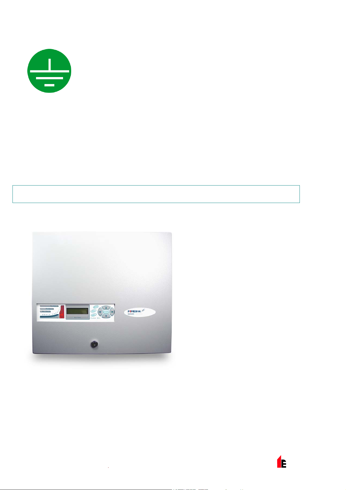
2.1 FIRElink-400 Standard Detector
The Standard Detector may be operated
as a stand-alone unit, or may be part of a
network of detectors centrally monitored
by a Command Module (see "FIRElink400CM Command Module Detector &
FIRElink-CM Stand Alone Command
Module on page 7).
It may be programmed via the front panel
as in the version shown left. Alternatively,
and for detectors ordered without front
panel display, the detector may be
programmed remotely via the detector’s
RS485 terminals using a Command
Module, or via the detector’s RS232 port
using a PC running the remote control
software. A copy of this software is
packed with each detector supplied.
© 2010 Hochiki Europe (UK) Ltd
9-5-0-346/ISS4/OCT10
Page 7
FIRElink-400 Air Sampling System – Installation Manual Page 7 of 58
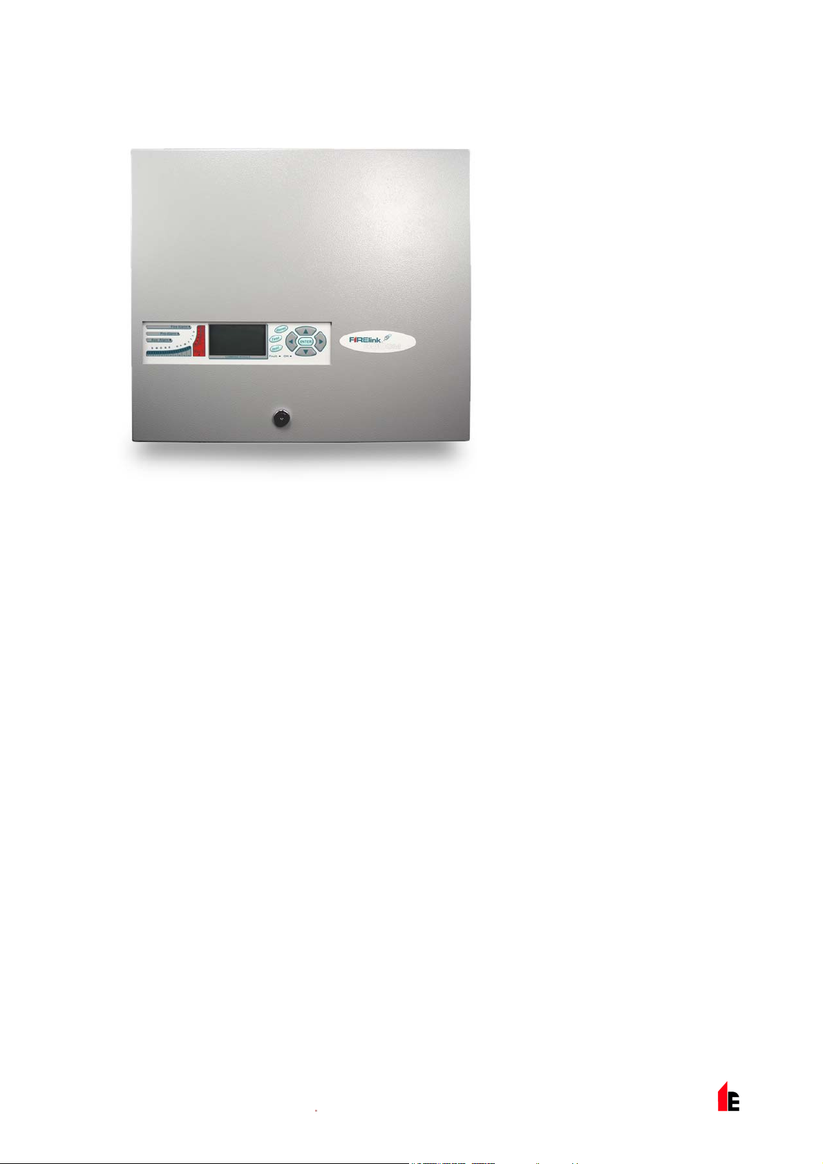
2.2 FIRElink-400CM Command Module Detector &
FIRElink-CM Stand Alone Command Module
When multiple detectors are networked
together, a Command Module may be used
to tie all the detectors together and to
provide a central point for programming,
running diagnostics and PC and fire panel
connection.
The Command Module can be mounted
either inside a detector as shown or as a
stand-alone unit in its own housing without
an aspirator or smoke detection circuitry.
If detectors attached to the Command
Module are mounted in different fire zones
then the Command Module must be
mounted in its own housing with separate
power supply to comply with BS5839 and
EN54.
When a Command Module is mounted inside a detector, the Standard Detector display is replaced with a
dedicated Command Module display. The programming buttons and display on the front of the detector
belong to the Command Module.
Programming from the Command Module is very similar to programming a detector, the main difference
being that the Command Module has extra functions to control all the FIRElink-400 detectors connected
to the detector loop.
© 2010 Hochiki Europe (UK) Ltd
9-5-0-346/ISS4/OCT10
Page 8
Page 8 of 58 FIRElink-400 Air Sampling System – Installation Manual
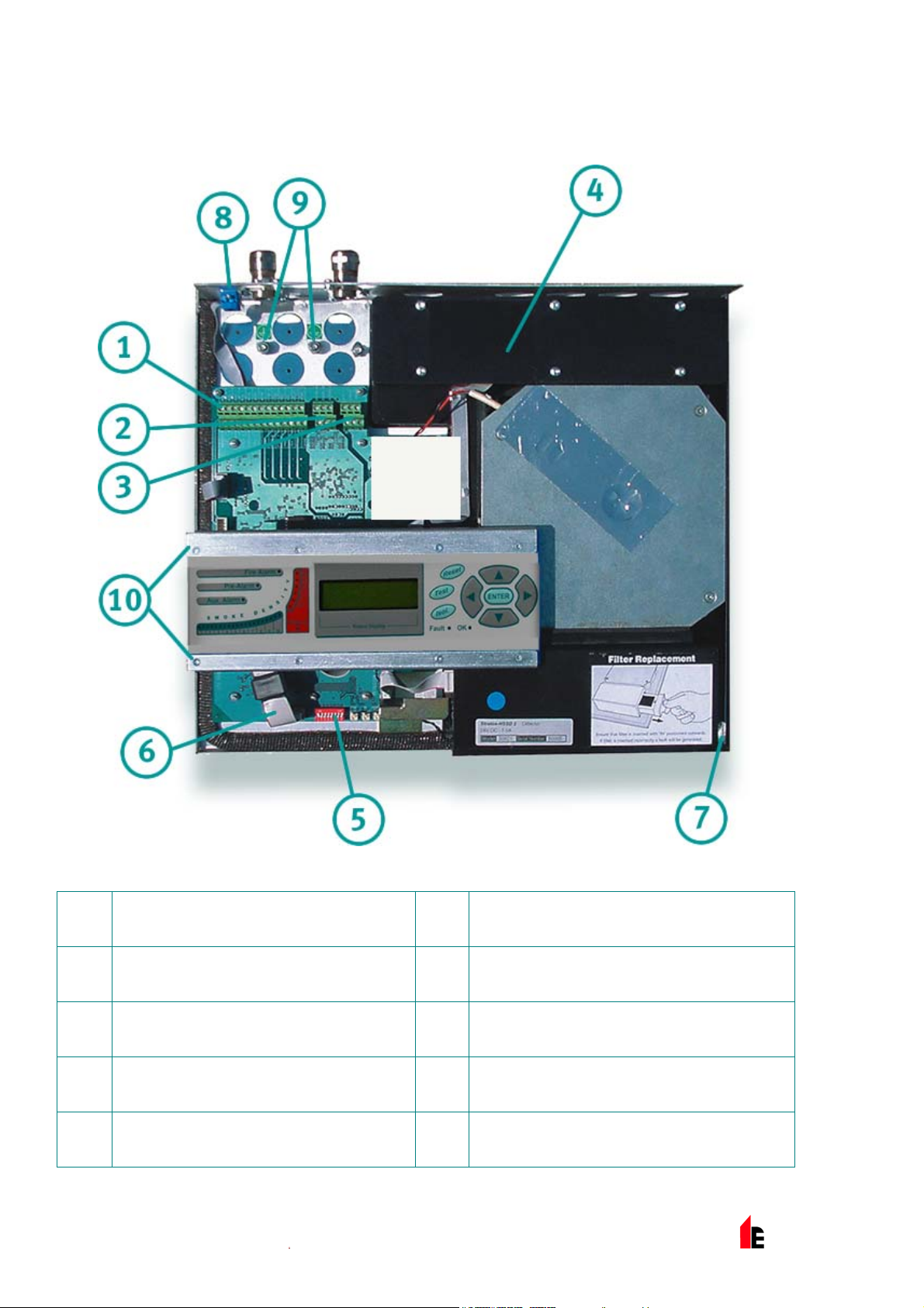
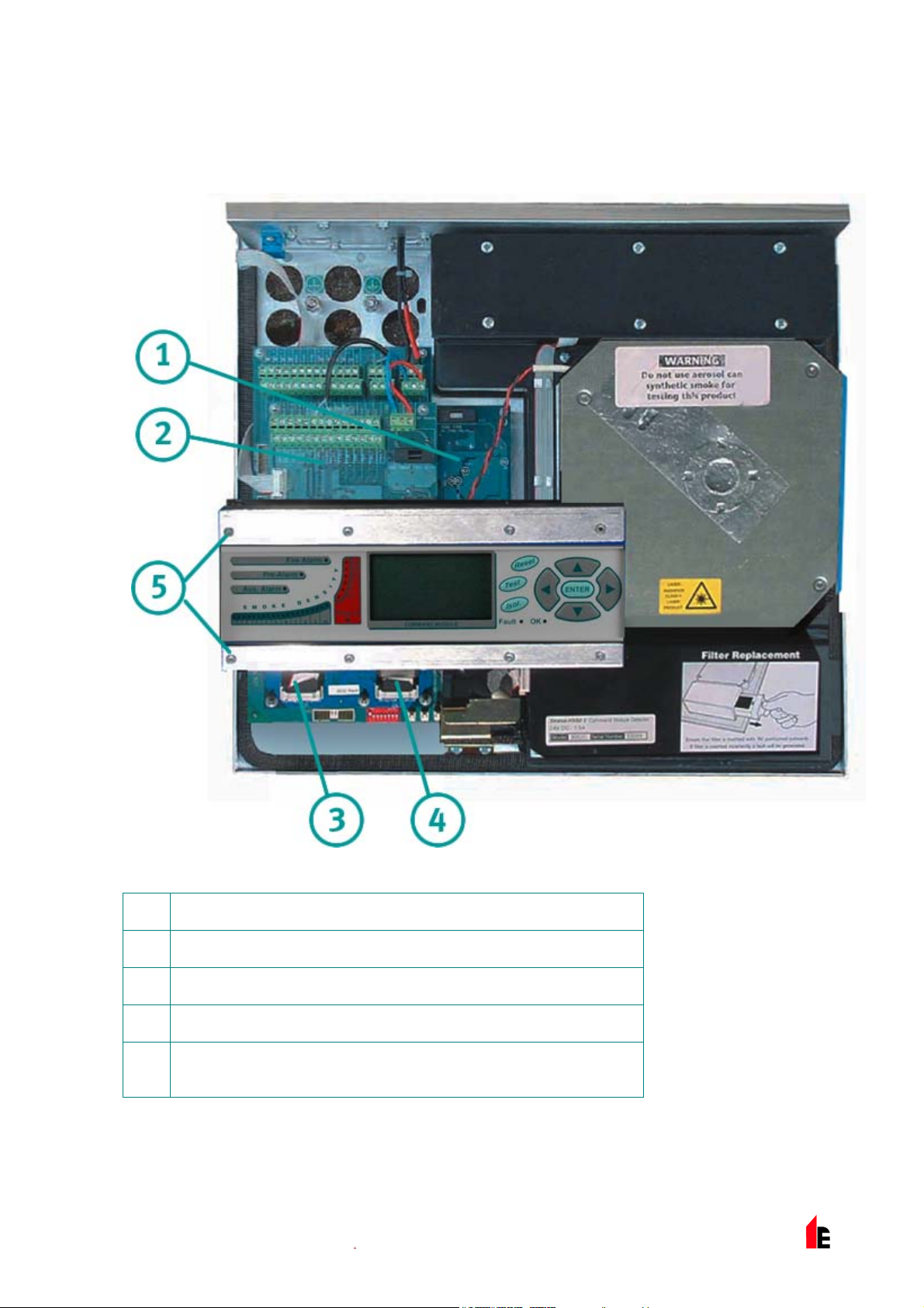
2.3 FIRElink-400 Standard Detector - Interior View
Terminal block connections (see section
1
185554080.01.1.1 on page 33)
RS485 terminal connections (see section
2
185554080.01.1.1 on page 33)
24VDC power supply connections (see
3
section 185554080.01.1.1 on page 36)
1A 5 x 20mm T-type protection fuse
4
Detector address DIP switch (see section
5
9.1 on page 45)
© 2010 Hochiki Europe (UK) Ltd
Front panel display connector
6
Filter removal tab (see section 11 on page
7
52)
RS232 serial port (see section 9.5 on page
8
49)
Safety earth studs (see section 6.5 on page
9
36)
10
9-5-0-346/ISS4/OCT10
Display fixing screws x 8 (see section
185554080.01.1.1 on page 31)
Page 9
FIRElink-400 Air Sampling System – Installation Manual Page 9 of 58
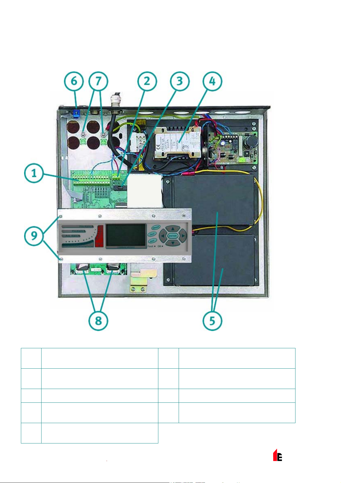
2.4 FIRElink-400CM Command Module Detector – Interior
View
Detector CPU board (see section 2.3 on page 8)
1
Command Module CPU board (see section 2.4 on page 9)
2
Command Module display connection
3
Detector display connection
4
Display fixing screws x 6 (see section 185619544.01.1.1 on page
5
31)
© 2010 Hochiki Europe (UK) Ltd
9-5-0-346/ISS4/OCT10
Page 10
Page 10 of 58 FIRElink-400 Air Sampling System – Installation Manual
2.5 FIRElink-CM Stand Alone Command Module – Interior
View
Terminal block connections (see section
1
185619544.01.1.1 on page 33)
24VDC power supply connections (see
2
section 185619544.01.1.1 on page 36)
500mA 5 x 20mm T-type protection fuse
3
Internal power supply (see section
4
185619544.01.1.1 on page 36)
Stand-by batteries (see section
5
185619544.01.1.1 on page 38)
© 2010 Hochiki Europe (UK) Ltd
RS232 serial port
6
Safety earth studs (see section 6.5 on
7
page 36)
Front panel display connectors
8
Display fixing screws x 6 (see section
9
185619544.01.1.1 on page 31)
9-5-0-346/ISS4/OCT10
Page 11
FIRElink-400 Air Sampling System – Installation Manual Page 11 of 58
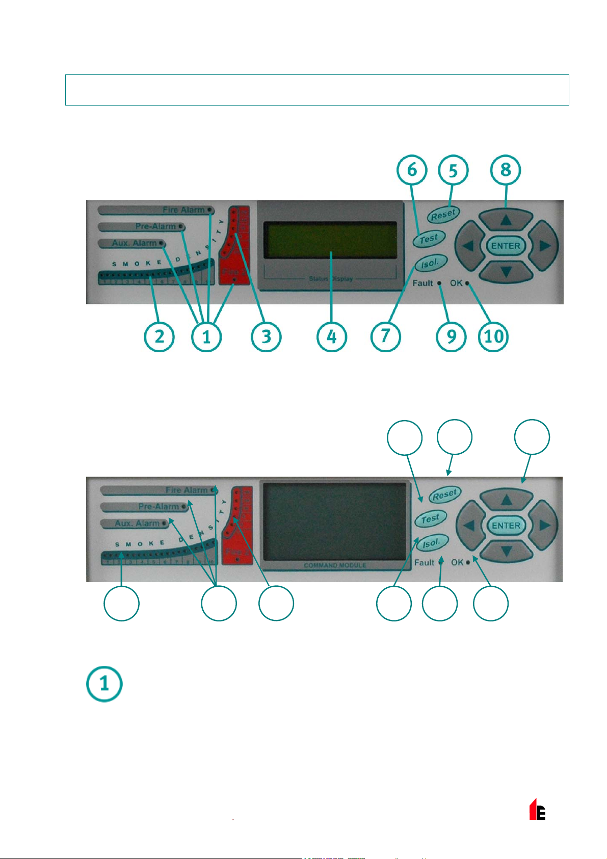
3 Controls & Indicators
3.1 FIRElink-400
3.2 FIRElink-400CM & FIRElink-CM
2
1
3
5 6
4
9 107
Aux, Pre-Alarm, Fire 1 and Fire 2 indicators illuminate when the appropriate alarm
level has been reached and the appropriate time delays have expired.
© 2010 Hochiki Europe (UK) Ltd
On a stand-alone Command Module, the indicators signify an alarm condition from any
detector on the communications loop.
9-5-0-346/ISS4/OCT10
Page 12
Page 12 of 58 FIRElink-400 Air Sampling System – Installation Manual
Smoke density indicators. This display is in two sections. The first part, labelled 1 to
10, is the relatively scaled ClassiFire ® bar graph and changes in steps of half a
segment. The second part displays absolutely scaled smoke levels above 1%
obscuration per metre (% obs/m) to a maximum of 25% obs/m. The Fire 2 activation
level is programmed normally somewhere in this range. The bar graph display will
show a continually cycling pattern when the unit is in FastLearn mode.
On the Command Module display, this will occur when any unit on the RS485
communications loop is in FastLearn. Otherwise, the bar graph display on the
Command Module will mimic the bar graph display on the highest-reading detector on
the loop.
Status display (if fitted). This display shows all events as they happen in real time and
is also used to configure the unit. See section 4 “Programming the unit” on page 14 for
more information.
RESET. When enabled, pressing <RESET> will clear any latched alarms or faults and
set the status display back to its normal operation display. To comply with national
standards, detectors are supplied with the RESET function disabled as default.
TEST. When enabled, pressing <TEST> will start a lamp test and then the detector will
show its nominal operating sensitivity as calculated by the ClassiFire Artificial
NOTE: These three buttons can be individually enabled or disabled. The factory default state of the
detector is for only the <TEST> button to be enabled and for <RESET> and <ISOL> to be
disabled
Intelligence System.
ISOL. Pressing <ISOL> will toggle the unit‘s isolation state. When isolated, the unit
cannot generate any alarms and will signal a fault condition and the text display will
show Panel Isolate. To comply with national standards, detectors are supplied with the
ISOL button disabled as default.
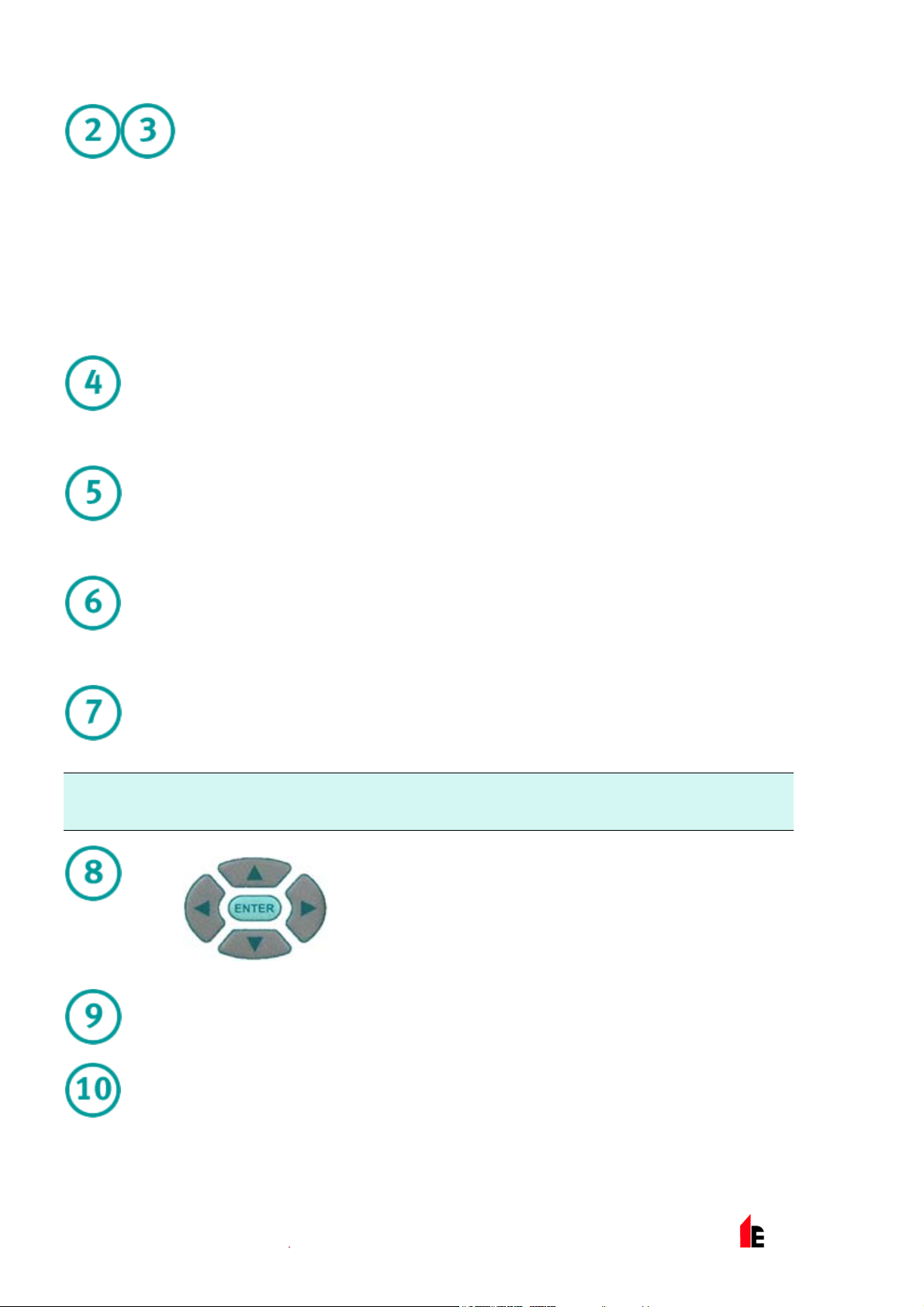
These buttons, also referred to in the text as menu buttons or by
name, for example <ENTER>, are used when programming the
unit, which is pass code protected. See section 4 “Programming
the unit” on page 14 for more information. Pressing when not in
programming mode (the access code has NOT been entered)
will scroll through the detector’s event log. See section 8 “Event
Log” on page 44 for more information.
FAULT. Illuminates when the unit has a fault and a fault signal is being sent to the fire
alarm panel. On the Command Module, this also indicates a fault in a detector on the
communications loop, or in the loop itself.
OK. Illuminates to show normal operation when there are no faults. On the Command
Module this means that the Command Module and all detectors on the loop are
© 2010 Hochiki Europe (UK) Ltd
operating normally.
9-5-0-346/ISS4/OCT10
Page 13
FIRElink-400 Air Sampling System – Installation Manual Page 13 of 58
3.3 Types of Display
The Standard Detector display is a two-line LCD, which allows basic programming of the detector:
Latching faults
Enter Yes/No:Yes
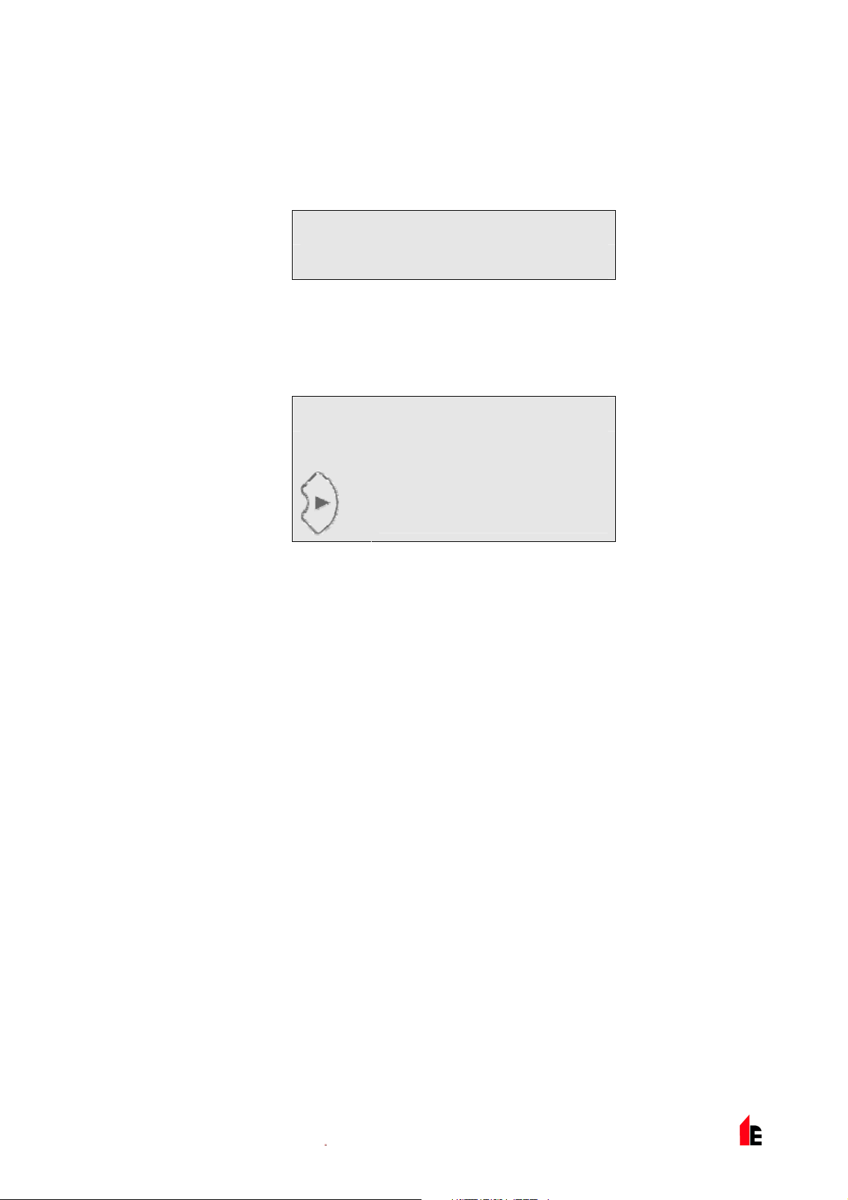
The Command Module display contains more information than that for the Standard Detector and
prompts the user with the action expected by the use of graphic symbols:
Latching faults
Enter Yes/No:Yes
Press
to change
© 2010 Hochiki Europe (UK) Ltd
9-5-0-346/ISS4/OCT10
Page 14
Page 14 of 58 FIRElink-400 Air Sampling System – Installation Manual
4 Programming the unit
The FIRElink-400 programmer means that programming and configuration of the unit can be performed
without opening the detector case.
To enter programming mode, press any of the program menu keys
, ,or .
4.1 Engineering Access Code
The Engineering Access code is required to allow the detector parameters to be programmed. The
access code is only valid whilst the user is in programming mode. It will need to be entered again if
programming mode is exited, if the detector is powered down or if <RESET> is pressed.
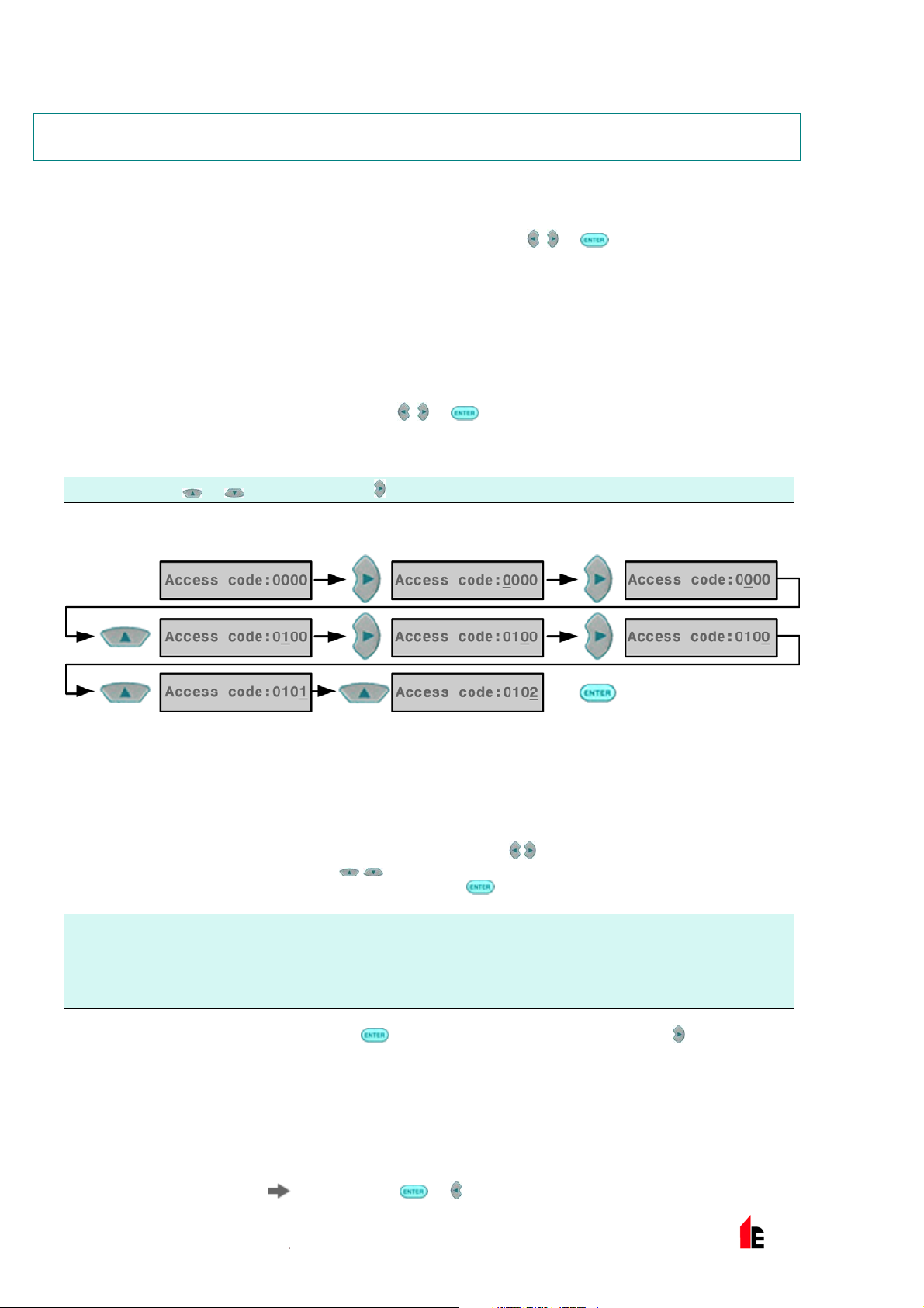
To enter programming mode, press a menu key
Acces s code:0000 asking for the engineering access code. The factory default access code is
0102. To enter the default access code, follow the sequence shown:
NOTE: Pressing or has no effect until is pressed to place the cursor under the first digit.
, ,or . The unit responds by displaying the prompt
This correctly sets the access code. If an incorrect access code is entered or <RESET> is pressed, the
display will show
access code.
All of the programmable functions work in a similar manner. The
through the user-settable digits and the
selected digit (for example 1 - 99, Yes / No etc). Pressing
NOTE: That it is not possible to save an illegal value, for example for the Fire 1 level the maximum valid
input is 10 and it would be possible to enter 99, but the programmer will display Bad value to
inform you that the entry is invalid and prompt for the value to be re-entered. All programmable
parameters have the valid input values range in brackets below the parameter legend on the
display.
Having edited the value as required, press to select the amended setting. Pressing when the
cursor is on the right most digit has the same effect. If no programming activity is detected for 5 minutes,
the detector will display the legend
Bad access code. Pressing a menu key will prompt the user again for the correct
keys move the cursor position
keys step through the available values for the currently
enters the displayed figure.
Access timeout and exit the programming mode.
4.2 Main Menu
When the correct access code is entered, the display will show the main menu. The current selection is
always shown with an arrow (
© 2010 Hochiki Europe (UK) Ltd
) after it. Press or to activate the selection.
9-5-0-346/ISS4/OCT10
Page 15
FIRElink-400 Air Sampling System – Installation Manual Page 15 of 58
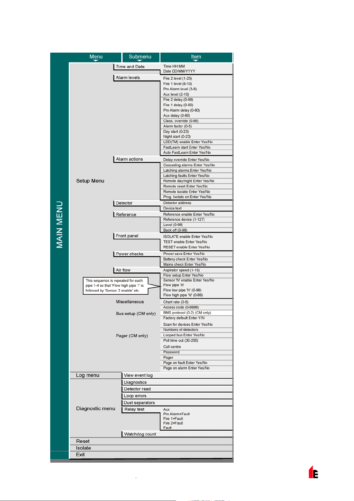
The choices available in the main menu are, in order:
Setup menu contains all the user-programmable functions
Log menu Allows the user to view historical information such as the event
log (time and date of various events such as alarm or fault
conditions)
Diagnostic menu Contains a number of detector self-tests
Reset Clears any latched fault readings or exits from a menu item to its
parent menu. This has the same effect as pressing the
<RESET> button.
Isolate Isolates the detector. This has the same effect as isolating with
the <ISOL> button,
Exit Exits programming mode
NOTE: The main menu ‘wraps around‘ so that pressing when in Setup menu brings up Exit etc.
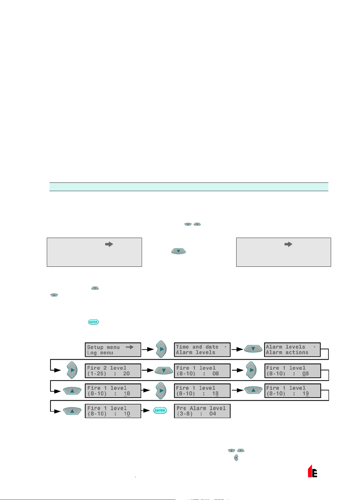
4.3 Navigating Through the Menus
To navigate through the main menu options, press to navigate through the available choices. The
display shows two adjacent items, for example:
Setup menu Log menu
Pressing would then show
Log menu
In other words,
.
The currently selected item is the upper item of the two and is identified by a trailing arrow as shown (for
a menu) or a trailing dot (for a menu item or single choice such as Exit ). When you have the menu you
require, press
set the main fire alarm level:
selects items lower in the list by effectively scrolling the screen UP, and vice versa for
. This then gives you a choice of the items within the selected menu. For example, to
Diagnostic menu
Having entered the
Alarm levels submenu. Either this can be edited as above, or can be used to move to the
next choice. Once the last entry in the sub-menu is reached pressing
© 2010 Hochiki Europe (UK) Ltd
Fire 1 level, the selected item indicator steps along to the item below it in the
will move you back up to the
9-5-0-346/ISS4/OCT10
Page 16

Page 16 of 58 FIRElink-400 Air Sampling System – Installation Manual
Setup menu. Pressing <RESET> at any time exits programming mode, assuming the <RESET> button is
enabled.
section 4.5 on page 27shows the full menu map for the FIRElink-400 ®, showing the choices available
within each menu and submenu.
map as appropriate, and
Items within sub-menus are sequentially accessed with the
are edited with
followed by .
step up/down the choices in the currently selected menu or submenu.
move the menu pointer progressively towards the left or right of the
button followed by the button. Values
4.4 FIRElink-400 Functions
A list of all programmable functions follows with an explanation of their usage and the menu and
submenu in which they can be found. The location of each sub-menu and function within the main menu
is shown in the menu map (section 4.5 on page 27). The menu map also shows the valid input range for
programming parameters.
Each function listed below gives the following information:
Function name and description
Type of function. There are five types of function: Yes/No, Numeric, Alpha (alphanumeric), Display
and Test. In the case of the Display and Test functions, the user cannot amend the parameters
shown.
The menu and submenu within which the function can be found.
Applicability. The legend "CM only" means that the function applies only to the Command Module
and is not present in the Standard Detector’s list.
The legend "Address 000-127" means that the function may apply to the Command Module and
the Standard Detector (allowable addresses from 000 to 127).
test
are examples of these.
All other functions are present in both the Standard Detector and Command Module function lists
and are used to program the detectors. They can either be remotely set on the Command Module,
or locally on the detector front panel. These are annotated "Address 001-127" since they do not
apply to the Command Module itself.
Where a programmable function on the Command Module applies to a Standard Detector, the Command
module will scan the loop and, if more than one detector is present, will prompt the user for the address of
the detector to be programmed. If the function applies to the Command Module, the address "000"
should be entered. For other detectors on the loop (including the detector element of a Command
Module detector), the value is the same as the address set on the detector’s internal DIP switch. If a user
enters an address which does not appear on the loop, the error message
This message will also appear if the Command Module address "000" is entered into a function which
only applies to detectors, in other words anything except "CM only" and "Address 000-127" functions.
Time and date and Relay
Bad detector will appear.
1.1.1 Time and Date (Numeric – Address 000-127)
Setup Menu > Time and date
It is important that the time and date be set up correctly on the controller’s internal calendar/clock
because it uses this information to store events in the event log. See section 8 “Event Log” on page 44
for more information. Unless specially ordered, units are supplied with the correct setting for UK time.
This is backed up with a rechargeable battery. Later adjustments to the clock setting should not exceed ±
70 minutes unless a FastLearn is initiated.
© 2010 Hochiki Europe (UK) Ltd
9-5-0-346/ISS4/OCT10
Page 17

FIRElink-400 Air Sampling System – Installation Manual Page 17 of 58
1.1.1 Alarm Levels (Numeric – Address 001-127)
Setup Menu > Alarm levels
The value set in the Pre Alarm level , Fire 1 level and Aux level functions in the Alarm levels submenu is
the relatively scaled bargraph level at which the appropriate alarm is initiated on the detector. The Fire 2
level function assigns an absolutely scaled alarm level in % obs/m to the Fire 2 alarm. The Aux level is
set by factory default at level 10 which means that this alarm will occur after the Fire 1 alarm.
1.1.1 Alarm Delays (Numeric - Address 001-127)
Setup Menu > Alarm levels
The alarm delay is the number of seconds that an alarm level has to be continuously sensed before the
alarm is initiated. Each alarm level has a programmable delay of between 0 and 90 seconds.
1.1.1 ClassiFire® Override (Numeric - Address 001-127)
Setup Menu > Alarm levels
When this function is set to a value other than zero, the shorting together of one of the "Input 3" contacts
on the detector main circuit board by means of volt free contacts will desensitise the detector by moving
the alarm levels out by the specified percentage.
1.1.1 ClassiFire® Alarm Factor (Numeric - Address 001-127)
Setup Menu > Alarm levels
The detector sensitivity is set with this entry, which will also affect the probability of nuisance alarms. 0 =
high sensitivity/higher probability, 8 = low sensitivity/lower probability.
NOTE: The highest sensitivity setting is suitable for clean, environmentally controlled environments, for
example, semiconductor manufacturing clean rooms where airborne pollutants are kept to an
absolute minimum and the least contamination is cause for alarm.
Use of this setting in a busy machine shop would lead to relatively frequent nuisance alarms due
to the normal variation of atmospheric contamination and a lower sensitivity setting is
recommended. It is therefore important that the alarm factor chosen is suitable for the area to be
protected. When the appropriate alarm factor for the protected area has been set, nuisance
alarms will be reduced to an absolute minimum.
The following table gives suggested settings of ClassiFire alarm setting for different locations:
Alarm
Factor
0 Extremely High Once per year Semiconductor manufacturing clean room
1 Once per 5 years Computer Room
Sensitivity
Probability of Nuisance
Alarm
Suggested Protected Area
2 Once per 10 years Non-Smoking Office
3 Once per 50 years Clean Factory
4 Medium Once per 1000 years Warehouse
5 Medium Once per 5,000 years Warehouse with diesel trucks operating
6 Medium Once per 10,000 years Warehouse with diesel trucks operating
© 2010 Hochiki Europe (UK) Ltd
9-5-0-346/ISS4/OCT10
Page 18
Page 18 of 58 FIRElink-400 Air Sampling System – Installation Manual
7 Low Once per 20,000 years Warehouse with diesel trucks operating
8 Low Once per 100,000 years Warehouse with diesel trucks operating
1.1.1 Hour Start of Day and Night Operation (Numeric - Address 001-127)
Setup Menu > Alarm levels
These values are the times to the nearest hour at which the day/night switching is desired to take place
on the detector. Entries are made in 24-hour format, for example, 19:00 for 7pm. If no day/night
switching is required, then both entries should be set to 00:00. Day and night switching is intended so
that the detector may automatically select a different sensitivity when the protected area is unoccupied
and fewer contaminants are being produced. ClassiFire automatically detects the change in smoke level
after the protected area is left, and if the time at which this happens is within ±70 minutes of the
programmed switchover time it selects the night-time histogram.
NOTE: If the environment actually becomes more contaminated during the night period for any reason
then ClassiFire will adapt to that too, reducing the night-time sensitivity. The system will
automatically compensate for 1 hour seasonal time-changes.
1.1.1 LDD™ Enable (Yes/No - Address 001-127)
Setup Menu > Alarm levels
When this function is set to Yes, Laser Dust Discrimination (LDD) increases the response time of the
detector slightly, whilst greatly reducing the likelihood of nuisance alarms due to dust ingress. LDD may
be disabled in very clean rooms for a slightly faster response to smoke by setting this function to
Disabling LDD is not recommended for areas other than manufacturing clean rooms, due to the increased
probability of nuisance alarms in most other operating environments.
No.
1.1.1 Start / Stop FastLearn (Yes/No - Address 001-127)
Setup Menu > Alarm levels
If the detector is in FastLearn mode, setting this function to No will stop the FastLearn process. Using the
function in this way is neither recommended nor supported by Hochiki Europe (UK) Limited. Setting this
function to
show a rolling segment display on the front panel for the fifteen minutes that it takes to complete.
The text display will initially display the legend
until the FastLearn is complete.
IMPORTANT
Yes will start a FastLearn at any time. The bar graph display on the front of the detector will
FastLearn 15 and will then count down each minute
It will take a further 24 hours after the FastLearn for full sensitivity to be reached, unless
Demonstration Mode has been initiated. It is essential for proper functioning that the
detector not be left in Demonstration mode, and that it be allowed to complete the 24hour learning period. To cancel demo mode, set this function to Yes or power down and
restart the detector to initiate FastLearn mode.
NOTE
1.1.1 Auto FastLearn Enable / Disable (Yes/No - Address 001-127)
Setup Menu > Alarm levels
As default, this function is set to Yes. This ensures that if the detector is powered down for any reason
(for example, for maintenance or to be moved to a new area), a FastLearn is commenced automatically
on power-up. There may be occasions when it is desirable to power down the detector for short periods
of time, and it is highly likely that ambient contaminant levels will be the same on power-up. Under these
© 2010 Hochiki Europe (UK) Ltd
9-5-0-346/ISS4/OCT10
Page 19

FIRElink-400 Air Sampling System – Installation Manual Page 19 of 58
circumstances it may not be desirable that the detector should to go through the whole learning process
again. To this end, this function can be set to
original settings on power-up.
No before power-down, whereupon it will return to the
1.1.1 Time Delay Override (Yes/No - Address 001-127)
Setup Menu > Alarm actions
If this function is set to Yes , then the detector will ignore any pre-set time delays in the event of an
unacceptably rapid increase in smoke density, thereby minimising response time to 'rapid growth' fires.
This function would normally only be used where there were long time delays programmed on the alarm
levels.
1.1.1 Cascading alarms (Yes/No - Address 001-127)
Setup Menu > Alarm actions
Setting this function to Yes means that only when the detector’s controller has gone into Pre-Alarm does
the controller start counting down the main Fire delay. In other words, the time delays on Pre-Alarm and
Fire 1 are cumulative. The Aux alarm is not included in the cumulative delay since it may be set to a
higher level than either the Pre-Alarm or Fire 1 levels.
1.1.1 Latching Alarms (Yes/No - Address 000-127)
Setup Menu > Alarm actions
When this function is set to Yes it requires a reset on the front panel or a remote reset to clear an alarm
condition. It may be applied to the Command Module or a Standard Detector.
1.1.1 Latching faults (Yes/No - Address 000-127)
Setup Menu > Alarm actions
When this function is set to Yes it requires a reset from the front panel or a remote reset to clear fault
indications. This is the factory default setting. It may be applied to the Command Module or a Standard
Detector.
1.1.1 Remote Day/Night (Yes/No - Address 001-127)
Setup Menu > Alarm actions
Setting this function to Yes allows the detector to be manually switched between day and night mode
using a remote input.
1.1.1 Remote Reset Enable (Yes/No - Address 000-127)
Setup Menu > Alarm actions
If remote resetting of the detector or Command Module is required from the host Fire Alarm controller or
other external source, this option must be set to
Yes.
1.1.1 Remote Isolate Enable (Yes/No - Address 000-127)
Setup Menu > Alarm actions
When this function is set to Yes a remote switch may be used to isolate the detector or Command
Module.
© 2010 Hochiki Europe (UK) Ltd
9-5-0-346/ISS4/OCT10
Page 20

Page 20 of 58 FIRElink-400 Air Sampling System – Installation Manual
1.1.1 Programmed Isolate (Yes/No - Address 000-127)
Setup Menu > Alarm actions
When set to Yes the controller will not generate alarms and will not indicate a fault condition on any fire
panel which is connected, for example, for use during detector maintenance. The ‘Fault’ light will be
illuminated on the detector or Command Module front panel. The isolated condition will be disabled
automatically after 7 days if not manually disabled.
1.1.1 Detector Address / Number of Detectors (Display - Address 000-127)
Setup Menu > Detector
In the case of the Standard Detector, this function displays the current address of the detector as set by
the internal DIP switch. On the Command Module, it shows the number of detectors found on the
communications loop. This function appears immediately on entering the
Command Module is always at address ‘000’. When the Command Module unit is fitted in a detector, the
detector must have a separate address.
Detector submenu. The
1.1.1 Device Text (Alpha - Address 000-127)
Setup Menu > Detector
This is the default text string displayed on the Standard Detector or Command Module LCD display. If
desired, this can be altered to any 16 character alphanumeric identification. Thus, for example, the name
of the area being protected, or the name of the person responsible for fire safety could be entered. The
default device text is
Command Module and the firmware revision level for the Command Module.
FIRElink-400 and the firmware revision level for the Standard Detector, and
1.1.1 Reference Device (Numeric - Address 001-127)
Setup Menu > Reference
Any detector on the loop may use another detector as a fresh air reference. When entering the
Reference submenu the user is prompted to first select the address of the detector which will be using
the reference, and is then forwarded to this option. To set a detector as a reference detector, enter its
address as set by its internal DIP switch into this function.
1.1.1 Reference Enable (Yes/No - Address 001-127)
Setup Menu > Reference
Setting this function to Yes enables the reference for the detector, if one has previously been allocated in
Reference device (1-127) (see section 185619544.01.1.1 “Reference Device (Numeric -
Address 001-127)” on page 20).
1.1.1 Reference Level (Numeric - Address 001-127)
Setup Menu > Reference
The value set with this function is the percentage reference signal subtracted from the detector’s signal, if
a reference device has been allocated.
1.1.1 Back-off (Numeric - Address 001-127)
Setup Menu > Reference
© 2010 Hochiki Europe (UK) Ltd
9-5-0-346/ISS4/OCT10
Page 21

FIRElink-400 Air Sampling System – Installation Manual Page 21 of 58
This value is the delay time (in seconds) between a build up of pollution being seen by the reference (if
used) and the pollution being seen by the detector.
1.1.1 Reset, Test & Isolate Button Enable/Disable (Yes/No - Detectors 000-127)
Setup Menu > Front Panel
The front panel buttons may be enabled or disabled individually for the Command Module or Standard
Detectors by setting these functions to
Yes or No.
1.1.1 Power Save Enable (Yes/No - Addresses 001-127)
Setup Menu > Power Checks
This function allows the detector to minimise electrical power consumption when operating from stand-by
batteries. If enabled, upon mains supply failure the aspirator will reduce speed to minimum, regardless of
the user-defined value. This function may be disabled if the minimum aspirator speed increases transport
time unacceptably. (See section 185619544.01.1.1 ”Aspirator Speed (Numeric - Address 001-127)” on
page 21).
NOTE: When in this condition, any smoke reading above 3 bar graph segments on the detector will
automatically remove this condition.
This function has no effect on the Command Module.
1.1.1 Battery Check Enable (Yes/No - Address 000-127)
Setup Menu > Power Checks
If no battery back-up is required, this function should be set to No to avoid Battery fault being
displayed on the front panel. If a back-up battery is used, it is recommended that the battery check be
enabled. When this is done the user will be prompted for an input terminal to use. The battery fault will
be displayed when this contact is open. The default setting is battery fault enabled on "I/P 1". section
185619544.01.1.1 “Detector Terminal Block Connections” on page 33 and section 185619544.01.1.1
“Command Module Terminal Block Connections” on page 34 show the input terminal connections for the
Standard Detector and Command Module respectively.
1.1.1 Mains Check Enable (Yes/No - Address 000-127)
Setup Menu > Power Checks
The FIRElink-400 detector and Command Module are capable of signalling power supply faults from the
power supply where this is equipped with a fault relay (the power supply fitted by default has this feature).
The mains check is disabled by default. If the user sets this function to
with an unassigned input terminal to use (this will normally be "I/P 2" if battery check is already enabled
on "I/P 1" - see section 185619544.01.1.1 “Battery Check Enable (Yes/No - Address 000-127)” on page
21). The mains fault will be displayed when this contact is open.
Yes , the user will be prompted
1.1.1 Aspirator Speed (Numeric - Address 001-127)
Setup Menu > Air Flow
The value entered sets the aspirator in the detector to one of a range of predetermined speeds. The
lower the number entered the lower the airflow rate and the lower the power consumption.
1.1.1 Flow Setup (Yes/No - Address 001-127)
Setup Menu > Air Flow
© 2010 Hochiki Europe (UK) Ltd
9-5-0-346/ISS4/OCT10
Page 22

Page 22 of 58 FIRElink-400 Air Sampling System – Installation Manual
Setting this function to
minutes to set the flow fault thresholds based on the current flow rates.
Yes puts the detector into automatic flow limit setup mode. This takes a few
1.1.1 Airflow Monitoring (Display / Numeric - Address 001-127)
Setup Menu > Air Flow
There are separate Sensor pipe, Flow low, Flow high and Flow pipe parameters for each
pipe 1 to 4 on the detector. For example,
Sensor pipe 1 to Sensor pipe 4 are used to enable or disable flow sensing on the specified
pipe inlet of the detector. If any pipe inlets are unused, set the relevant flow sensor function for the pipe
inlet to
No to avoid unwanted flow faults.
Flow low is the level below which airflow needs to be reduced to trigger a fault reading (which may
indicate a blocked pipe) and
fault indication (which may indicate a loose or damaged inlet pipe).
Flow high is the level above which airflow needs to increase to trigger a
Flow low and Flow high parameters are automatically set up on initial power-up or when Flow
setup
21).
The airflow rates
changed.
is selected (see section 231156696.01.1.1 “Flow Setup (Yes/No - Address 001-127)” on page
Flow pipe 1 to Flow pipe 4 are for display purposes only and cannot be
Flow pipe 1 indicates the current airflow rate for pipe 1.
1.1.1 Chart Log Recording Rate (Numeric - Address 000-127)
Setup Menu > Miscellaneous
This function controls how frequently the detector and alarm level or flow rates are stored in the Standard
Detector or Command Module internal chart recorder log.
The chart log recording rates are as follows:
Setting Type Storage Interval Time per Division on Chart Log
0 Detector Output 1 second 10 seconds
1 Detector Output 5 seconds 50 seconds
2 Detector Output 12 seconds 2 minutes
3 Detector Output 30 seconds 5 minutes
4 Detector Output 1 minute 10 minutes
5 Detector Output 2 minutes 20 minutes
6 Detector Output 5 minutes 50 minutes
7 Detector Output 10 minutes 100 minutes
8 Detector Output 20 minutes 200 minutes
9 Detector Output 50 minutes 500 minutes
10 Flow Recording 1 second 10 seconds
11 Flow Recording 5 seconds 50 seconds
© 2010 Hochiki Europe (UK) Ltd
9-5-0-346/ISS4/OCT10
Page 23

FIRElink-400 Air Sampling System – Installation Manual Page 23 of 58
12 Flow Recording 12 seconds 2 minutes
13 Flow Recording 30 seconds 5 minutes
14 Flow Recording 1 minute 10 minutes
15 Flow Recording 2 minutes 20 minutes
16 Flow Recording 5 minutes 50 minutes
17 Flow Recording 10 minutes 100 minutes
18 Flow Recording 20 minutes 200 minutes
19 Flow Recording 50 minutes 500 minutes
In the above table the shaded section indicates flow rate recording while the white section indicates
detector and alarm level recording.
The factory default setting is 8. At the slowest recording rate, one month of data can be recorded. A PC
must be connected via the RS232 port with appropriate software to view the chart recorder log (see
section 9.5 “Connecting to a PC” on page 49).
1.1.1 User Defined Access Code (Numeric - Address 000-127)
Setup Menu > Miscellaneous
This function sets the access code that the user has to input in order to modify any of the function values.
The default setting is "0102" but for added security it can be changed to any four-digit number desired by
the user.
1.1.1 BMS Protocol (Numeric - CM only)
Setup Menu > Miscellaneous
This function sets the communications protocol for connection to a Building Management System (BMS).
Refer to section 7 “External Communications” on page 41 for details of these protocols.
1.1.1 Factory Default (Yes/No - Address 000 - 127)
Setup Menu > Miscellaneous
On the Standard Detector, this function has two purposes. If the user has changed any of the detector’s
functions, this function will display
function to
On the Command Module, this setting returns all detectors on the communications loop to their default
settings. To default an individual detector in the loop, it is necessary to use the detector’s own front
panel.
Yes will restore the detector to the factory default settings.
No, indicating that the detector is not at factory default. Setting the
1.1.1 Scan Devices (Yes/No - CM only)
Setup Menu > Bus Setup
Setting this function to Yes causes the Command Module to scan the RS485 data bus for connected
detectors. While scanning, the display will show
finished, the display will show the number of devices found and the detector addresses, as shown below:
© 2010 Hochiki Europe (UK) Ltd
9-5-0-346/ISS4/OCT10
Scanning loop and display a progress bar. When
Page 24

Page 24 of 58 FIRElink-400 Air Sampling System – Installation Manual
001 loop 1 Y
002 loop 1 Y
003 loop 1 N
Press
to change
The list "wraps around", so that pressing
Pressing
instate a previously removed detector (by changing
that a fault is still generated on the Command Module. However, this may need to be done if replacing a
detector on the loop so that the detector’s address becomes available to the replacement. After replacing
the detector, the address may be re-enabled.
allows the user to remove a detector address from the loop (by changing Y to N), or to re-
when viewing Address 001 brings up detector number 127.
N to Y). This is different from the Isolate function in
1.1.1 Looped Bus (Yes/No - CM only)
Setup Menu > Bus Setup
This function is set to Yes to signify that the detectors are connected to the Command Module in a fault
tolerant loop configuration (see section 185619544.01.1.1 “Fault Tolerant Detector Loop Configuration”
on page 46 for details). Failing to set this value to
monitoring advantages of the detector loop are lost. Setting the value to
configuration will generate detector loop errors, so it is important that the appropriate configuration is
identified.
Yes for a loop configuration will mean that the fault
Yes for a non-fault tolerant
1.1.1 Poll Timeout (Numeric - CM only)
Setup Menu > Bus Setup
This is the time, specified in milliseconds, which a device has to respond to a poll from the command
module. If no response is received for this time then a
on the Command Module display. This may be caused by communications delays, for example, when
units are communicating across a Wide Area Network. This function may then be set to a more suitable
value.
Comms fault message is shown for this device
NOTE: If in doubt about the setting of this function, please contact the Hochiki Europe Product Support
Department (see page 2).
1.1.1 Call Centre (Numeric - CM only)
Setup Menu > Pager
This is the phone number the modem dials up to send a message. For further details on this and the
other functions in the "Pager" submenu, see section 231156696.01.1.1 “Paging from the Command
Module” on page 42.
1.1.1 Password (Alpha - CM only)
Setup Menu > Pager
This is an optional password used to access the system.
© 2010 Hochiki Europe (UK) Ltd
9-5-0-346/ISS4/OCT10
Page 25

FIRElink-400 Air Sampling System – Installation Manual Page 25 of 58
1.1.1 Pager (Numeric - CM only)
Setup Menu > Pager
This is the number of the actual pager.
1.1.1 Page on Fault (Yes/No - CM only)
Setup Menu > Pager
Where a pager has been allocated as above, this function determines whether the pager holder is to be
paged when a fault condition is generated by the Command Module.
1.1.1 Page on Alarm (Yes/No - CM only)
Setup Menu > Pager
Where a pager has been allocated as above, this function determines whether the pager holder is to be
paged when a fire alarm condition is generated by the Command Module.
1.1.1 View Event Log (Display - Address 000-127)
Log Menu
This function shows the start and stop time and date of events such as FastLearn, alarm condition and
error messages. The event log can also be downloaded to a PC via the RS232 serial port. See section 8
“Event Log” on page 44 and section 9.5 “Connecting to a PC” on page 49 for further details.
1.1.1 Diagnostics (Test - Address 001-127)
Diagnostic Menu
This function puts the detector into self-test mode. On a Command Module, it tests all detectors on the
loop.
1.1.1 Detector Read (Display - Address 001-127)
Diagnostic Menu
This function displays five values as shown:
009.47%
086 091 087 091
The top value is the detector’s current smoke level reading as a percentage of the full-scale value, and
the bottom four readings are the current flow rates on each pipe as a percentage of the maximum
possible flow rate.
1.1.1 Loop Errors (Display)
Diagnostic Menu
This displays the percentage of loop errors in messages addressed to the detector or Command Module
from the detector loop, along with a count of the number of received messages since the last message
was received on port 1 and port 2 of the RS485 bus.
© 2010 Hochiki Europe (UK) Ltd
9-5-0-346/ISS4/OCT10
Page 26

Page 26 of 58 FIRElink-400 Air Sampling System – Installation Manual
1.1.1 Dust Separator Condition (Display - Address 001-127)
Diagnostic Menu
The value given at this function is the efficiency rating of the dust separator element in the detector. A
new element will give the reading Separator 100.0% in this function. When the efficiency has
decreased to 80%, the Fault indicator LED will illuminate and the text display will show Separator
renew . If the separator is missing or improperly fitted the display will read Separator change
Fitting a new element will automatically reset this figure to 100% (see section 11 “Maintenance” on page
52 for further details).
1.1.1 Relay Tests (Test - Address 000-127)
Diagnostic Menu
This function tests the connection of the Command Module or detector to an alarm panel by operating the
alarm or fault relay currently selected. Assuming proper connection, this should give appropriate
indications on the fire panel. The test runs through the sequence Aux –> Pre-Alarm + Fault –>
Fire 1 + Fault –> Fire 2 + Fault –> Fault, stepping to the next test on the list when
<ENTER> is pressed. Although the relevant relays are activated at each stage, the associated lights on
the front panel are not illuminated or recorded in the event log.
1.1.1 Watchdog Trip Count (Display)
Diagnostic Menu
The watchdog is a circuit built into the controller that restarts the controller in the event of a failure to
function properly. This could be as a result of electrical spikes. This count shows the number of
interruptions found and the details of each problem can be found in the event log (see section
185619544.01.1.1 “View Event Log (Display - Address 000-127)” on page 25 and section 8 “Event Log”
on page 44).
© 2010 Hochiki Europe (UK) Ltd
9-5-0-346/ISS4/OCT10
Page 27
FIRElink-400 Air Sampling System – Installation Manual Page 27 of 58
4.5 Menu Map
© 2010 Hochiki Europe (UK) Ltd
9-5-0-346/ISS4/OCT10
Page 28
Page 28 of 58 FIRElink-400 Air Sampling System – Installation Manual
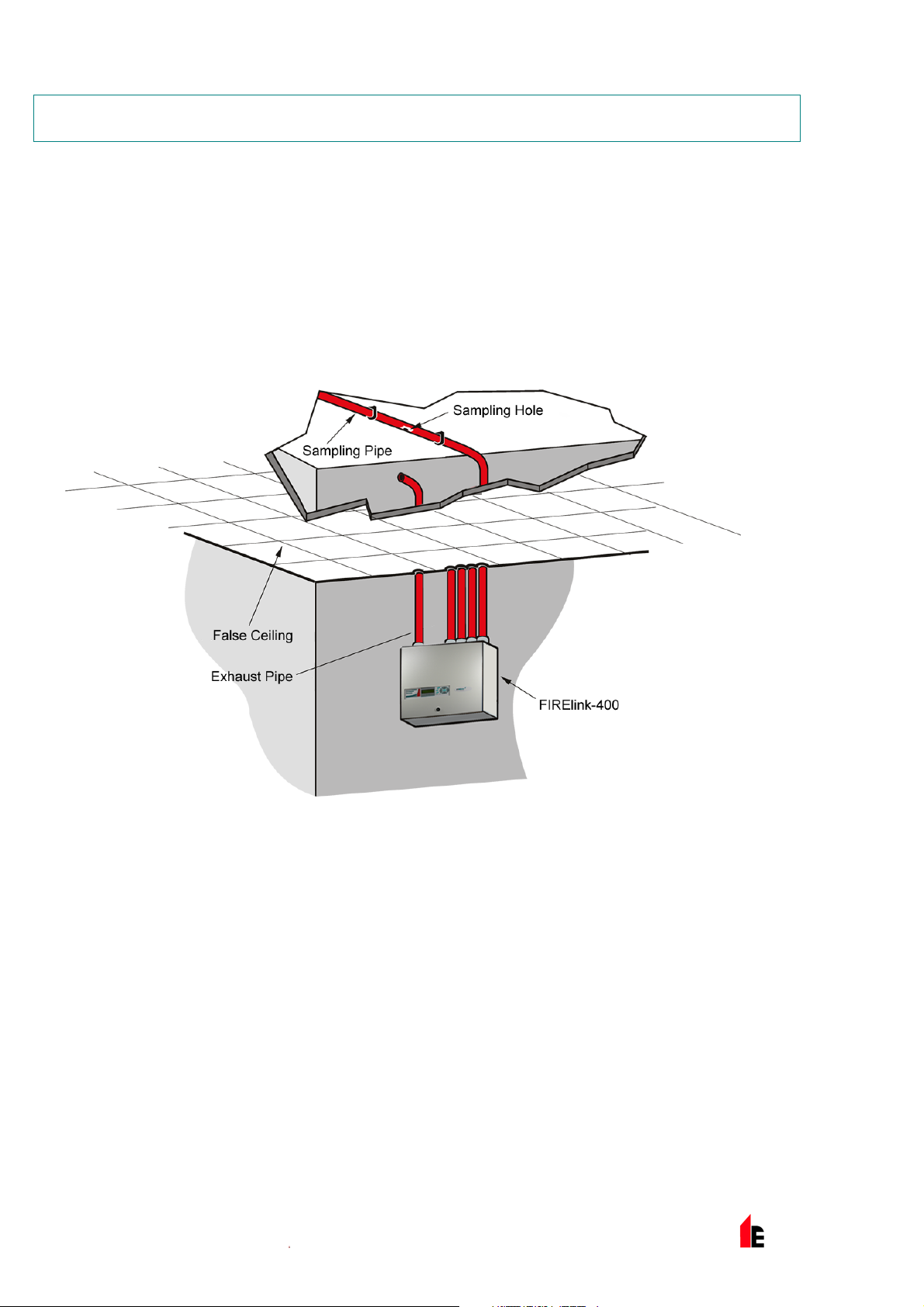
5 Sampling Pipe Design
Aspirating system design is inherently simple. It is often possible to achieve good system performance
with very simple installations. There are however a few rules which must be adhered to, and these rules
are equally applicable to all aspirating systems which operate on similar principles to FIRElink-400. The
information contained in this Handbook is intended as an overview only. For further information please
see the complete System Design Guide.
Do not expect one detector to achieve good performance if sampling from areas of different air
pressure (typically: underfloor air plenums and room spaces or different rooms in air-conditioned
areas). This is because the air pressure differences may cause reverse or poor airflow along the
sampling pipes. If it is not possible to locate the detector within the protected area it may be
necessary to lead an exhaust pipe from the detector exhaust port returning air to the protected
area.
Always locate the sampling points in a position to which smoke may reasonably be expected to
travel. This may sound obvious, but, for example, do not expect ceiling mounted sampling points
to operate satisfactorily if air flow prevents the cool smoke from an incipient fire from reaching
ceiling level. In this instance it is usually better to locate the sampling pipes directly in the airflow
(for example in an air conditioning unit air intake). There is no substitute for carrying out smoke
tests prior to installation of pipes to indicate suitable sampling point location.
To assist in design and to verify system performance, it is advisable to use the FIRElink PipeCAD®
sampling pipe modelling software.
5.1 Pipework
Sampling pipes should be made from a non-hazardous material and should be clearly identified.
a. The ideal internal diameter of sampling pipes is 22mm. Other sizes will often work but will
provide different response times.
b. Ideally, if the total length of sampling pipe is greater than 50 metres, then multiple pipes should
be used. When using multiple sampling pipes, care should be taken to achieve a reasonable
degree of balance (say within 10% of airflow) to ensure even suction from the pipes.
© 2010 Hochiki Europe (UK) Ltd
9-5-0-346/ISS4/OCT10
Page 29

FIRElink-400 Air Sampling System – Installation Manual Page 29 of 58
c. Maximum recommended total sampling pipe length is 200 metres. In order for the installation to
conform to EN54-20, pipes must conform at least to EN61386-1 Class 1131
NOTE: This is 4 lengths of 50 metres, 3 lengths of 70 metres or 2 lengths of 100 metres.
d. Sampling pipes must have capped ends. The end cap should be drilled with a sampling hole
normally between 4 or 5mm diameter and free from burrs. Sampling holes should normally
be 3-4mm diameter or as calculated by FIRElink PipeCAD and free from burrs. Each pipe
run should not have more than 25 holes. Pipe transit time must not exceed 120 seconds and
an approved type of pipe must be used for installations conforming to LPCB requirements.
When drilling holes in the sample pipes, or cutting off lengths of pipe, ensure that all swarf
and debris is removed from the pipe.
This guide holds true for average sampling pipe lengths, but if using long pipes (typically
more than 60 metres total), performance may be improved by making the sampling holes
near the ends slightly larger than those nearer the detector.
Although by no means essential, it must be recommended that if in doubt, FIRElink
PipeCAD® be used to ensure that transit times, balance of suction and individual sampling
point sensitivity are within desired limits.
© 2010 Hochiki Europe (UK) Ltd
9-5-0-346/ISS4/OCT10
Page 30

Page 30 of 58 FIRElink-400 Air Sampling System – Installation Manual
6 Installation
6.1 General
Before installing the detector the local standards for installation of aspirating detection systems must be
consulted as these standards differ throughout the world. Specific advice for one country may not be
applicable to another. The following is a brief set of guidelines on installing detectors.
The detector will normally be mounted at a level where there is easy access to the unit for
configuration and programming.
Unused sampling pipe inlets must be closed. For advice on pipe layout design consult the ‘System
Manual’ and contact the Hochiki Europe (UK) Limited Product Support Department in case of
difficulty (see page 2).
The exhaust air from the unit must not be impeded in any way. If the unit is mounted in a different
air pressure from where the air is being sampled (for example an air duct), then a pipe must be
taken from the exhaust port back to the same air pressure zone as the sampling holes.
All signal cables must be screened and must be of a suitable type. The specific type of cable will
normally depend upon the local fire regulations.
The unit must not be placed in areas where either the temperature or humidity is outside the
specified operating range.
The unit should not be placed in close proximity to any equipment expected to generate high Radio
Frequency levels (such as radio alarms) or units generating high levels of electrical energy (such
as large electric motors or generators).
Ensure that when the detector is fitted to the wall there is enough space on the right hand side to
all allow removal and replacement of the filter element. (see section 11 “Maintenance” on page 52).
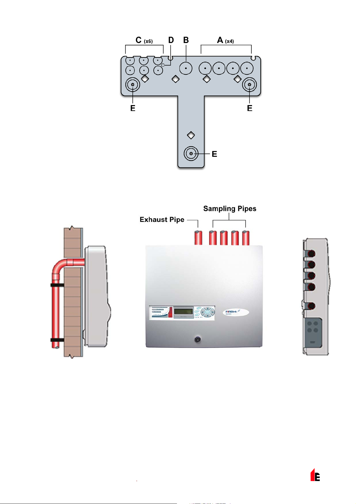
6.2 Mechanical Installation
The detector body is fitted to a wall-mounting bracket which is attached to the wall via the mounting holes
E as shown below. The detector is then fitted over the mounting stud D and secured inside the detector
body with the nut provided for the purpose.
For a more discreet layout, it is possible to allow the sampling pipes and cables to enter the detector from
the rear (see illustrations below), with the sample pipes and connection cables channelled into the wall.
In order to achieve this, sampling holes A and B need to be opened up to a diameter of 30mm to take the
sampling pipes (A) and the exhaust pipe (B). The holes C need to be opened up to 25mm diameter in
order to take a suitable threaded metal cable gland to provide adequate RF screening for the connection
cables. These modifications are shown in dotted lines below.
The wall will also need to be suitably prepared to allow the mounting plate to sit flush against the wall.
The sampling and exhaust pipes must also extend out of the wall sufficiently to tightly engage in the pipe
entries on the rear of the detector as shown. A good starting point would be 25mm of pipe extending past
the back plate. If the detector then sits proud of the bracket, the pipe excess can be trimmed back in
small increments until the correct fit is achieved.
© 2010 Hochiki Europe (UK) Ltd
9-5-0-346/ISS4/OCT10
Page 31
FIRElink-400 Air Sampling System – Installation Manual Page 31 of 58
Rear Pipe Entry Option Top Pipe Entry Option
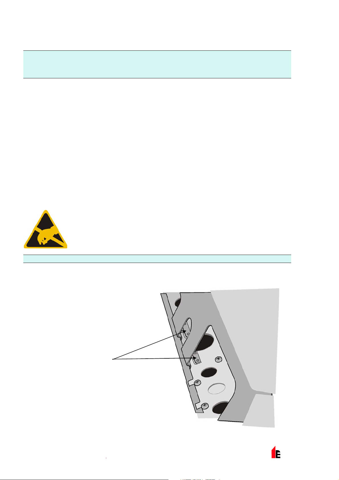
1.1.1 Removal and replacement of the detector front cover
To remove the front cover, unlock it using the key provided (turn anticlockwise). The bottom of the front
cover may then be lifted away from the detector chassis until the top of the cover disengages from the
retaining rails at the top of the chassis. The cover may then be removed.
If greater internal access is required, for example for software upgrades, it may be necessary to remove
the LCD display board. To do this, unfasten the four counter-sunk crosshead screws holding the display
to the display mounting brackets
© 2010 Hochiki Europe (UK) Ltd
9-5-0-346/ISS4/OCT10
Page 32
Page 32 of 58 FIRElink-400 Air Sampling System – Installation Manual
NOTE: It is not necessary to remove the remaining four screws - see sections 2.3 “FIRElink-400 Standard
Detector - Interior View” on page 8, 2.4 “FIRElink-400CM Command Module Detector – Interior
View” on page 9 and 2.5 “FIRElink-CM Stand Alone Command Module – Interior View” on page
10)
Lift the display away from the main board. If the display needs to be completely removed, unplug the
display ribbon connectors from the detector or Command Module main board, taking note of the position
of the connectors which are as follows:
For the Standard Detector (FIRElink-400), a single ribbon cable connected to the detector’s ‘Front
Panel’ display connector (see section 2.3 “FIRElink-400 Standard Detector - Interior View” on page
8).
For the Command Module detector (FIRElink-400CM), a twin ribbon cable, one ribbon connected
to the detector’s ‘Front Panel’ display connector and marked ‘DISPLAY DET’, and one connected
to the Command Module board’s ‘Commander Display’ connector and marked ‘DISPLAY COM’
(see sections 2.4 “FIRElink-400CM Command Module Detector – Interior View” on page 9 and 2.5
“FIRElink-CM Stand Alone Command Module – Interior View” on page 10).
For the stand-alone Command Module, a twin ribbon cable, one ribbon connected to the ‘Detector
Display’ connector and marked ‘COMMAND DET’, and one connected to the ‘Commander Display’
connector and marked ’COMMAND COM’ (see section 2.5 “FIRElink-CM Stand Alone Command
Module – Interior View” on page 10).
When completely removing the display it is recommended that the ribbon connectors
be removed from the main detector or Command Module board rather than from the
display board. When removing these connectors, ensure that suitable antistatic
precautions are taken, for example use of antistatic wrist straps, to prevent possible
static damage to the unit’s electronics. Refitting of the display is the reverse of the
above procedure
NOTE: Ensure that the connectors are refitted as described above.
To refit the front cover, hook the recessed lip at the top of the front cover behind the two retaining guard
rails at the top of the chassis like so:
Guard Rails
© 2010 Hochiki Europe (UK) Ltd
9-5-0-346/ISS4/OCT10
Page 33
FIRElink-400 Air Sampling System – Installation Manual Page 33 of 58
6.3 Electrical Installation
All electrical (power and signal) connections should be made to the green terminal block inside the
detector. Power cables should be screened and of sufficient current carrying capacity. Signal cable
should be 120Ω screened twisted pair such as Belden 9841 24AWG. Power and signal cables should
enter the detector via metal cable glands.
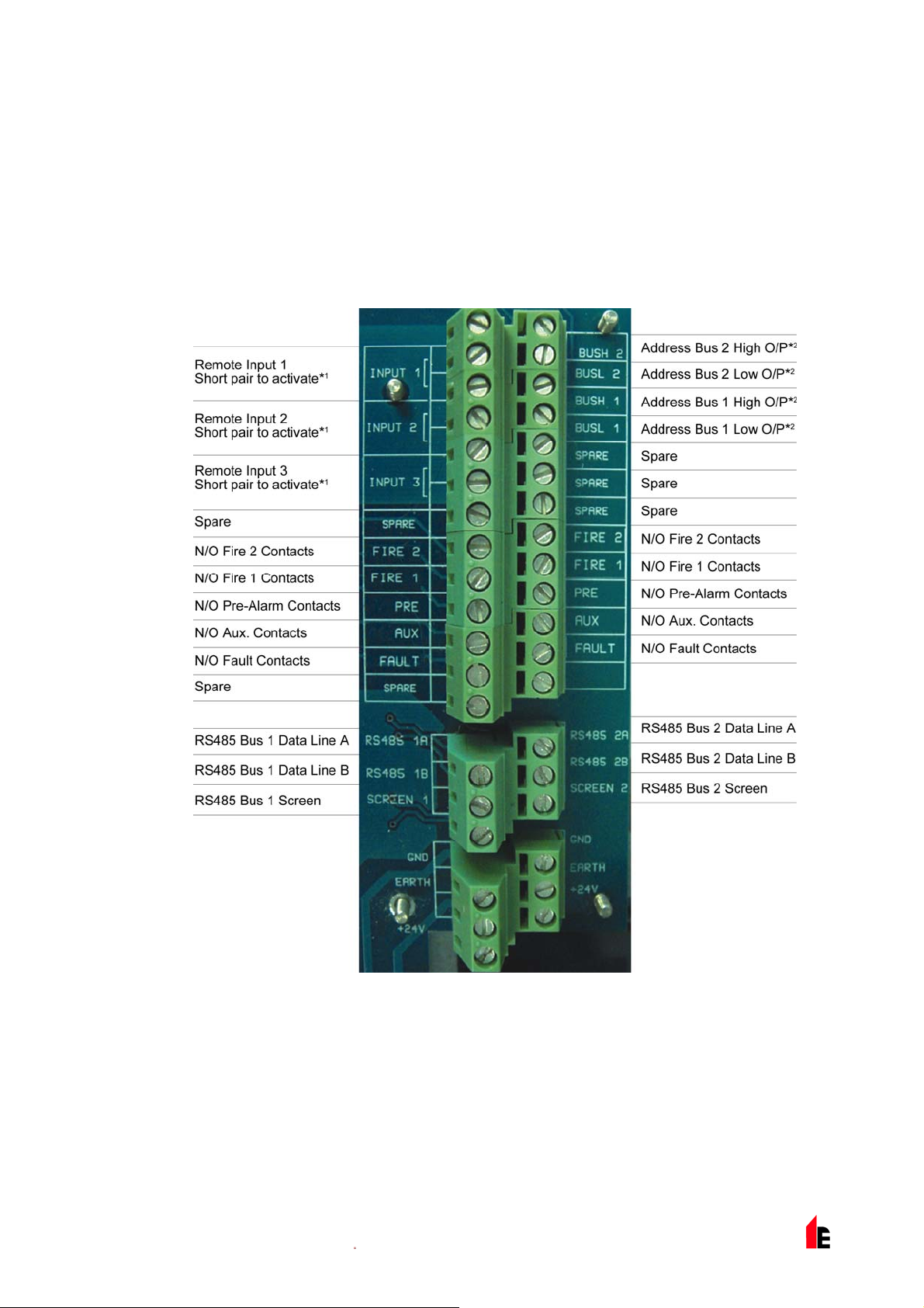
1.1.1 Detector Terminal Block Connections
Terminal block connections are as described below.
N/O = Normally Open, N/C = Normally Closed
1
*
These connections can be used as the input terminals for mains supply and battery fault sensing.
When this is the case, the contacts will signal a fault when the contacts are open rather than
closed, as fault relays operate in the opposite sense to other relays, in other words they are open
for normal operation. The factory default setting is for supply monitoring on ‘I/P 1’.
2
These connections are used to connect a detector to an addressable Fire Panel when the
*
FIRElink-APIC is fitted to the ‘Addressable Interface’ connector on the left hand edge of the detector main
PCB (see section 9.4 “Connecting a Single FIRElink-400 to an Addressable Fire Panel” on page 49).
© 2010 Hochiki Europe (UK) Ltd
9-5-0-346/ISS4/OCT10
Page 34

Page 34 of 58 FIRElink-400 Air Sampling System – Installation Manual
1.1.1 Command Module Terminal Block Connections
All electrical (power and signal) connections should be made to the green terminal block inside the
detector. Power cables should be screened and of sufficient current carrying capacity. Signal cable
should be 120Ω screened twisted pair such as Belden 9841 24AWG. Power and signal cables should
enter the detector via metal cable glands.
Terminal block connections are as described below.
N/O = Normally Open, N/C = Normally Closed
1
*
These connections can be used as the input terminals for mains supply and battery fault sensing.
When this is the case, the contacts will signal a fault when the contacts are open rather than
closed, as fault relays operate in the opposite sense to other relays, in other words they are open
for normal operation. The factory default setting is for supply monitoring on ‘I/P 1’.
2
These connections are used to connect a detector to an addressable Fire Panel when a suitable
*
Universal Addressable Interface card is fitted to the ‘Addressable Interface’ connector on the left
hand edge of the detector main PCB (see section 9.4 “Connecting a Single FIRElink-400 to an
Addressable Fire Panel” on page 49).
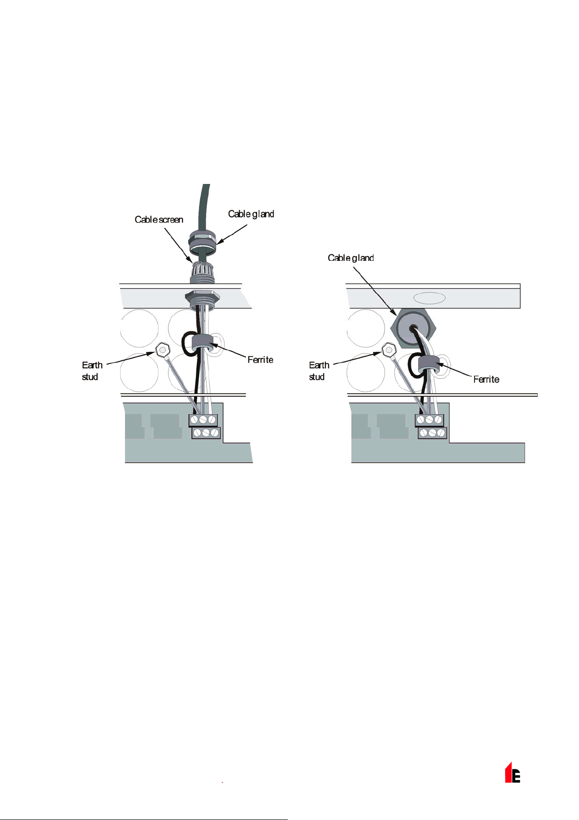
6.4 Connecting Power Cables
For the system to meet full EMC compliance requirements, the following precautions should be taken:
Screened power cable should be used.
The earth wire of power cables should be connected to the detector EARTH terminal, and this in
turn connected to an earth stud on the detector chassis.
© 2010 Hochiki Europe (UK) Ltd
9-5-0-346/ISS4/OCT10
Page 35
FIRElink-400 Air Sampling System – Installation Manual Page 35 of 58
All cables (power and signal) should pass through the screw-in metal cable glands provided. The
screen of the power cable should be terminated at the cable gland.
Power cables need to be fitted with a ferrite ring inside the detector case (2 off provided). The 24V
and 0V wires should be long enough to form a loop around the ferrite wall.
Separate wires from the power cables should be kept as short as possible, just enough to provide
adequate stress relief.
Diagrams below show the appropriate arrangements for top and rear entry cables:
© 2010 Hochiki Europe (UK) Ltd
9-5-0-346/ISS4/OCT10
Page 36

Page 36 of 58 FIRElink-400 Air Sampling System – Installation Manual
6.5 Power Supply Connections
NOTE: The detector may be powered by any EN54-4 compliant monitored 24DC power supply of
sufficient capacity.
1.1.1 Detector Power Supply Connections
1.1.1 Command Module Power Supply Connections
NOTE: The safety earth connection must be separate and not connected to the GND (0V) connection.
1.1.1 Command Module Internal Power Supply
The Command Module may be fitted with an integral power supply and battery charger. The relevant
connections are shown below, although these will normally be made when the unit is manufactured. This
diagram applies only to Command Modules fitted with an integral supply, although connections to
alternative external power supplies will be similar.
© 2010 Hochiki Europe (UK) Ltd
9-5-0-346/ISS4/OCT10
Page 37

FIRElink-400 Air Sampling System – Installation Manual Page 37 of 58
6
5
1
2
3
4
BAT + and – : battery recharge terminals. Bat + (red wire) goes to the positive terminal
1
+ and – : 24V DC supply connecting to the 24VDC and 0V terminals on the Command
2
NC and C : Volt-free fault relay contacts to connect to the "I/P 1" or "I/P 2" terminals on
3
of the first battery and Bat – (black wire) to the negative terminal of the second battery.
The negative terminal of the first battery is connected to the positive terminal of the
second battery with the yellow cable supplied (see section 185619544.01.1.1 “Backup
Batteries” on page 38).
Module terminal block respectively (see section 185619544.01.1.1 “Command Module
Power Supply Connections” on page 36).
the Command Module terminal block (see section 185619544.01.1.1 “Command Module
Terminal Block Connections” on page 34). Polarity of the wires on these terminals is not
important (see section 185619544.01.1.1 “Mains Check Enable (Yes/No - Address 000-
127)” on page 21).
4
Mains supply terminals. This unit should only be powered by mains cable with an earth
5
© 2010 Hochiki Europe (UK) Ltd
24V supply fuse: 5 x 20mm 500mA type.
conductor. Connections are as follows:
Neutral (N): Blue wire (White in U.S)
Earth : Green and Yellow wire
Live (L): Brown wire (Black in U.S)
9-5-0-346/ISS4/OCT10
Page 38

Page 38 of 58 FIRElink-400 Air Sampling System – Installation Manual
6
Mains fuse: For 230V operation, a standard 3A, 5 x 20mm mains fuse.
1.1.1 Backup Batteries
The FIRElink-400 Command Module can be fitted with 2 x 12V, 7 Ah backup batteries to give up to 24
hours’ operation in the event of mains power failure. The integral battery charger can recharge the
batteries to a minimum of 80% capacity within 24 hours of mains reconnection to comply with BS5839
and EN 54 part 4.
These fit under the covers immediately beneath the power supply, which are secured with four screws
each. The batteries are fitted with the supply terminals to the left hand side as viewed from above, with
the cut-out on the cover on the same side. To avoid current surge it is recommended that the batteries
are fitted with the unit powered up.
Batteries are fitted as follows:
Remove the battery covers.
The positive terminal on the battery nearest the power supply is connected to the red wire from the
power supply "BAT +" terminal (see section 185619544.01.1.1 “Command Module Internal Power
Supply” on page 36).
The negative terminal on the first battery is connected to the positive terminal on the second
battery with the yellow battery interconnect wire supplied with the unit.
The negative terminal on the second battery is connected to the black wire from the power supply
"BAT –" terminal.
Replace the battery covers after fitting the batteries.
© 2010 Hochiki Europe (UK) Ltd
9-5-0-346/ISS4/OCT10
Page 39
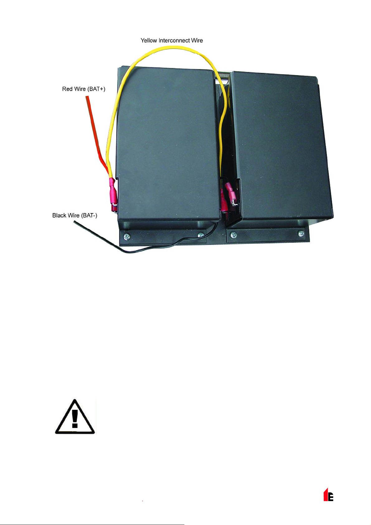
FIRElink-400 Air Sampling System – Installation Manual Page 39 of 58
6.6 Demonstration Mode
In normal use, the detector remains in a reduced sensitivity mode for 24 hours whilst it gathers
information about its environment. For purposes of demonstration, for example, to verify a new
installation, this may be disabled by putting the detector into "Demonstration Mode". This special
operating mode bypasses the 24-hour learning process and allows the detector to operate at a high
sensitivity after only 15 minutes learn time.
To enter Demonstration Mode, the detector must be in FastLearn mode. Whilst FastLearn is running,
hold down the front panel <RESET> button and whilst holding this, simultaneously press the <TEST> and
<ISOL> buttons. The <RESET> and <ISOL> buttons do not need to be enabled for this function.
When entering Demonstration Mode, the detector front panel LCD display will show the legend
mode and the time and date on which this was invoked.
Demonstration Mode should only be used for demonstrations. It should not be used as
a substitute for normal operation as the alarm settings in this mode are based solely on
the sparse data gained during the 15-minute FastLearn period. Over time, this would
lead to nuisance alarms due to normal variation in the detector’s environment. To
cancel Demonstration Mode, invoke a new FastLearn (see section 185619544.01.1.1
IMPORTANT
NOTE
“Start / Stop FastLearn (Yes/No - Address 001-127)” on page 18).
Demo
© 2010 Hochiki Europe (UK) Ltd
9-5-0-346/ISS4/OCT10
Page 40

Page 40 of 58 FIRElink-400 Air Sampling System – Installation Manual
6.7 EN54-20 Compliance
The installation must be designed using PipeCAD software, which is provided free on the CD shipped
with each detector. After designing the installation including pipes, endcaps and sampling holes, enter
the detector type in the “Type” drop-down list in “Options” “Calculation options”.
Select “Options” “Calculate” or click on the calculator icon. The software will prompt you to choose from
“Use set hole sizes” “Best flow balance” and “Max. permissible transit time”. Select the appropriate option
and click “OK”. The results for each pipe (“View” “Results”) show calculations for each sampling hole on
the pipe with the nearest to the detector at the top of the screen, and the endcap hole at the bottom.
“Transit time” shows the smoke transit time to the detector from each sampling hole. For EN54-20, this
must be below 120 seconds from every hole.
The column headed “Hole sensitivity % obs/m” shows the predicted sensitivity for each hole. For the
installation to comply with EN54-20, depending on the class of installation, each sampling hole must be
no less sensitive than the following:
Class A: 0.62% obs/m
Class B: 1.95% obs/m
Class C: 4.65% obs/m
The calculation can be further refined by leaving a working detector in the protected area for at least
24hrs at the intended alarm factor for the installation (this could be done before or after installation). The
detector sensitivity can be read from the “Sensitivity” figure on the histogram screen of the Remote
software supplied with each detector. Enter this figure into the PipeCAD calculation under “Options”
“Calculation options”. “Detector sensitivity”. Clicking on “OK” will update the hole sensitivities to the figure
expected for the actual layout.
Commissioning and periodic system tests must involve smoke tests to verify that the system performs as
expected and enters Fire 1 alarm within 120 seconds from the farthest hole. The detector sensitivity must
also be inspected to ensure it has not radically fallen from the installed figure. If it has changed for any
reason the new figure must be re-entered into PipeCAD and the recalculated hole sensitivities must be
confirmed to be within the class limits shown above.
The settings of a compliant system should be recorded, as it is possible by changing certain
programmable functions to make the system non-compliant. If functions are changed, it is recommended
that the system is retested if continuing compliance is in any doubt.
For EN 54-20 compliant installations the detector requires that the flow thresholds be
set manually to ±6% of the nominal value, after the FastLearn phase is completed. For
example, if the flow rate is 64% after the completion of the FastLearn period, the user
must manually set the low flow threshold to 58% and the high flow threshold to 70%.
IMPORTANT
NOTE
© 2010 Hochiki Europe (UK) Ltd
9-5-0-346/ISS4/OCT10
Page 41

FIRElink-400 Air Sampling System – Installation Manual Page 41 of 58
7 External Communications
7.1 BMS Protocols on the FIRElink-400 Command Module
The Command Module of the FIRElink-400 has a second RS232 port that can be used to send messages
to a pager or compatible GSM phone using a modem or to enable connection to a Building Management
System (BMS). This comprises the terminals "RS 232 Tx" (transmit), "RS 232 Rx" (receive) and "GND"
on the green terminal block inside the unit (see section 185619544.01.1.1 “Command Module Terminal
Block Connections” on page 34).
Set-up of the Command Module is done using three functions;
185619544.01.1.1 on page 23,
Page on Fault (see section 185619544.01.1.1 on page 25) and
BMS Protocol (see section
Page on Alarm (see section 185619544.01.1.1 on page 25).
When either
exclusively for paging purposes by setting
Programmable function
serial port to communicate with the BMS. Setting
paging) will disable functions
BMS Protocol numbers are as follows:
Page on Fault or Page on Alarm is enabled the second serial port is reserved
BMS Protocol to 0 (TAP paging).
BMS Protocol sets the communications format that is used by the second
BMS Protocol to anything other than 0 (Tap
Page on Fault and Page on Alarm if they are enabled.
Protocol Number Protocol
0 TAP Paging (default)
1 Output only. Events are sent in the same ASCII text
format as the internal event log display. This may be
used to drive a serial printer if required.
2 BACnet ANSI/ASHRAE standard 135-1995.
1.1.1 Text Output Support (Protocol 1)
Text is output at 9600 baud, 8 bit with no parity. When an event occurs the event is printed in the
following format:
Device 'Command Module' or 'Detector n'
Event 'Fire 1'
Timedate 10:32 21/03/2001
1.1.1 BACnet Support (Protocol 2)
The Command Module models the attached detectors as analogue value object types instances 2 to 128.
The Command Module status is stored as analogue value instance 1. The Present_Value property of the
analogue objects can have one of the following values; 0 = Disabled; 2 = Fault; 32 = Normal; 48 =
PreAlarm; 64 = Fire 1; 128 = Fire 2.
© 2010 Hochiki Europe (UK) Ltd
9-5-0-346/ISS4/OCT10
Page 42

Page 42 of 58 FIRElink-400 Air Sampling System – Installation Manual
The device object supports the following
Properties:
Object_Identifier
Object_Name
Object_Type
System_Status
Vendor_Name
Vendor_Identifier
Model_name
Firmware_Revision
Application_Software_Version
Protocol_Version
Protocol_Conformance_Class
The following Properties are supported by
the analogue value objects:
Object_Identifier
Object_Name
Object_Type
Present_Value
Status_Flags
Event_State
Out_Of_Service
Units
Protocol_Services_Supported
Protocol_Object_Types_Supported
Max_APDU_Length_Accepted
Segmentation_Supported
APDU_Timeout
Number_Of_APDU_Retries
For further information on BACnet implementation consult the FIRElink-400 Technical Manual or contact
the Hochiki Europe (UK) Limited Product Support Department (see page 2).
1.1.1 Paging from the Command Module
The FIRElink-400 Command Module has the facility to send text messages to alphanumeric pagers or
SMS messages to some mobile phones.
In order to send messages to a pager or similar device a modem must be plugged into the RS232TX and
RS232RX terminals of the Command Module using a suitable cable.
The call centres of the pager or SMS-capable phone must support the TAP protocol. In the UK Cellnet
phones and BT pagers have this facility, amongst others. Please contact your pager provider to check
whether they provide access with the TAP protocol.
1.1.1 Configuring the software
No manual configuration of the modem is required as the command module configures the modem
automatically on dialling.
© 2010 Hochiki Europe (UK) Ltd
9-5-0-346/ISS4/OCT10
Page 43

FIRElink-400 Air Sampling System – Installation Manual Page 43 of 58
The command module has three entries used to send messages. They are described below with an
example for a BT pager. The functions may be found in
Setup menu > Pager.
Call centre
Password
Pager
This is the phone number the modem dials up to send a message. For the BT
EasyReach service this number is 09011130000.
This is an optional password used to access the system. BT EasyReach does not
use the password so leave this entry blank.
This is the number of the actual pager. This number will be detailed in the pager or
SMS phone documentation.
© 2010 Hochiki Europe (UK) Ltd
9-5-0-346/ISS4/OCT10
Page 44

Page 44 of 58 FIRElink-400 Air Sampling System – Installation Manual
8 Event Log
An event is defined as operation of any of the front panel controls (when enabled), a signal received from
a remote source (for example, the Command Module or PC), a detector level exceeding the Aux., PreAlarm, Fire 1 or Fire 2 thresholds or certain commands sent from the remote software or SenseNET.
The event log will also store items such as day and night start times, demonstration mode, power fault,
detector fault etc. The detector keeps a log of the last 200 events for reference purposes.
The event log can be downloaded using a PC that has the remote software installed and is connected to
the FIRElink-400’s RS 232 port using a serial cable (see section 9.5 “Connecting to a PC” on page 49).
The event log can also be viewed in the
the last recorded event is printed out first.
When the buffer that stores events is full (200 events are stored) and a new event occurs, the oldest
event in the buffer is discarded.
Log menu, which prints out the event log in reverse order i.e.
© 2010 Hochiki Europe (UK) Ltd
9-5-0-346/ISS4/OCT10
Page 45

FIRElink-400 Air Sampling System – Installation Manual Page 45 of 58
9 Interfacing
Because of the flexible nature of the FIRElink-400 detector and the many possible configurations, there
are many options for interfacing the detectors to the Fire Panel. These include many third party
interfaces available from various manufacturers. Because of this, it is not possible to give a complete list
of all interfacing methods but the following pages will give details of the most common methods that are
likely to be used.
9.1 Setting the Detector Address
In order to identify itself to the Command Module or fire panel, each detector needs to have a unique
address ranging from 1 to 127. The detector address is simply set on the red DIP switch SW1 at the
bottom left of the opened detector on the main circuit board. The switch settings are up for 1 and down
for 0, and the detector address is set as a 7-bit binary code (switch 8 equates to a value of 128 and so is
outside the usable address range). An example is shown below:
The address equates to 01100011 in binary, or (1 x
1) + (1 x 2) + (0 x 4) + (0 x 8) + (0 x 16) + (1 x 32) +
(1 x 64) + (0 x 128) = 99.
The full range of available addresses and their relevant switch settings are shown below:
© 2010 Hochiki Europe (UK) Ltd
9-5-0-346/ISS4/OCT10
Page 46

Page 46 of 58 FIRElink-400 Air Sampling System – Installation Manual
9.2 Connecting a Detector Network to a Command Module
120 ohm screened twisted pair such as Belden 9841 24 AWG should be used for all loop connections.
The RS485 A and B wires should be taken through a ferrite (supplied) with a single loop, illustrated for the
power wires in section 6.4 “Connecting Power Cables” on page 34. The total length of interconnecting
cable between adjacent FIRElink-400 detectors in the loop should not exceed 1.2 kilometres.
The detectors are connected using the RS485 connections on the terminal block (see sections
185619544.01.1.1 “Detector Terminal Block Connections” on page 33 and 185619544.01.1.1 “Command
Module Terminal Block Connections” on page 34). RS485 1A and 1B are the signal connections for bus
1 and RS485 2A and 2B are the signal connections for bus 2. SCREEN 1 and 2 are the screen
connections for buses 1 and 2 respectively.
For the Command Module, the RS485 1A and 1B connections may be thought of as the ‘Send’ lines, and
2A and 2B the ’Return’ lines. For each detector on the loop, the 1A and 1B connections may be thought
of as the lines from the previous detector on the loop and the 2A and 2B connections the lines to the next
detector in the loop.
1.1.1 Fault Tolerant Detector Loop Configuration
It should be pointed out that loop connections such as above are only needed for a fully fault-tolerant
network where full isolation is required between detectors. If all detectors are operating within the same
zone a series connection can be used where the output from the Command Module is taken from the Bus
2 terminals and the last detector in the loop does not require to be connected back to the command
module as shown below.
In this example, the Command Module will not be able to monitor the network for communications
problems but less wiring is required.
© 2010 Hochiki Europe (UK) Ltd
9-5-0-346/ISS4/OCT10
Page 47

FIRElink-400 Air Sampling System – Installation Manual Page 47 of 58
1.1.1 Non Fault Tolerant Serial Configuration
9.3 Connecting a Command Module to an Addressable Fire
Panel
When a Command Module is being used to manage one or more detectors (the maximum limit is 127)
then a Addressable Programmable Interface Card (FIRElink-APIC) may be used to decode detector
status information in the Command Module and relay to the Fire Panel via the Addressable Bus 1 and
Bus 2 terminal block connections (see section 185619544.01.1.1 “Command Module Terminal Block
Connections” on page 34).
In this configuration only one interface is required and all detector information is available through this
interface, one address per device.
© 2010 Hochiki Europe (UK) Ltd
9-5-0-346/ISS4/OCT10
Page 48
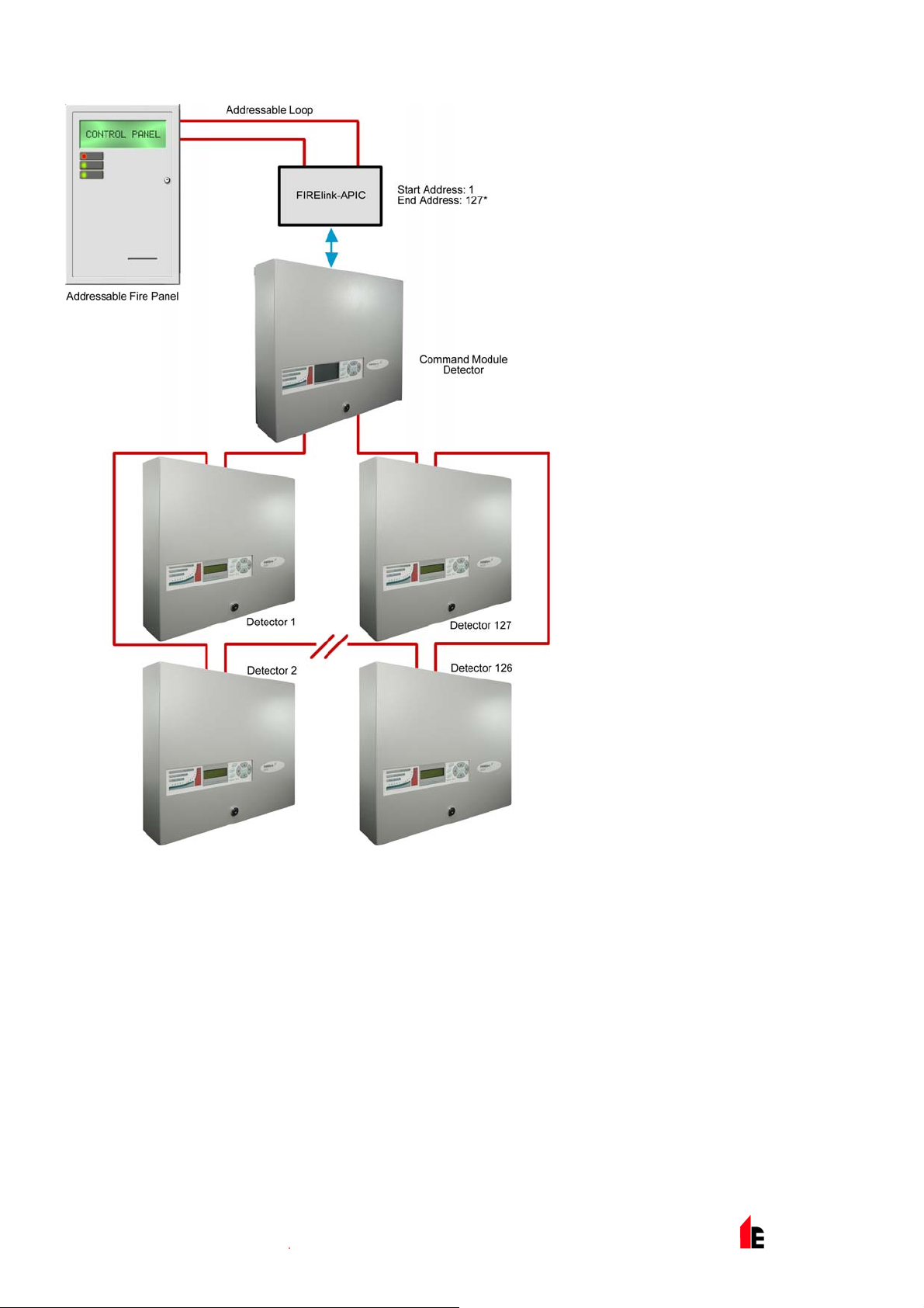
Page 48 of 58 FIRElink-400 Air Sampling System – Installation Manual
*It is not essential in networks
of less than 127 detectors that
a continuous unbroken range
of detector addresses is used,
merely that all addresses are
different and that the full
range of addresses is set on
the FIRElink-APIC. However,
any unused addresses would
then show up on the fire panel
as in fault (detector not
present). It is therefore
recommended that, when
using the FIRElink-APIC to
communicate to a fire panel,
an unbroken range of detector
addresses is employed.
© 2010 Hochiki Europe (UK) Ltd
9-5-0-346/ISS4/OCT10
Page 49

FIRElink-400 Air Sampling System – Installation Manual Page 49 of 58
9.4 Connecting a Single FIRElink-400 to an Addressable Fire
Panel
An FIRElink-APIC may be used to decode detector status information and relay this to the Fire Panel via
the Addressable Bus 1 and Bus 2 terminal block connections (see section 185619544.01.1.1 ”Detector
Terminal Block Connections” on page 33).
NOTE: The detector
address on the
RS485
communications loop
and the Fire Panel
addressable protocol
address are the
same, in other
words, no address
translation is
performed.
9.5 Connecting to a PC
To connect a single stand-alone detector to a PC, connect the PC‘s serial port directly to the detector‘s 9way RS232 port. Connections for this cable are shown below:
© 2010 Hochiki Europe (UK) Ltd
9-5-0-346/ISS4/OCT10
Page 50
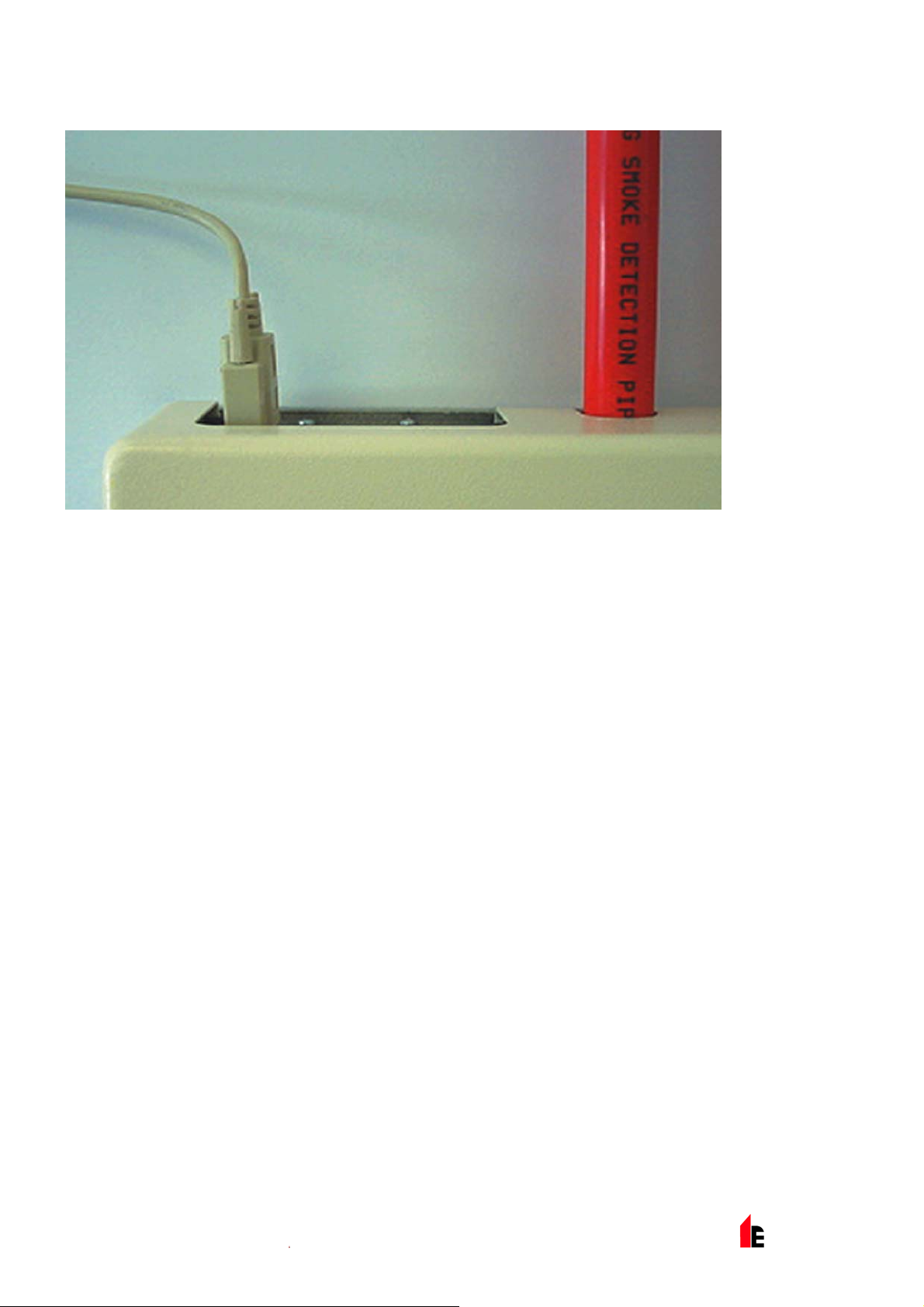
Page 50 of 58 FIRElink-400 Air Sampling System – Installation Manual
When multiple detectors are networked together and a Command Module is being used, the PC connects
to the Command Module‘s 9-way RS232 port. The cable connections are the same as the Standard
Detector cable connections.
© 2010 Hochiki Europe (UK) Ltd
9-5-0-346/ISS4/OCT10
Page 51

FIRElink-400 Air Sampling System – Installation Manual Page 51 of 58
10 Commissioning
Before commissioning the detector the local standards of aspirating detection systems must be consulted.
These standards differ widely throughout the world and specific advice for the market in one country may
not be applicable to another.
Commissioning strategy will initially depend upon the environment in which the detector is installed. For
instance, the test for a computer room (which should be a relatively clean environment) would be very
different from, say, a flour mill, which would probably have a high level of airborne particulate content.
A widely accepted standard for computer rooms/EDP areas is British Standard BS6266, equipment
overheating at a stage well before combustion. To perform the test electrically overload a 1 metre length
of PVC insulated wire of 10/0.1mm gauge for one minute using an appropriate power supply. The
detector has two minutes from the end of the wire burn to give an alarm indication.
For areas with higher levels of background particulate matter testing methodology would be similar to that
of standard point detectors.
10.1 Commissioning Checklist
The following brief checklist allows quick setup of the detector. This procedure will be adequate for most
standard installations.
1. Before powering up the detector, visually check all cabling to ensure correct connection. If wire
identification is not immediately clear (for example, by use of different coloured wires or wire
identification sleeves) an electrical check should be made.
NOTE: Any damage caused by misconnection of the detector is not covered by warranty.
2. Power up the unit and enter the engineering access code. The factory default setting for this is
3. Enter the
185619544.01.1.1 “Time and Date (Numeric – Address 000-127)” on page 16).
4. Set an appropriate alarm factor for the protected environment. The detector will perform a
FastLearn for the new alarm factor (see section 185619544.01.1.1 “ClassiFire® Alarm Factor
(Numeric - Address 001-127) on page 17).
5. Whilst the detector is still in FastLearn mode exit the program mode on the display by pressing
<RESET> and set the detector into demonstration mode (see section 6.6 “Demonstration Mode”
on page 39). To do this, press and hold down the <RESET> button and simultaneously depress
the <TEST> and <ISOL> buttons. The text display will then display
and date.
0102. See section 4.1 “Engineering Access Code” on page 14 for further details.
Setup menu and verify that the time and date are correct. (see section
Demo mode and the time
6. Wait for the FastLearn to finish (when the legend
and the ‘rolling‘ LED indications will finish) and perform any necessary smoke tests, ensuring that
the detector reacts appropriately, and let the smoke fully dissipate.
7. Perform another FastLearn, this time not putting the detector into demonstration mode. The
detector will generate no alarms during the 15 minute FastLearn period, and after this the
detector will operate at a reduced sensitivity for 24 hours whilst ClassiFire acclimatises to the
protected environment and sets up appropriate day and night sensitivity settings.
© 2010 Hochiki Europe (UK) Ltd
9-5-0-346/ISS4/OCT10
FastLearn end will appear on the display
Page 52
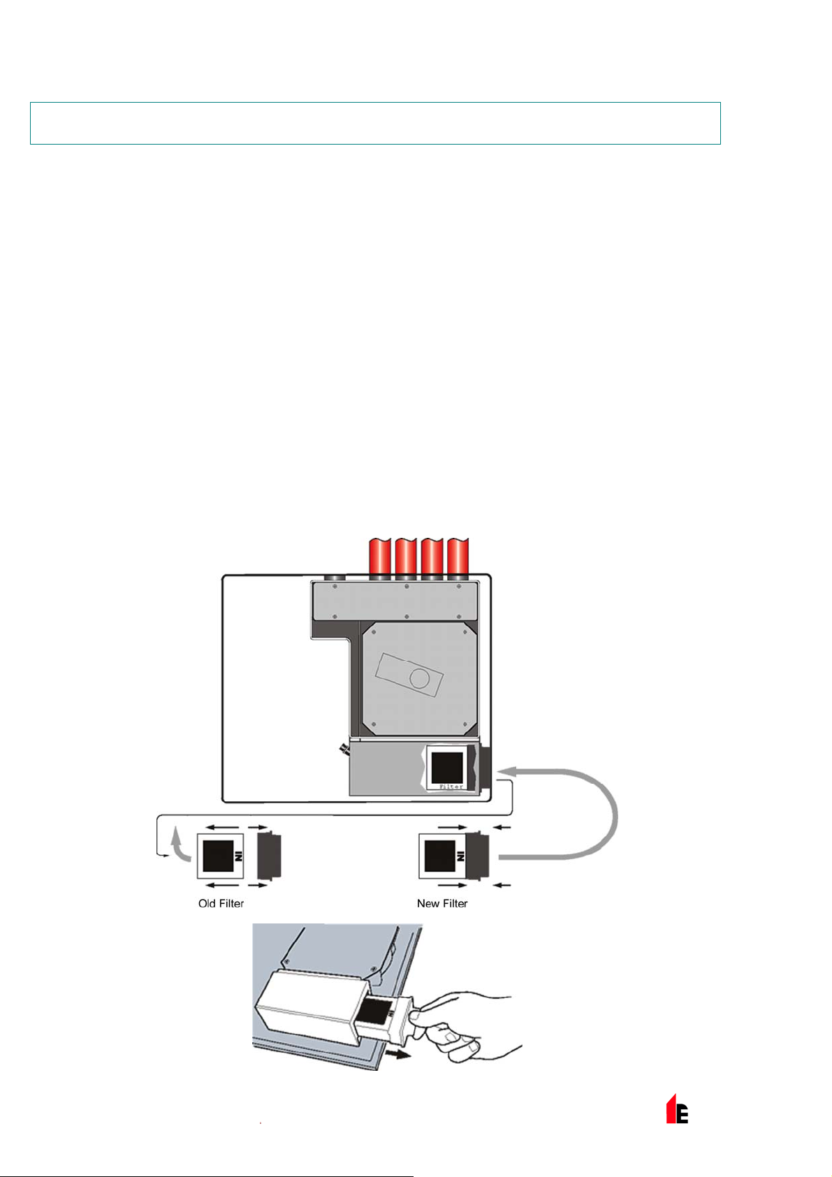
Page 52 of 58 FIRElink-400 Air Sampling System – Installation Manual
11 Maintenance
FIRElink-400 range is a very low maintenance detection system. If required, external cleaning of the unit
should be performed using a damp (not wet) cloth. Do not use solvents as these may mar the display
bezel. The only part that may require field replacement during servicing is the dust separator assembly.
The dust separator condition can be checked using the
Diagnostics menu, which gives a percentage reading of dust separator efficiency. When this
level drops to 80% the detector will signal a
need replacing.
As dust contained in the dust separators may expose maintenance personnel to a ‘Nuisance Dust‘ hazard
as defined by the ‘Control of Substances Hazardous to Health‘ (COSHH), it is strongly recommended that
suitable masks and protective clothing be worn when changing filters. Used separators are not intended
for re-use and should be disposed of.
The following illustration shows how the dust separator is replaced. Make sure to push the separator fully
home, or the detector will fail to register its presence, and will continue to indicate Separator change .
Open the front cover using the key provided, and locate the dust separator tab at the bottom right of the
detector as shown. Remove the black end piece with the removal tab from the filter element and dispose
of the element. Fit the new element into the plastic end piece and slide into the detector. The filter
should be fitted with the legend ‘IN’ towards the front of the detector. If the filter is inserted the wrong way
up, the detector will not register its presence and the Separator change legend will stay on the display.
When the replacement filter is fitted, the detector will automatically start a FastLearn routine.
Separator renew fault and the dust separator will
Dust Separator test in the
© 2010 Hochiki Europe (UK) Ltd
9-5-0-346/ISS4/OCT10
Page 53

FIRElink-400 Air Sampling System – Installation Manual Page 53 of 58
12 Troubleshooting
12.1 Pressing RESET or ISOL. Button Has No Effect
Check that the controls have been enabled. These functions are disabled by default (see section
185619544.01.1.1 “Reset, Test & Isolate Button Enable/Disable (Yes/No - Detectors 000-127)” on
page 21)
12.2 Nuisance Alarms Occur Too Often
Check that the ClassiFire alarm factor setting is appropriate for the normal working environment of
the protected area (see section 185619544.01.1.1 “ClassiFire® Alarm Factor (Numeric - Address
001-127) on page 17).
Check that the detector is not in Demonstration mode. This can be ascertained by viewing the
event log (see section 185619544.01.1.1 “View Event Log (Display - Address 000-127)” on page
25 and section 8 “Event Log” on page 44) and checking that the entry
log entry number than the most recent
Remember that the log entries are in reverse order, with the most recent entries appearing first.
FastLearn start and FastLearn end entries.
Demo mode has a higher
If the log shows that Demonstration mode was invoked during the last FastLearn period, start a
new FastLearn and allow it to complete its 24-hour cycle (see section 185619544.01.1.1 “Start /
Stop FastLearn (Yes/No - Address 001-127)” on page 18).
From the event log (see section 185619544.01.1.1 “View Event Log (Display - Address 000-127)”
on page 25 and section 8 “Event Log” on page 44) check that 24 hours have elapsed since the last
FastLearn end entry.
Check that day-night switchover times are appropriately set to reflect active and non-active periods
(see section 185619544.01.1.1 “Hour Start of Day and Night Operation (Numeric - Address 001-
127)” on page 18).
12.3 Elevated Smoke Levels Do Not Generate Alarms
Check that detector is not Isolated or in FastLearn (if Isolated, the Fault light will be lit)
Check that the detector sampling points are in the smoke stream
Check that unused sampling pipe ports are closed and that sampling pipes are firmly and cleanly
seated in their ports and undamaged
Check that the correct ClassiFire alarm setting has been set (see section 3.4.5)
Check that the detector has either had a 24 hour learning period or that it has been placed in
demonstration mode.
12.4 Low Mean Output
Check that the filter does not require changing (see section 185619544.01.1.1 “Dust Separator
Condition (Display - Address 001-127)” on page 26) and that the air plenum chamber is clean. The
chamber may become clogged when, for example, heavy building activity has occurred near the
sampling pipes. If so, the chamber may require factory service. The detector is not designed to
handle large quantities of coarse debris and dust.
© 2010 Hochiki Europe (UK) Ltd
9-5-0-346/ISS4/OCT10
Page 54

Page 54 of 58 FIRElink-400 Air Sampling System – Installation Manual
12.5 Detector Sensitivity Varies Over Time
There are many reasons why particle densities may vary, and the ClassiFire system automatically
compensates for this in order to replace the likelihood of nuisance alarms due to normal variations
in background smoke density. Within limits set by the ClassiFire alarm factor, this is a normal part
of the detector‘s working.
12.6 Flow Fault Errors
These occur when the airflow rate into the detector exceeds the pre-programmed parameters. As the
detector ‘learns‘ the flow setup from the initial installation, this usually means that there has been some
change in conditions. A Flow high fault may indicate that a sampling pipe is damaged, and a Flow low
fault may indicate that the pipe has been blocked, for example, by nearby building operations.
If the detector input is sampled from one area and the exhaust is in another area with different
pressure (for example, the detector is in a roof space and sampling from an enclosed room), this
may lead to flow faults. In this case it would be necessary to lead a pipe from the exhaust to the
protected area to ensure nominal flow.
1.1.1 "Low flow" Error Messages.
Check that the pipe giving the error is not blocked
Check that, if the pipe is unused, the flow sensor for this pipe has been disabled (see section
185619544.01.1.1 “Airflow Monitoring (Display / Numeric - Address 001-127)” on page 22).
Check that the low flow fault threshold is not set too high (see section 185619544.01.1.1 “Airflow
Monitoring (Display / Numeric - Address 001-127)” on page 22).
Consider increasing the aspirator (fan) speed (see section 185619544.01.1.1 “Aspirator Speed
(Numeric - Address 001-127)” on page 21).
1.1.1 "High flow" Error Messages
Check that the pipe is pushed home into the inlet and is not broken or cracked
Check that installed pipework is fitted with an endcap. Hochiki’s FIRElink PipeCAD® pipe
modelling software prompts the use of appropriate endcaps. Open bore pipes are not
recommended.
Check that the high flow fault threshold is not set too low (see section 185619544.01.1.1 “Airflow
Monitoring (Display / Numeric - Address 001-127)” on page 22).
Consider reducing the aspirator (fan) speed (see section 185619544.01.1.1 “Aspirator Speed
(Numeric - Address 001-127)” on page 21).
12.7 Cannot Refit the Front Cover
Check that the recessed top edge of the cover is securely located behind the locating guard rails
on the chassis (see section 185619544.01.1.1 “Removal and replacement of the detector front
cover” on page 31).
Check that the key is turned to the unlocked position (anticlockwise)
© 2010 Hochiki Europe (UK) Ltd
9-5-0-346/ISS4/OCT10
Page 55

FIRElink-400 Air Sampling System – Installation Manual Page 55 of 58
12.8 No Display
Check that the display ribbon cable is securely connected to the detector/ command module main
board and to the display board as appropriate. (see section 185619544.01.1.1 “Removal and
replacement of the detector front cover” on page 31).
Check that the display ribbon cable has not been damaged.
© 2010 Hochiki Europe (UK) Ltd
9-5-0-346/ISS4/OCT10
Page 56

Page 56 of 58 FIRElink-400 Air Sampling System – Installation Manual
13 Error Messages
The FIRElink-400 text display can provide a wide range of information about the detector. A list of error
messages follows with a brief explanation of their meanings.
Separator renew
Separator change
Bad value
Bad time
Bad date
Bad detector :
No response
001 W x X 002
Loop break
Comms fault
The dust separator requires replacement. See section 11
“Maintenance” on page 52.
The dust separator is missing or improperly fitted. See section 11
“Maintenance” on page 52.
A value has been input into a function, which is outside the parameter
range for that value. Take note of the range of values allowed (in
brackets) and try again.
A detector address has been entered which is either outside the
allowed range or which is not present on the loop. This may also
happen if the user has entered address 000 (command module) for a
function which it does not support (for example, alarm factor).
The Command Module has unsuccessfully attempted to read a
function value from a connected unit. Check that the unit connected
supports this function.
There is a break in the communications loop between the detector
addresses specified. Check the wiring.
The Command Module has polled a detector and no response has
been received after the specified poll timeout value. See section
185619544.01.1.1 “Poll Timeout (Numeric - CM only)” on page 24
Bad access code
Battery fault
Watchdog reset
Detector fault
An incorrect access code has been entered. Enter the correct code.
This indicates either that the standby battery has discharged to a
predetermined level or that no standby battery is fitted. In the former
case, the battery should be replaced and recharged. In the latter
case, the battery check should be disabled (see section
185619544.01.1.1 “Battery Check Enable (Yes/No - Address 000-
127)” on page 21). It is important that the battery fault be acted upon
as soon as noticed, as excessive discharge may cause damage to
the battery. The battery fault condition comes on before the battery
reaches this portion of the discharge curve.
This indicates that there has been a power supply fault. If there are
frequent power outages it may be advisable to power the unit from a
UPS.
This indicates that there is a problem with the detector head. This
may be due to a number of causes. Refer to the chart readout if this
can be downloaded to a PC and note the detector signal level at the
time of the fault. When as much information as possible has been
determined about the conditions at the time of the error, please
contact the Hochiki Europe (UK) Limited Product Support Department
(see page 2).
© 2010 Hochiki Europe (UK) Ltd
9-5-0-346/ISS4/OCT10
Page 57

FIRElink-400 Air Sampling System – Installation Manual Page 57 of 58
14 Do's and Don’ts
DO:
Ensure that the ClassiFire alarm factor is appropriately set.
Ensure that power and signal cables are correctly connected before powering up by use of cable
identifiers or electrical continuity checks. Incorrect connection could damage the detector.
Ensure that cable of an appropriate approved type is used for interconnection.
Place sampling points so that the detector will be able to detect smoke at the earliest opportunity.
Ensure that the detector exhaust is in an area with the same atmospheric pressure as the sampling
pipes, either by placing the detector physically in the protected area or by leading a pipe from the
detector exhaust to the protected area.
Ensure that the environment of the protected area is within the environmental operating parameters
of the detector (temperature -10 to +60°C, (humidity 0-90%, non-condensing).
Close unused pipe inlet ports on the detector to ensure optimal operation.
DON’T
Forget to set the appropriate ClassiFire alarm factor for the area to be detected.
Forget to set the Detector Address Switches correctly when used in a network.
Site detectors in damp or exposed areas.
Remove or connect boards when the detector is powered up.
Connect internal 0 volt terminals to local earth.
Attempt to re-use dust separator cartridges once removed.
Attempt to adjust or alter detector settings other than via the user-programmable functions. In
particular, the setting up of the laser is a precision task, and once set up the potentiometers should
be left alone. If it is suspected that the laser focus has shifted (for example, after dropping the
detector), it should be returned to Hochiki Europe (UK) Limited for recalibration.
Place the detector near high power RF sources.
Place the detector so close to other equipment that there is insufficient room to access and change
the dust separator. See section 11 “Maintenance” on page 52.
Use sampling pipe of less than 27mm outside diameter without a suitable 27mm pipe adapter.
Use excessive force when fitting sampling pipes as this may damage the detector.
© 2010 Hochiki Europe (UK) Ltd
9-5-0-346/ISS4/OCT10
Page 58

Page 58 of 58 FIRElink-400 Air Sampling System – Installation Manual
15 FIRElink-400 Specification
SELV Rating (EN 60950) Class III
21.6Vd.c. - 26.4Vd.c.
Supply Voltage
Size (mm) 427W x 372H x 95D
FIRElink-400 5.2
Weight (kg)
Operating Temperature Range
Operating Humidity Range
Measurement Range (obs/m)
Detection Principle Laser light scattering mass detection
Particle Sensitivity Range 0.0003µm to 10µm
Current Consumption (mA)
Relay Contact Rating 500mA @ 30Vd.c.
Maximum Sampling Pipe Length 200 metres @ 100 sampling holes
Sampling Pipe Inlets 4
Sampling Pipe Internal Diameter 15-25mm
Alarm levels 4 – (FIRE 2, FIRE 1, PREALARM and AUX)
Bargraph Sensitivity Range 0.0015 – 25% Obs/m
Bargraph Segments 26
Chamber Service Intervals Greater than 8 years (depending on environment)
Dust Separator Replacement Intervals Greater than 5 years (depending on environment)
Laser Lifetime (MTTF) Greater than 1000 years
Programming Front Panel or PC via RS232/RS485
Data Bus Cable RS485 data cable
Data Bus Length 1.2 km IN, 1.2km OUT
IP Rating IP50
Supported Languages on Internal Programmer
FIRElink-400CM 5.3
FIRElink-CM 6.2
FIRElink-CM with batteries 10.1
FIRElink-400 470 (fan speed 8)
FIRElink-400CM 920 (fan speed 8)
FIRElink-CM 450
PSU Type: conforming to EN 54-4
Electrical safety complies with IEC 61010-1
0 to +38°C (UL268 compliance)
-10 to +60°C (CEA 4022 compliance)
0 - 90% Non Condensing
IEC 61010-1 Pollution degree 1
IEC 61010-1 Installation Cat. II
0.03% to 25% Full Scale Deflection (FSD)
0.0015% to 25% Sensitivity Resolution
Czech, Dutch, English, Estonian, Finnish, French,
German, Hungarian, Italian, Norwegian, Spanish,
Swedish
NOTE: This equipment is only to be used in accordance with this specification. Failure to operate the
equipment as specified may cause damage to the unit.
© 2010 Hochiki Europe (UK) Ltd
9-5-0-346/ISS4/OCT10
 Loading...