

Page 1
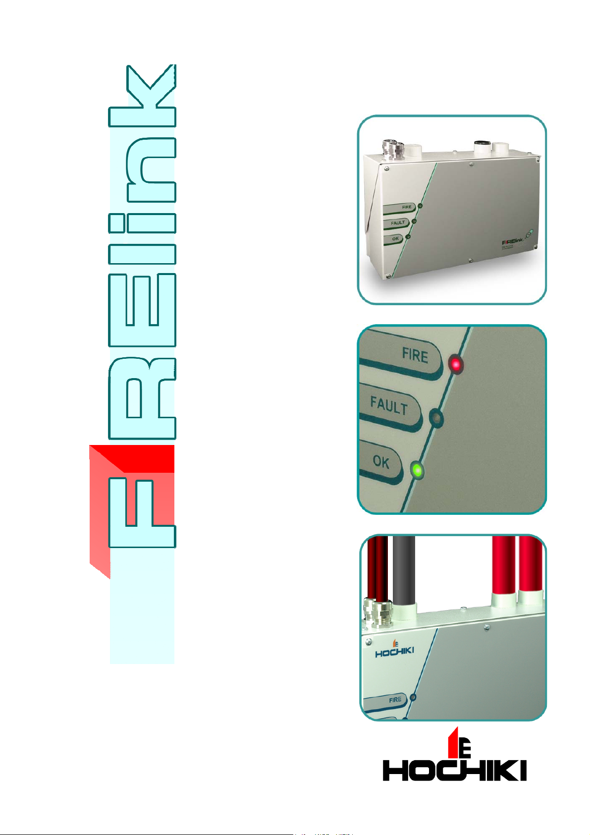
FIRElink-100 Air Sampling System
INSTALLATION MANUAL
Page 2

Page 2 of 40 FIRElink-100 – Installation Manual
This manual details the installation of:
FIRElink-100 Ai r S am pling Detector
If you have any queri es regarding this product or its functionality please cont ac t:
Hochiki Europe (UK ) Limited
Grosvenor Road
Gillingham Business Park
Gillingham
Kent ME8 0SA
Tel: +44 (0) 1634 260133
Fax: +44 (0) 1634 260132
Web: http://www.hochikieurope.com
Email: psupport@hochikieurope.com
©2010 Hochiki Europe (UK ) Ltd. All rights reserved. No part of this docum ent may be reproduc ed,
stored in a retri ev al system, or transmitted, in any form or by any means, without the prior permission i n
writing of Hochiki Europe (UK) Ltd.
Hochiki Europe ( UK ) Limit ed r eserves the right to alter the specifications of its products from time to time
without notice. Although every effort has been made to ensure the accuracy of the information contained
in this document it is not warranted or represented by Hochik i E ur ope ( U K ) Limit ed to be a complete and
up-to-date description.
Document Detail s:
Title: FIRElink-100 Ai r S am pling Detector - Installation Manual
Issue 4.0
Issue Date October 2010
Part No. 9-5-0-345
© 2010 Hochiki Europe (UK) Lt d
9-5-0-345/ISS4/OCT10
Page 3

FIRElink-100 – Installation Manual Page 3 of 40
Table of Contents
1 Introduction.................................................................................................................................... 5
1.1 Indicators............................................................................................................................... 6
1.2 Inside the Detector................................................................................................................. 7
1.3 Detector Terminal Block Connections..................................................................................... 8
1.4 Prog ramming th e Dete c to r......................................................................................................9
1.5 Time and Date Tab................................................................................................................. 9
1.6 Alarm Levels and Delays Tab............................................................................................... 10
1.6.1 Alarm Levels - (Level subgroup)....................................................................................... 10
1.6.2 Alarm Delays - (Delay subgroup)...................................................................................... 10
1.6.3 ClassiFire® Override ........................................................................................................ 10
1.6.4 Alarm Factor....................................................................................................................10
1.6.5 LDD Enable ..................................................................................................................... 11
1.6.6 FastLearn Enable............................................................................................................. 11
1.6.7 Auto FastLearn Enable..................................................................................................... 11
1.6.8 ClassiFire 3D...................................................................................................................11
1.6.9 Demo M o d e..................................................................................................................... 11
1.7 Day/Night Switching Tab...................................................................................................... 12
1.7.1 Day Start / Night Start –.................................................................................................... 12
1.7.2 Disable Day / Night Switching........................................................................................... 12
1.8 Alarm Actions Tab................................................................................................................ 12
1.8.1 Remote Functions (Remote Input subgroup) .................................................................... 12
1.8.2 Programmed Isolate......................................................................................................... 12
1.8.3 Latching Alarms............................................................................................................... 12
1.8.4 Latching Faults.................................................................................................................12
1.8.5 Cascading Alarms............................................................................................................ 12
1.9 De vice Information Tab........................................................................................................ 13
1.9.1 Device Type.....................................................................................................................13
1.9.2 Firmware Version............................................................................................................. 13
1.9.3 Run-time Hours................................................................................................................ 13
1.9.4 Watchdog Count .............................................................................................................. 13
1.9.5 Device Text...................................................................................................................... 13
1.10 Referencing Tab...................................................................................................................13
1.10.1 Reference Detector.......................................................................................................... 13
1.10.2 Reference Enable............................................................................................................ 13
1.10.3 Reference Level............................................................................................................... 13
1.10.4 Reference Back-off.......................................................................................................... 13
1.11 Flow Monitoring Tab.............................................................................................................14
1.11.1 Flow Rate......................................................................................................................... 14
1.11.2 Flow High Limit ................................................................................................................ 14
1.11.3 Flow Low Limit................................................................................................................. 14
1.11.4 Flow Fault Delay.............................................................................................................. 14
1.12 Miscellaneous Tab ............................................................................................................... 14
1.12.1 Access Code .................................................................................................................... 14
1.12.2 Chart Recording Rate....................................................................................................... 15
1.12.3 Separator Condi tion ......................................................................................................... 15
1.12.4 Separator Change Date.................................................................................................... 15
1.12.5 Factory Default.................................................................................................................16
1.13 Other Remote Software Features......................................................................................... 16
1.13.1 Reset............................................................................................................................... 16
1.13.2 Histogram Screen............................................................................................................ 16
1.14 Chart Recording................................................................................................................... 18
1.15 Load / Save Function Settings.............................................................................................. 18
2 Design Limitations....................................................................................................................... 20
2.1 System Design..................................................................................................................... 21
2.2 EN54-20 Compliance........................................................................................................... 22
3 Installation.................................................................................................................................... 24
3.1 Docking Station.................................................................................................................... 24
© 2010 Hochiki Europe (UK) Lt d
9-5-0-345/ISS4/OCT10
Page 4

Page 4 of 40 FIRElink-100 – Installation Manual
Mechanical Installation......................................................................................................25
3.1.1
3.1.2 Elect r ical Insta l la t io n.........................................................................................................25
3.1.3 Power Supply Connections ...............................................................................................25
3.1.4 Signal Connections...........................................................................................................25
3.2 Fina l installation....................................................................................................................26
4 Interfacing.....................................................................................................................................28
4.1 Setting the Detector Address.................................................................................................28
4.2 Connecting a FIRElink-100 to a SenseNET/RS485 Detector Network....................................29
4.3 Connecting a FIRElink-100 to an addressable Fire Panel ......................................................30
4.4 Connecting to a PC...............................................................................................................31
5 Event Lo g......................................................................................................................................32
6 Commissioning.............................................................................................................................34
6.1 Commissioning Checklist ......................................................................................................34
7 Maintenance..................................................................................................................................35
7.1 Diagnostics...........................................................................................................................35
8 Troubleshooting ...........................................................................................................................37
8.1 Nuisance Alarms Occur Too Often........................................................................................37
8.2 Elevated Smoke Levels Do Not Gener ate Alarms..................................................................37
8.3 Low Mean Output..................................................................................................................37
8.4 Detector Sensitivity Varies Over Time ...................................................................................37
8.5 Flow Fault Errors...................................................................................................................37
8.5.1 "Low Flow" Error Messages. ............................................................................................. 38
8.5.2 "High Flow" Error M e ssage s..............................................................................................38
9 Do's and Don'ts.............................................................................................................................39
10 FIRElink-100 Specification........................................................................................................40
© 2010 Hochiki Europe (UK) Lt d
9-5-0-345/ISS4/OCT10
Page 5
FIRElink-100 – Installation Manual Page 5 of 40
1 Introduction
FIRElink-100 is a highly sophisticated ‘nex t generation‘ of High Sensitiv ity Aspirating Smoke Detection
product that has been designed t o ensure t hat installation and com m issioning is as simpl e as possible,
while optimising performance.
FIRElink-100 incorporates a patent ed ‘ar tif ic ial intelligence‘
known as ClassiFire ®, which allows the detector t o configur e
itself to optimum sensitivity, alarm thr eshol ds and minimum
nuisance alarms for any environment. ClassiFire intelligence
0832
Hochiki Europe (UK ) Limited
Grosvenor Road
Gillingham Business Park
Gillingham
Kent ME8 0SA, UK
09
0832-CPD-1195
EN54-20: 2006
Aspirati ng smoke detectors
for fire det ection and fire alarm
systems for buildings
CLASS A, B and C
also monitor s the detector chamber and dust separator for
contamination, continually adjusting the appropri ate operating
parameter s to counter ac t the negative effects of such
contamination.
The FIRElink range of detectors is unique in being able to
provide a consistent level of protection in a v er y wide range
of environments by continuously making minor adjustments
to sensitivity. The FIRElink range of detector s has proven its
worth many tim es by detecti ng ‘difficult-to-detect‘ slow growth
electric al ov erl oad incipient fires in ‘dif ficult‘ environments.
This handbook gives information likely to be needed f or most
installations, but for more detailed information on subjects
such as Fresh Air Ref er enci ng, please refer to the complet e
Technical M anual or System Desi gn Guide.
This equipment is Class 111 as defined in EN60950 (i.e., this
equipment is designed to oper ate from Safety Extra Low
Voltages and does not generate any haz ar dous voltages).
Technical data: see INF48027 held
by the manufacturer
NOTE: If this equi pm ent is part of a fire detection system, i t should be suppl ied from an approved power
supply conf orming to EN54-4.
This symbol appears on the m ain boar d of the unit and indicates that the board
contains static sensitive component s. S uitable anti-static pr ec autions must be
taken when handling t he boar d.
This label is loc ated on the laser chamber and signifi es that the unit is a Class 1
LASER CLASS 1
PRODUCT
Laser product as specif ied in IEC 60825-1. The unit incorporat es a Cl ass 3B
embedded laser t hat must not be removed from the detector as ret inal damage
may result if the laser beam enters the eye.
This symbol appears on the m ain boar d of the unit and indicates that the board
contains static sensitive component s. S uitable anti-static pr ec autions must be
taken when handling t he boar d.
© 2010 Hochiki Europe (UK) Lt d
9-5-0-345/ISS4/OCT10
Page 6
Page 6 of 40 FIRElink-100 – Installation Manual
Hochiki Europe has tak en ev er y c ar e to ensure that FIRElink-100 i s as simpl e to install as possible but in
case of diffi c ulty, please contact our Product Support Department to ensure trouble f r ee inst allation and
operation. Hochiki Europe takes no responsibility for damage or injury occ asi oned as a resul t of failing to
install or oper ate the equipment in accordance with these instructions.
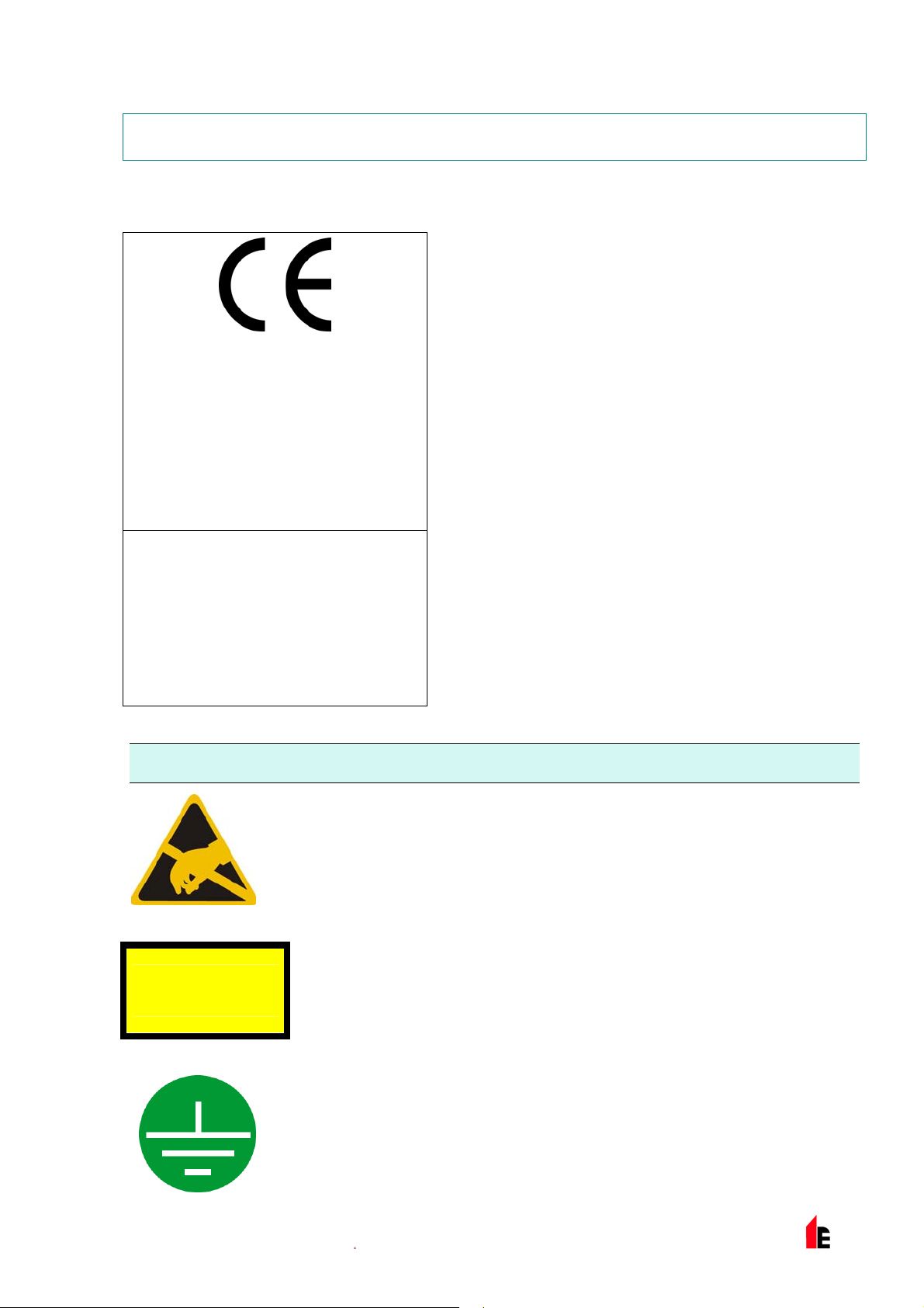
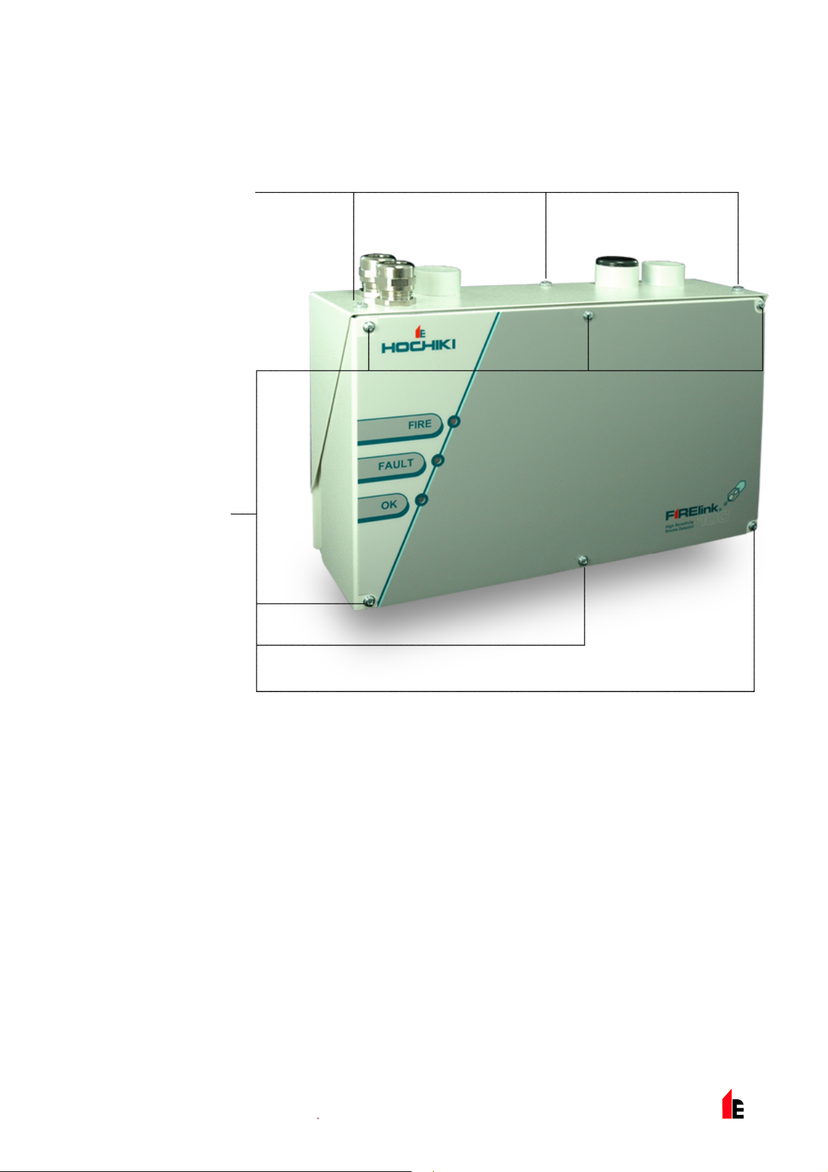
1.1 Indicators
OK. Illuminates to show
normal operati on when
there are no fault s. The
OK lamp will flash during
the 15 minute
Fastlearn™ peri od when
the detector is first
learning about its
environment.
© 2010 Hochiki Europe (UK) Lt d
Fault. Illuminates
when the unit has a
fault and a fault
signal is bei ng sent
to the fire alarm
panel.
Fire. Illuminates when the alarm level has been
reached and the appropriate time delays hav e
expired.
9-5-0-345/ISS4/OCT10
Page 7

FIRElink-100 – Installation Manual Page 7 of 40
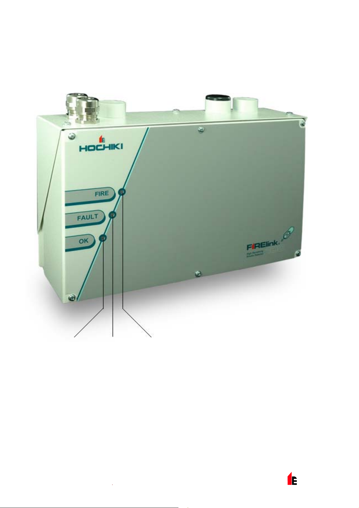
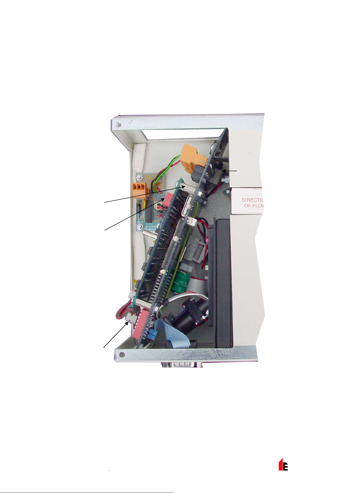
1.2 In si de the Detector
Fan Relay Board Removable Terminal
Blocks
Filter
Detector Addr ess
DIP Switch
RS232 Serial Port Addressable Program mable
Interface Card (FIRElink-APIC)
port
© 2010 Hochiki Europe (UK) Lt d
9-5-0-345/ISS4/OCT10
Page 8
Page 8 of 40 FIRElink-100 – Installation Manual
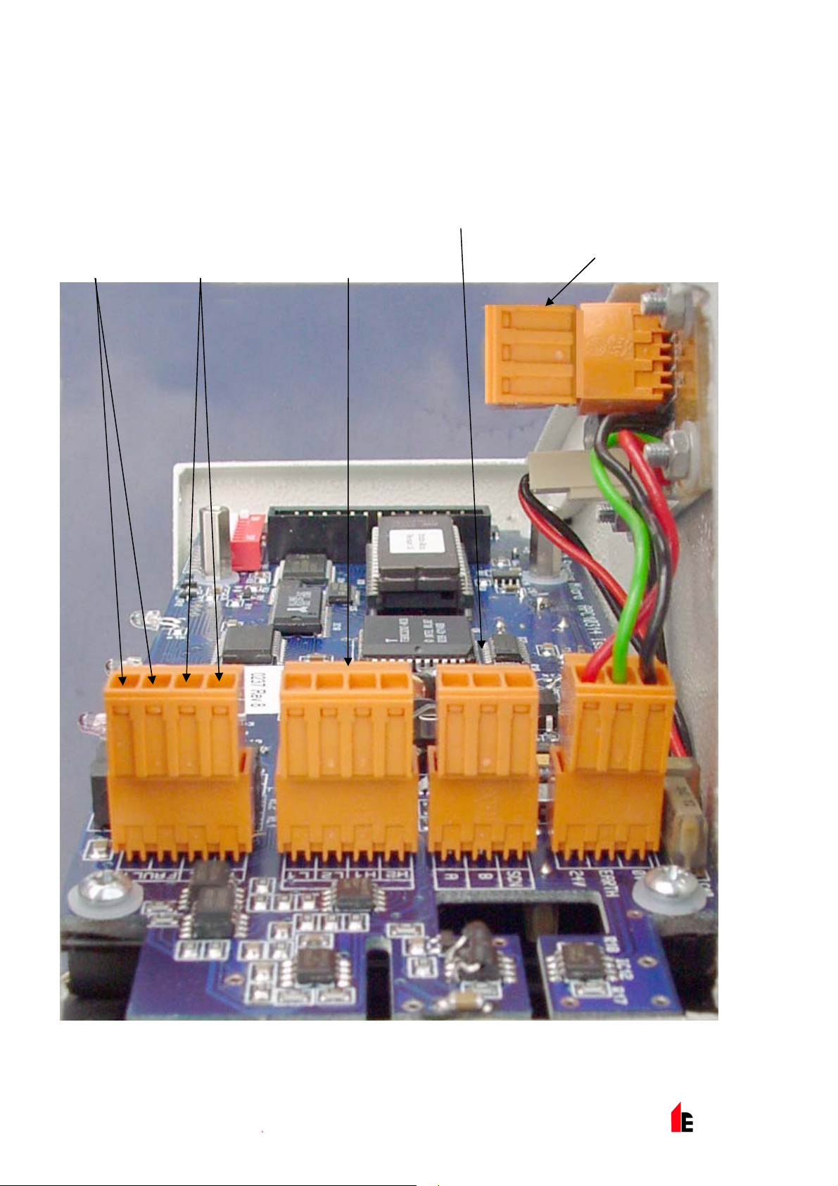
1.3 Detector Terminal Block Connections
Normally
closed FAULT
relay cont acts
Normally open
FIRE relay
contacts
FIRElink-APIC
addressable bus
connections for use i n
conjunction with
interface card (see
sections 3.1.4 and 4. 3)
RS485 / SenseNET
connections (see
sections 3.1.4and 4. 2)
Power supply
connections (see
section 3.1. 3)
© 2010 Hochiki Europe (UK) Lt d
9-5-0-345/ISS4/OCT10
Page 9
FIRElink-100 – Installation Manual Page 9 of 40
1.4 Programming the Detector
The FIRElink - 100 m ay be programmed from a PC when connected to the detector via a standard 9-pin
serial lead connected to the serial port of the computer and the 9 way socket at the base of the detector
(see section 4. 4 “ Connec ting to a PC” page 31). In order to do this, it is necessary to install the remote
control software onto the computer. A copy of the remote control software is contained on a floppy disk
supplied with each detector. Install the sof tware in accordance with the on-screen i nstr uc tions. To open
the software , select St art > Programs > Hochiki > Remote 3.0
Access the drop-down list to the right hand side of the toolbar. This defaults to “Detect or 001”. Scr oll
down this list t o select the det ec tor number corresponding to the connected detector’s address number if
the address is other t hen the factory default setti ng of 1 (see section “Setting the Det ec tor Address” on
page 28).
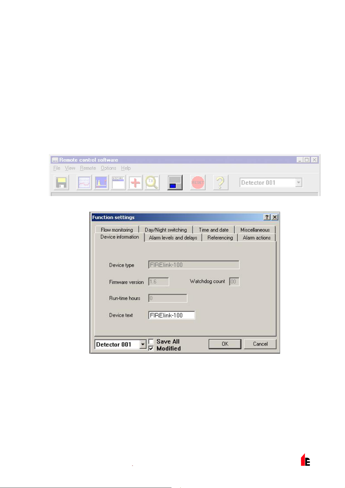
The programmable functions are all accessed though the Options > Detector settings submenu or by
clicking on t he detector button on remote software toolbar as i ndicated below:
The following screen is displayed:
This window contains all the programmabl e functions for the FIRElink-100. To amend one of t he
programmable functions, go to the relevant tab, make the change and then click OK. This will save the
change to the detec tor’s internal firmware.
A list and explanation of the various functions is given below, with the functi ons grouped by the tab under
which they appear.
1.5 Time and Date Tab
It is important that the time and date be set up correctly on the controller’s internal cal endar /clock
because it uses this inf ormation to store events in the event log. See section 5 “Event Log” on page 32
for more details. Unless speci ally ordered, units are supplied with the correct setting for UK time. This is
© 2010 Hochiki Europe (UK) Lt d
9-5-0-345/ISS4/OCT10
Page 10

Page 10 of 40 FIRElink-100 – Installation Manual
backed up with a rechargeable battery. Later adjustm ents to the clock setti ng shoul d not exceed ± 70
minutes unless a FastLearn is initiated.
1.6 Alarm Levels and Delays Tab
1.6.1 Alarm Levels - (Level subgroup)
The value set in the Fir e, Pr e- Al arm and A ux functions in the Level subgroup is the rel atively scaled
bargraph level at which the appropriate alarm is initiated on the detector. The Fire 2 level assigns an
absolutely scaled alarm level in % obs/m.
The Aux level is set by factory default at level 10 which means that this alarm will occur after the Fi r e
alarm. The def ault level settings for Pre-Alarm and Fire 1 are 6 and 8 respectively. The def aul t sett ing for
Fire 2 is 20% obs/m.
1.6.2 Alarm Delays - (Delay subgroup)
The alarm delay i s the number of seconds that an alarm level has to be continuously sensed before the
alarm is initi ated. Each alarm level has a programmable delay of between 0 and 90 seconds. The default
delay for each al arm level is 5 seconds.
1.6.3 ClassiFire® Override
This functi on has no curr ent use on the FIRElink-100 but is reserved for future expansion purposes.
1.6.4 Alarm Factor
The detector sensitivity is set with this entr y , which will also affect the probability of nuisance alarms. 0 =
high sensitiv ity, higher probabili ty , 8 = low sensitivity, lower probability. The default alarm factor is 4.
Note: The highest sensitivity setting is suit able for clean, environm entally controlled envir onm ents, for
example semic onduc tor manufacturing clean r oom s where airborne pollut ants are kept to an
absolute minim um and the least contamination is cause for alarm.
Use of this setti ng in a busy mac hine shop would lead to relatively frequent nuisance alarm s due
to the normal vari ation of atmospheric contamination and a lower sensitivity setting is
recommended. I t is theref ore important that the alarm fact or chosen is suitable for the area
to be protected. When the appropriate alarm factor for the protected ar ea has been set, nuisance
alarms will be reduc ed to an absolute minimum.
The following table gives suggested settings of ClassiFire alarm setting for different locations:
Alarm
Factor
0 Extremely High Once per year Semiconductor manufacturing clean room
1 Once per 5 years Computer room
Sensitivity
Probability of
Nuisance Alarm
Suggested Protected Area
2 Once per 10 years Non- smoking office
3 Once per 50 years Clean factory
4 Medium Once per 1000 years Warehouse
5 Medium Once per 5000 years Warehouse with diesel trucks operati ng
6 Medium Once per 10000 years Warehouse with diesel trucks operati ng
7 Low Once per 20000 years Warehouse with diesel trucks operati ng
8 Low Once per 100000 years Warehouse with diesel trucks operati ng
© 2010 Hochiki Europe (UK) Lt d
9-5-0-345/ISS4/OCT10
Page 11

FIRElink-100 – Installation Manual Page 11 of 40
1.6.5 LDD Enable
When this function is ticked, Laser Dust Discrimination (LDD™) increases the respon se time of the
detector slightly, whilst greatly r educi ng the likelihood of nuisance alarms due to dust ingress. LDD may
be disabled in v ery clean r oom s for a slightly faster response to sm ok e by setting this function to unti c ki ng
the box. This function is enabl ed by default.
NOTE: Disabli ng LDD is not r ec ommended f or ar eas other t han m anufacturing clean rooms, due to the
increased probability of nuisance al arms in most other operating envi r onm ents.
1.6.6 FastLearn Enable
If the detect or i s in FastLearn mode, unticking this box will stop the FastLearn process. Using the
function in this way is neither recommended nor supported by Hochiki Europe (UK) Limited).
Ticking the box will star t a FastLearn at any time. The green “OK ” LED on t he front of the det ec tor will
flash for the fift een mi nutes that it takes for the FastLear n pr ocess, and will then change to constant
illumination to indicate that the FastLearn is complete.
Note: It will tak e a further 24 hours after the FastLearn for full sensit ivity to be reached, unless
Demonstration Mode has been initiated (see secti on 1.6. 9 “ Dem o M ode” on page 11) . It is
essential for proper functioning that the detector not be left in Demonstrat ion mode, and that it be
allowed to complete the 24-hour learning period. To cancel demo mode, tick this box or power
down and restart the det ec tor to initiate FastLearn mode.
1.6.7 Auto FastLearn Enable
When enabled, this function ensures that if the detector is powered off for any reason (for maintenance or
to be moved to a new area for example), a FastLearn is commenced aut om atically on power-up.
There may be occasions when it is desir able to power down the detect or for short periods of time, and it
is highly likely that ambient contaminant levels will be the same on power-up. Under t hese circumstances
it may not be desirabl e that the det ec tor should to go through the whole lear ning process again. To this
end, this function can be unticked before power-down, where upon it will retur n to the original settings on
power-up. This function is enabled by default.
1.6.8 ClassiFire 3D
If this function is ticked, then the detect or will ignor e any pr e- set time delays in the event of an
unacceptably r apid increase in smoke densit y, thereby mi nimi sing response time to 'rapid growth' fires.
This functi on would normally only be used where there were long t ime delays programmed on t he alarm
levels. This function is disabled by default.
1.6.9 Demo Mode
Demonstration mode is an operating mode whereby the normal 24-hour learni ng period is bypassed, so
that the detect or can reach high sensitivity aft er only the 15 minute FastLearn period. This can be used so
that initial smoke testing and other commissioning can be carried out.
However, it must be understood that, since the alarm levels will be based solely upon the
sparse data gathered during the FastLearn period, there is a risk of nuisance alarms due
to normal variations in ambient smoke levels. For this reason, the detector should not be
left in Demo mode for normal use when connected to a fire panel.
© 2010 Hochiki Europe (UK) Lt d
9-5-0-345/ISS4/OCT10
Page 12

Page 12 of 40 FIRElink-100 – Installation Manual
1.7 Day/Night Switching Tab
1.7.1 Day Start / Night Start –
These values are t he times to the nearest hour at which the day/ night switching is desired to take place
on the detector . Entries are made in 24-hour format, f or example 19 for 7pm. Day and night switching is
intended so that t he detec tor may automatically sel ect a diff er ent sensitivity when the protected area is
unoccupied and fewer cont am inants are being produc ed. ClassiFire automatically detects the change in
smoke level after the protected area is left, and if the time at which this happens is withi n + 70 mi nutes of
the programmed switchover time it selects the night-time histogram. This means that changes in time
setting, for example changing to summer tim e, may be ignored as the detector will take this into account.
The default times for day and night start are 08:00 and 19:00 respectively.
NOTE: That if the envir onm ent actually becomes more contami nated during the night period f or any
reason then ClassiF ire will adapt to that too, reducing the night-time sensitivity.
1.7.2 Disable Day / Night Switching
If day/night switching is not desirable, the Disable day/night switching box may be ticked to leave the
detector perm anently in day mode.
1.8 Alarm Actions Tab
1.8.1 Remote Functions (Remote Input subgroup)
These functi ons have no current use on the FIRElink-100 but are r eserved for future expansion purpose s.
1.8.2 Programmed Isolate
When this function is ticked the controller will not generate alarms and will not indicate a fault conditi on on
any fire panel whic h is connected, for use during detec tor m aintenance for example. The “Fault” light will
be illuminated on the detector front panel. The isolated condition will be disabled automatic ally aft er 7
days if not manually disabl ed. This function is disabl ed by default.
1.8.3 Latching Alarms
When this function box is tic k ed it requires a reset from the controlling computer to clear an al arm
condition. If untic k ed, the alarm signal is extinguished as soon as the alarm condition ends. This is the
factory default setting.
1.8.4 Latching Faults
When this function box is tic k ed it requires a reset from the controlling computer to clear a fault condition.
If untick ed, t he fault si gnal is extinguished as soon as the faul t condition ends. This is the factory default
setting.
1.8.5 Cascading Alarms
Ticking this function box means that only when the detector ’s cont r oller has gone into Pr e-Alarm does the
controller star t counting down the main Fire delay , in other words t he time delays on Pre-Alarm and Fire 1
are cumulative. The Aux alarm is not included in the cumulativ e delay since it may be set to a higher
level than eit her the Pr e- Al arm or Fir e 1 lev els. This function is enabled by def ault.
© 2010 Hochiki Europe (UK) Lt d
9-5-0-345/ISS4/OCT10
Page 13

FIRElink-100 – Installation Manual Page 13 of 40
1.9 Device Information Tab
1.9.1 Device Type
This functi on is for displ ay pur poses only. It shows any special desi gnation for the unit, whic h will
normally be FIREli nk - 100.
1.9.2 Firmware Version
This functi on is for displ ay pur poses only . It shows the version number of t he fitted firmware chip.
1.9.3 Run-time Hours
This functi on is for displ ay pur poses only . It shows the cumulativ e tot al num ber of hours that the device
has run (this is not t he time that has el apsed sinc e last power-up, but the sum t otal of r un time si nc e the
detector memory was last reset).
1.9.4 Watchdog Count
The watchdog is a circuit built into the controll er t hat restarts the c ontroller in the event of a f ailur e to
function properly. This could be as a result of electri c al spi kes. This count shows the number of
interruptions found. The details of each problem can be found in the event log. See section 5, “Event
Log” on page 32for further details.
1.9.5 Device Text
This functi on has no curr ent use on the FIRElink-100 but is reserved for future expansion purposes.
1.10 Referencing Tab
1.10.1 Reference Detector
A FIRElink detector may use another detector as a fresh air refer ence. This function is the address of the
detector, whic h will be used as the reference. To set a detector as a ref er enc e detector, enter its address
as set by its inter nal DIP switc h i nto this function. This function is disabled by default.
1.10.2 Reference Enable
Ticking this box enables the reference for the det ect or , if one has previously been alloc ated in Reference
detector (see section 1.10.1). This function is disabled by default.
1.10.3 Reference Level
The value set wit h this function is the percentage ref er ence signal subtracted fr om the detector’s signal, if
a reference device has been allocated. The default value is 0.
1.10.4 Reference Back-off
This value is the delay time between a build up of pollution bei ng seen by t he r eference (if used) and the
pollution bei ng seen by t he detector. The default v alue is 15.
© 2010 Hochiki Europe (UK) Lt d
9-5-0-345/ISS4/OCT10
Page 14

Page 14 of 40 FIRElink-100 – Installation Manual
1.11 Flow Monitoring Tab
1.11.1 Flow Rate
This functi on is for displ ay pur poses only , and shows a value correspondi ng to the current airflow thr ough
the detector .
1.11.2 Flow High Limit
This value is the lev el abov e whic h airflow needs to increase to trigger a fault indication (which m ay
indicate a loose or damaged inlet pipe). Flow low limit and Flow high limit parameters are autom atically
set up on initial power-up.
1.11.3 Flow Low Limit
This value is the lev el below whic h airflow needs to be reduced to t ri gger a fault reading (which m ay
indicate a block ed pipe). Flow low limit and Flow high limit param eters are automatically set up on initial
power-up.
1.11.4 Flow Fault Delay
This featur e requi r es the Rem ote Control Software version 3.2 or later, available fr om the Hoc hiki E ur ope
Technical S uppor t Department (psupport@hochikieurope.com) .
The default flow fault thresholds on the FIRElink-100 are set to meet the stringent airflow monitoring
requirement s of E N54- 20, with a default flow fault delay of 30 seconds. This may lead to unwanted flow
faults bei ng gener ated when local conditions cause short-term variations i n airflow. To help alleviate such
issues, the flow fault delay is programm able from 30 to 240 seconds. T he flow level needs to be above
the high flow threshol d or below the low flow threshold throughout t he delay period for a fault to be
generated.
NOTE: When setti ng the value of this function, it is important to take into account that the contr ol unit (for
example, fire panel) may not react immediately to a trouble signal being generat ed by the
detector, and this will add to the total fault response tim e of the system.
The function v alue m ust be c hosen so that the total time between the detect or entering a fault condition
and a fault signal being gener ated by the panel meets the requirements of local or national fir e
regulations. The maximum allowable response time for EN54-20 compliance is 300 seconds, and that for
NFPA 72 compliance is 200 seconds.
As an example: in the latter case, if the flow fault delay were set to 180 seconds (within the limi t), but the
fire panel did not gener ate a fault indication for another 25 seconds, t he total response time of 205
seconds means the system would not comply with the regulat ions.
If documented figures are unavailable for the fire panel reaction time, compliance with reaction time
regulati ons may only be v erified by post-installation testing.
1.12 Miscellaneous Tab
1.12.1 Access Code
This is the access code required to amend programmable param eters. The default code is 0102. Once
the appropriate code is entered it may be changed here to any four digit number to limit unauthorised
access.
© 2010 Hochiki Europe (UK) Lt d
9-5-0-345/ISS4/OCT10
Page 15
FIRElink-100 – Installation Manual Page 15 of 40
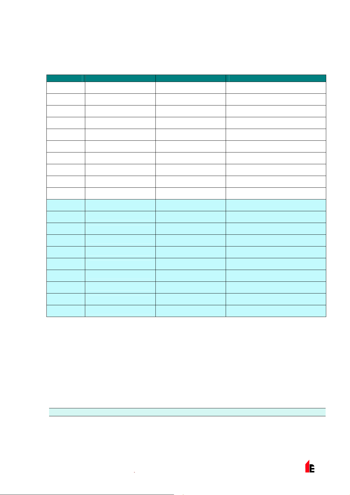
1.12.2 Chart Recording Rate
This functi on c ontrols how frequently the detec tor and alarm level or flow rates are stored in the FIRElink100’s internal c har t recorder log (see section 1.14, ‘Chart Recording’ on page 18).
Setting Type Storage Interval Time per Division on Chart Log
0 Detector Output 1 second 10 seconds
1
2
3
4
5
6
7
8
9
10 Flow Recording 1 second 10 seconds
11
12
13
14
15
Detecto r Ou tp u t
Detecto r Ou tp u t
Detecto r Ou tp u t
Detecto r Ou tp u t
Detecto r Ou tp u t
Detecto r Ou tp u t
Detecto r Ou tp u t
Detecto r Ou tp u t
Detecto r Ou tp u t
Flow Recording
Flow Recording
Flow Recording
Flow Recording
Flow Recording
5 seconds 50 seconds
12 seconds 2 minutes
30 seconds 5 minutes
1 minute 10 minutes
2 minutes 20 minutes
5 minutes 50 minutes
10 minutes 100 minutes
20 minutes 200 minutes
50 minutes 500 minutes
5 seconds 50 seconds
12 seconds 2 minutes
30 seconds 5 minutes
1 minute 10 minutes
2 minutes 20 minutes
16
17
18
19
In the above table the shaded cel ls indicate flow rat e r ecording whilst the white cells indicate detector and
alarm level recording.
At the slowest recording rate, one month of data can be recorded. The factory default setti ng is 8.
Flow Recording
Flow Recording
Flow Recording
Flow Recording
5 minutes 50 minutes
10 minutes 100 minutes
20 minutes 200 minutes
50 minutes 500 minutes
1.12.3 Separator Condition
The value given at t his func tion is the efficiency rati ng of t he dust separator element in the det ector as a
percentage of t he eff ic iency of a clean separator. A new element will give a reading of 99 in this function.
When the efficiency has decreased to 80%, the Fault indicator LED will illumi nate and t he ev ent log will
show “Separator rene w”.
NOTE: Fitting a new elem ent will reset this figure to 99
1.12.4 Separator Change Date
This function defaults to “--“, which means that a separator fault will only appear when the efficiency
decreases to 80% (see 1.12.3, “ S epar ator Condition” ). Howev er , a dat e may be entered into this function
© 2010 Hochiki Europe (UK) Lt d
9-5-0-345/ISS4/OCT10
Page 16

Page 16 of 40 FIRElink-100 – Installation Manual
to allow for a scheduled m aintenance period. The detector will then generate a separator f ault at the
planned tim e regardless of the condition of the separator , although degradati on of the separator to below
80% effici enc y befor e this date will override this (see section 7, “Maintenance” on page 35 for further
details.
1.12.5 Factory Default
Enabling this function will reset each programmable function to the default value indicated in the text,
where a default setting is specified. It will also put the detector into FastLearn mode, regardless of
whether or not Auto F astlear n is enabled (see section 1.6.7 “ A uto F astLearn Enable” on page 11). This
ensures that the fl ow setups and al ar m thresholds are optimi sed to the detector’s working envi r onment
after resetti ng. It should be noted that where a ClassiFire alarm factor other than the default is required
for the protect ed ar ea, t his wil l need to be re-entered. Section 1.6.4 gives details of the Cl assiF ire alarm
factors.
1.13 Other Remote Software Features
1.13.1 Reset
If latching alarms (see section 1.8.3) or l atching faults (see section 1.8.4) are enabled, the relevant alarm
or fault warnings will remain on the detector front panel LEDs and controlling unit unti l a r eset is
performed. If using SenseNET software, indivi dual detectors can be reset (refer t o the S enseNET User
Guide for details). In the remote software, a global r eset is available which resets all detectors on the
SenseNET loop, or a singl e stand- alone detector.
To perform a reset, either select the menu options Options > Global Reset or click the button on the
toolbar as indic ated below:
1.13.2 Histogram Screen
The histogram screen sho ws various aspects of the detect or function. To enter the histogram screen,
either selec t t he m enu options View > Histogram Viewer, or click the but ton on the toolbar as indicated
below:
The following screen is displayed:
© 2010 Hochiki Europe (UK) Lt d
9-5-0-345/ISS4/OCT10
Page 17

FIRElink-100 – Installation Manual Page 17 of 40
Smoke Density histogr am Alarm flags
There are two types of sm ok e density hi stogr am ; one shown in blue (the “fast” histogram) which updates
every 15 minutes, f eeding information to the long-term “slow” histogram s (which appear in yellow). These
set the detector sensit ivity based on the ambient sm oke conditions and it takes 24 hours f or the two slow
histogram s (t he “ day ” and the “ night” histograms) to compl ete their learning phase (see section 1.6.6).
Detector sensitivity is based on the fast histogram during FastLearn and is ther eafter based on the
currentl y active slow histogram. However, although the positions of the al arm fl ags are based on the sl ow
histogram, sudden changes in smoke density are pic k ed up by the fast histogram so that early warning i s
given.
Sensitivity: The current absolute sensitivity of the detector in perc entage obscuration per m etre ( %
obs/m)
Mean: The current mean value of smoke density, taken from the currently “active” hist ogr am and given
as a percentage of full scale deflection.
Variance: The “spread” of data in the currently “activ e” histogram and given as a percentage of full scale
deflecti on.
FastLearn: If the detector is currently in FastLearn mode, this will show the number of minutes
remaini ng in the FastLearn period. When thi s period has elapsed i t will read “OFF”.
Alarm factor: This is the ClassiFire alarm factor (see section 1.6. 4 “Alarm Factor” on page 10)
Day/night: This indi c ates the cur r ently active slow histogram
Alarm leve ls: These fi gur es give the position of the various alarm flags in terms of a percentage of full
scale deflec tion.
Detector output: This shows the real-t im e variation in background smoke levels in terms of a
percentage of f ull scale deflection.
© 2010 Hochiki Europe (UK) Lt d
9-5-0-345/ISS4/OCT10
Page 18
Page 18 of 40 FIRElink-100 – Installation Manual
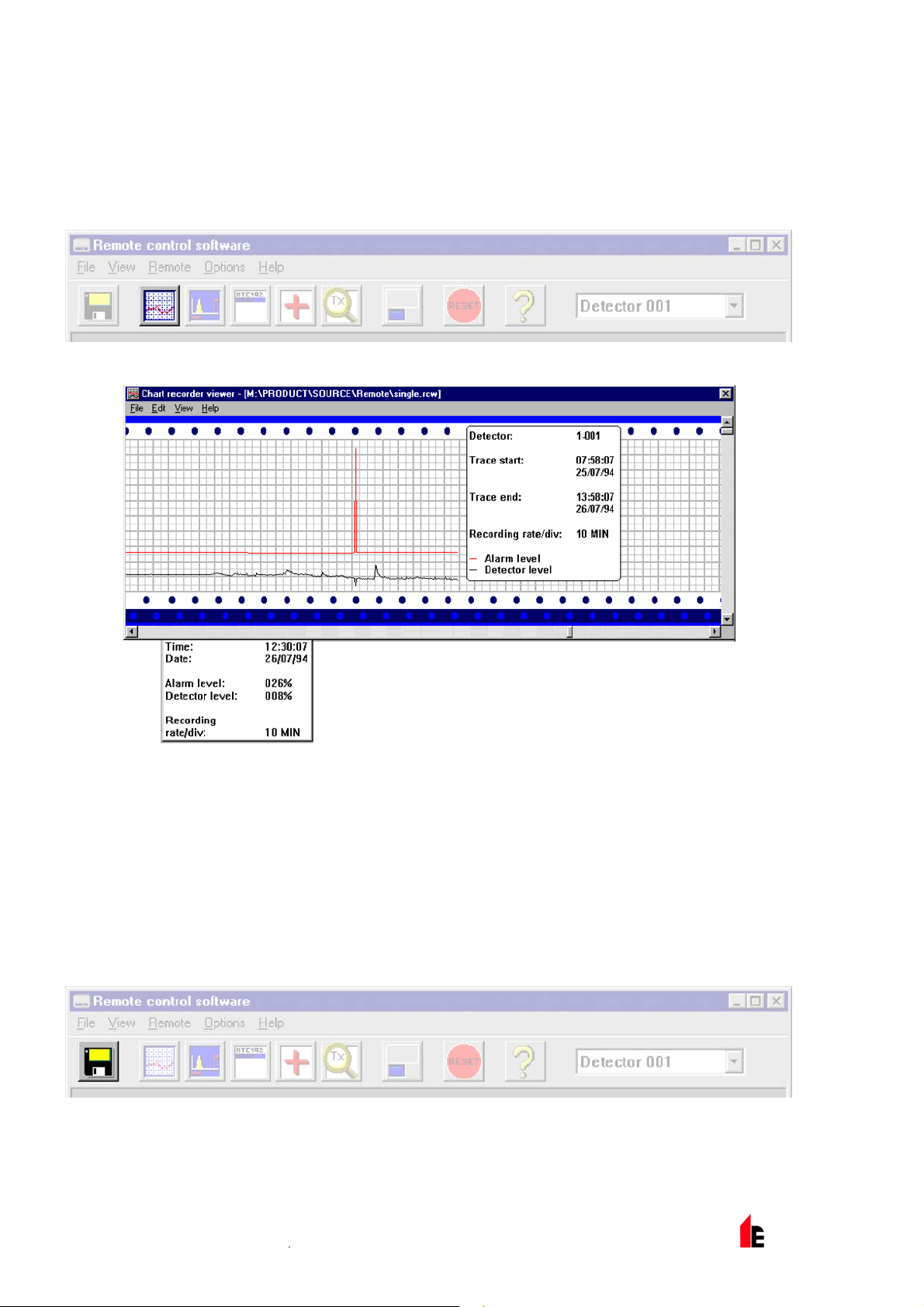
1.14 Chart Recording
The chart recording function shows how smoke densit y i n the protected area has varied over time. The
chart may be downloaded to di sk or pr inted out from a connected print er.
To access the chart log, sel ec t t he m enu options View > Chart Recording or click t he butt on on the
toolbar as indic ated below:
The following screen is displayed:
The red trace is the current alarm level and the black trace is the detector output. By movi ng the c ur sor
along the chart, the “Char t information” window (shown at t he bott om left) updates to show the date and
time, detector lev el and alarm level of the relevant period. The File menu option in the chart recording
window allows the chart r ec or ding to be saved to disk or printed to a connected printer, and allows a
previously saved chart recording to be loaded. Chart recording files hav e the extension “.rcw”.
1.15 Load / Save Function Settings
Where a custom set of programm able function settings is commonly used, these may conveni ently be
saved to or loaded fr om di sk. To open a detector function settings (.dfs) file, select the m enu options File
> Open or click on the button on the toolbar as indicated below:
A file browser window will be displayed, click on the “List files of type” drop-down box and select “Detector
settings (*.dfs)” as indicated below:
© 2010 Hochiki Europe (UK) Lt d
9-5-0-345/ISS4/OCT10
Page 19

FIRElink-100 – Installation Manual Page 19 of 40
A list will appear of all detector settings files stored on t he c ur r ent drive. As a special case, if desiri ng to
recall the factory default settings, ther e is a fi le named ‘default. dfs’ in the ‘remote2k’ director y . Loading
this file will reset the detector to the factory default.
© 2010 Hochiki Europe (UK) Lt d
9-5-0-345/ISS4/OCT10
Page 20
Page 20 of 40 FIRElink-100 – Installation Manual
2 Design Limitations
FIRElink-100 is intended to provide LOCALIS E D inci pient fire detection only. Thi s
means that it is suitable for the substantial range of applications typified by; small
non-compartmentalised rooms, warehouse rac k ing, or pieces of electronic or
electrom ec hanic al equipment where it is desirabl e to achieve individual incipient fire
reporting. In compartmentalised room s, eac h c om partm ent would nor mally use
individual FIRElink-100 detector s.
This product em ploy s a very low-power aspirator and the aspirating capability of the FIREli nk - 100
detector is limi ted accordingly. FIREli nk-100 is NOT intended to protect lar ge areas, or to sample from
areas where there may be any difference in airflow rates or pressure differenti als. Application of
FIRElink-100 in these circumstances is not r ec ommended. If detection in environments conforming to
these descript ions is required, alternative versions of FIRElink pr oduc ts should be used.
Maximum length of sampling pipe used with the FIRElink-100 detector is 100 metres in ST ILL AIR with 20
sampling holes (or Capillary Remote Sampling Points). This will provide a transport time from the end of
the sampling pipe within 120 seconds. If the protected area has airflow present, t he m aximum permitted
sampling pipe l ength will be reduced. In areas or applications where the airflow rate exc eeds 1 metre per
second, maximum sampling pipe length is reduced t o 50 metr es.
Sampling pipes must have capped ends. The end cap should be drilled with a hole normally bet ween 4
or 5mm diameter and free from bur rs. Sampling holes should normally be 3-4mm diameter or as
calculated by Pi peCA D, and f r ee from burrs. Each pipe run should not have more than 10 holes
(including the end cap hole). Pipe transit time from the furthest sampling hole from the detector must not
exceed 120 seconds and an approved type of pipe must be used for installations conforming to LPCB
requirement s. It is strongly recommended that the sm oke transit time from the furthest sam pling hole be
checked during c ommissioning tests. Capillar y Remote Sampling Points may be used in place of
sampling holes.
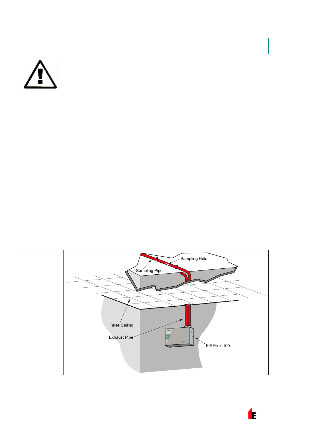
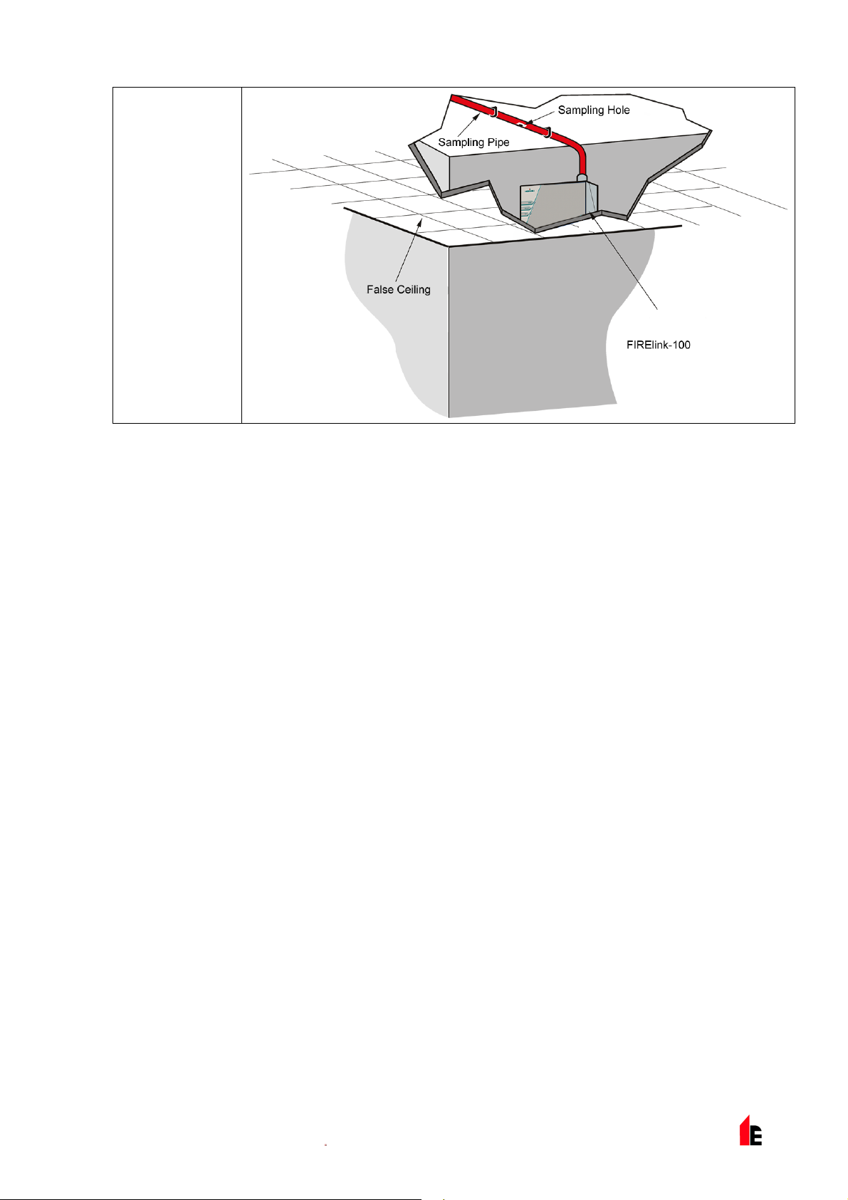
FIRElink-100 is supplied with a ‘Piped Exhaust’ type Docking Station (see illustration A). This is prim aril y
intended to allow the F IRElink-100 detect or to sample from areas that may be at a different air pressure
to the detector loc ation. Typical uses are for air-duct sampling and allowing t he installation of the detec tor
in under-floor or ceili ng v oids or when sampling from pieces of c om puter related equipment.
A
Above Ceiling
Sampling
with exposed
detector.
© 2010 Hochiki Europe (UK) Lt d
9-5-0-345/ISS4/OCT10
Page 21
FIRElink-100 – Installation Manual Page 21 of 40
B
Above Ceiling
Samp ling wi th
detector
mounted in
ceilin g void.
2.1 System Design
Simple designs with short sampling pipes produce the best results. Complex sampli ng pipe runs should
be avoided with the FIRElink-100 detector. The use of ‘T’ branc h- pipes is not recommended. To assist in
design and to verify system performance, it is advi sabl e to use the FIREl ink PipeCAD® sampling pipe
modelling software.
Always locate t he sampling points in positions to whic h smoke m ay reasonably be expected to travel. Do
not expect ceiling mounted sampling point s to oper ate satisfactorily if air fl ow from air-conditioni ng
systems keeps the cool smoke from an incipient fir e reaching from reaching ceili ng level. In this instance
it is usually better to locate the sampling pi pe dir ectly in the airflow (for exam ple ac ross the return air
register of an air condi tioning unit).
There is no substitute for carrying out smoke tests pri or t o installation of pipe work to indicate suitable
sampling point loc ation.
No more than TWO Air Handling Unit s may be pr otected with one FIRElink-100 detector. In this
applicati on, ensure t hat the sampling pipe is raised clear of high velocity air in the imm ediate vicinity of
the air intake grille on stand-off posts as shown below:
© 2010 Hochiki Europe (UK) Lt d
9-5-0-345/ISS4/OCT10
Page 22

Page 22 of 40 FIRElink-100 – Installation Manual
2.2 EN54-20 Compliance
The installation must be designed using PipeCAD soft ware, whic h is provided free on the CD shipped
with each detect or . Aft er designing the installati on inc luding pipes, endcaps and sampling holes, enter
the detector type in the “Type” drop-down list in “Options” “ Calculation options”.
Select “Options” “Calculate” or clic k on the c alc ulator icon. The software will pr om pt you to choose fr om
“Use set hole sizes” “B est flow balance” and “Max. permissible transit time”. Sel ect the appropr iate option
and click “OK”. The resul ts for each pipe (“View” “Results”) show calculations for each sampling hole on
the pipe with the nearest to the detector at the top of the screen, and t he endc ap hole at the bottom.
“Transit time” shows the smoke transit time to the detector from each sampling hole. For EN54-20, t his
must be below 120 seconds from ev er y hol e. The column headed “Hole sensitiv ity % obs/m” shows the
predicted sensit ivity for each hole. For the instal lation to comply with EN54-20, each sampling hole must
be no less sensitive than 0.62% obs/m.*
The calculation can be further refined by leaving a working detector in the protected area for at least
24hrs at the int ended alarm factor for the installation (this could be done befor e or after installation). The
detector sensitivity can be read from the “Sensi tivity” figure on the histogr am scr een of the Remote
software supplied with each detector. Enter this figure into the PipeCAD calculation under “Options”
“Calculation options”, “Detector sensitivity”. Clicking on “OK” will update the hole sensitivities to the figur e
expected for the actual layout.
Commissioning and per iodic system tests must inv olv e smok e tests to verify that the system performs as
expected and ent ers Fire 1 alarm within 120 seconds from the f arthest hole. The detector sensitiv ity must
also be inspected to ensure it has not radically f allen from the installed figur e. If it has changed for any
reason. the new fi gur e m ust be re-ent er ed into PipeCAD and the recalcul ated hole sensitivities must be
© 2010 Hochiki Europe (UK) Lt d
9-5-0-345/ISS4/OCT10
Page 23

FIRElink-100 – Installation Manual Page 23 of 40
confirm ed to be wit hin the class lim its shown above. The settings of a c om pliant system should be
recorded, as it is possible by c hanging certain programmable functions to make the system noncompliant. If functions are changed, it is recommended that the system is retested if c ontinuing
compliance is in any doubt.
*The results s hould be v er ified at installation by enter ing the installed detector's Fire 1 sensitivity (as
indicated in the remote software histogram scr een) into the PipeCAD “Options/Calc ulation
options/Detector sensitivity” field and r ec alc ulating the layout results.
© 2010 Hochiki Europe (UK) Lt d
9-5-0-345/ISS4/OCT10
Page 24

Page 24 of 40 FIRElink-100 – Installation Manual
3 Installation
Before installing the detector the local standards for installati on of aspir ating detection systems must be
consulted as these standards differ throughout the world. Specific advi ce for one country may not be
applicable t o another. The following is a brief set of guidelines on installing detectors:
The detector will normally be mounted at a level where there is easy access to the unit for
configuration and programming.
The exhaust air from the unit m ust not be im peded in any way. If the unit is mounted in a different
air pressure fr om where the ai r i s bei ng sampled (for example an air duct), then a pipe must be
taken from the exhaust por t back to the same air pressure zone as the sampling holes.
Sampling holes should be free from burrs and swarf.
All signal cables must be screened and must be of a suitable t y pe. T he specif ic type of cable will
normally depend upon t he local fire regulations.
The unit must not be plac ed in ar eas where eit her the temperature or humi di ty is outsi de the
specified oper ating range.
The unit should not be plac ed in cl ose proxim ity to any equipment expected to generate high Radio
Frequency l ev els (such as radio alarms) or units generating high levels of electrical energy (such
as large elect ri c mot or s or generators).
In order for the installation to conform to EN54- 20, pipes must conform at least to EN61386-1 Cl ass
1131
3.1 Docking Station
The basic principle behind installati on of t he FI RElink-100 is that all wiring and pi pe- work is installed using
a docking station. This is a convenient featur e which means that the detector can be dismounted or
replaced without disturbing any wiring or installed pipe-work.
Piped Exhaust Docki ng S tation
© 2010 Hochiki Europe (UK) Lt d
9-5-0-345/ISS4/OCT10
Page 25

FIRElink-100 – Installation Manual Page 25 of 40
3.1.1 Mechanical Installation
The docking station is connected to the installed sampling pipe-work and fixed to the wall or mounting
surface using 3 off screws of a type appropriate to the m ounting surface. Ensure that t he sampling and/or
exhaust pipes are securely seated in the pipe ports befor e fixing. If using a piped exhaust doc k ing station
be sure that the sampling and ex haust pipes are fitted into t he r elev ant ports as shown in section 3.1.
3.1.2 Electrical Installation
The FIRElink - 100 detector is supplied with rem ov able term inal blocks (see illustr ations in Section 1.3).
These are simply r em ov ed from their sock ets by lifting them up at right angl es t o the circuit board. Take
note of the orientation of each terminal block and its funct ion before removing it. It may also be beneficial
to mark the connecti on wir es with suitable identification labels or colour ed ri ngs to aid in the connection
process.
NOTE: All connections should be made with the power turned off.
3.1.3 Power Supply Connections
The power supply cable should be of screened type and should be l ed through the metal cable gland
provided, leav ing about 35mm of the cable extendi ng from the bott om of t he c able gl and. Depending on
the type of cabl e used, it may be necessary to increase the diameter of the cable with sleevi ng or
insulating tape to ensure that the cable is fi rmly held when the cable gland is fully tightened.
Remove the detector cover by unfastening the four screws at the front of the unit and det ac h the power
supply terminal block. This is at the top left with the detector held with the serial port at t he bott om of t he
unit.
NOTE: Be aware of the ori entati on of the terminal block.
Connect 0V and +24VDC to the “0V” and “ 24V ” screw terminals respectiv ely . Connec t t he screen wir e to
the earth stud on the doc ki ng station and connect a second wire from t he “Earth” terminal to the docking
station eart h stud. The picture in Section 3.1 shows the l oc ation of the earth stud. Fix the earth wires in
place with the nuts provided.
3.1.4 Signal Connections
To connect the signal wire, lead a suitable wire ty pe ( RS485
cable 9841, 120 ohm screened twisted pair or equivalent)
through the second cabl e gland and tighten it into position with
about 35mm of cable from the bot tom of the cable gland.
Remove either the three-way terminal block next to the power
supply socket if connec ting the detector to a SenseNET
system, or the four - way “Bus” t erminal block if connecting t he
detector to an al arm panel in conjunction with the FIREli nk -
APIC addressable bus card ( see section 4.3).
For example, in a SenseNET system using screened cable,
connect the screen wire( s) t o the “SCN” terminal, Bus A wire(s)
to the “A” terminal and B us B wire(s) to the “B” terminal. If the
detector is in the middle of a SenseNET chain, with input and
FIRElink-
APIC
Address
RS485/SenseNET
Terminals
output connections, it may be more convenient to link the
common Bus A, Bus B and screen wires to singl e A , B and
screen wires for linki ng to the terminal block.
© 2010 Hochiki Europe (UK) Lt d
9-5-0-345/ISS4/OCT10
Page 26
Page 26 of 40 FIRElink-100 – Installation Manual
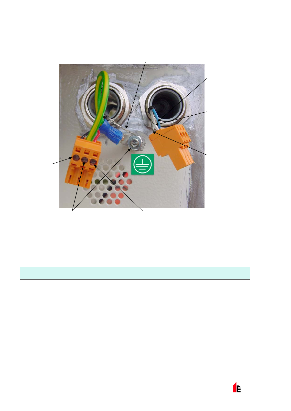
The following illustration shows the power and signal c onnec tions to the docki ng station for connection to
a single SenseNET cable:
Power Supply Screen Wire to Earth Stud
SenseNET/RS485
Bus A Wire
SenseNET/RS485
Bus B Wire
Power Supply
0V Wire
Wire from "Earth" Termi nal to Earth Stud Power Supply +24V Wire
SenseNET/RS485
Bus Screen Wire
3.2 Final installation
Once the power and signal c onnec tions are made slide the detector body up into the docking stati on and
fasten it into position using the M4 pan head screws provi ded. Slot the power and signal terminal blocks
into the rel ev ant socket s on the detector PCB (they will only cli c k fully home in the correct orient ation) and
replace the detector cover using the four M3 pan head screws provided.
NOTE: The detect or i s designed solely for operation with the front cover securely fitt ed using all four fixing
screws.
Removing the detector is simply the reverse of this proces s, leaving the pipe-work and wiring connecti ons
installed in the docking station.
© 2010 Hochiki Europe (UK) Lt d
9-5-0-345/ISS4/OCT10
Page 27
FIRElink-100 – Installation Manual Page 27 of 40
Dock Fixing
Screws
Cover Fixing
Screws x6
© 2010 Hochiki Europe (UK) Lt d
9-5-0-345/ISS4/OCT10
Page 28

Page 28 of 40 FIRElink-100 – Installation Manual
4 Interfacing
Because of the flexible nature of the FIREli nk - 100 detector and the many possible confi gur ations, there
are many options f or i nterfacing the detectors to the Fi re Panel. These include many third party
interfac es available from various manuf acturers. Because of this, it is not possible to give a complete list
of all interfaci ng m ethods but the following pages will give details of the most common methods that ar e
likely to be used.
4.1 Setti ng the Detector Address
In order to identify itself to the PC, Command Module or fire panel, eac h detector needs to have a unique
address ranging from 1 to 127. The detector address is simply set on the red DIP switch SW1 at the
bottom left of the opened detector on the main circ uit board. T he switch sett ings are on for 1 and off for
0, and the detector addr ess is set as a 7-bit binary code (switc h 8 equates to a value of 128 and so is
outside the usable addres s range). An example is shown below.
The address equates to 01100011 in binary, or (1 x 1) + (1 x 2) + (0 x 4) + (0 x 8) + (0 x 16) + (1 x 32) +
(1 x 64) + (0 x 128) = 99.
The full range of av ailable addresses and their relevant switch settings are shown belo w:
© 2010 Hochiki Europe (UK) Lt d
9-5-0-345/ISS4/OCT10
Page 29
FIRElink-100 – Installation Manual Page 29 of 40
4.2 Connectin g a FIRElink-100 to a SenseNET/RS485
Detector Network
Up to 127 detector s may be link ed in a si ngle S enseNET bus, supporting a tot al length of wire between
adjacent detectors of up to 1.2km.
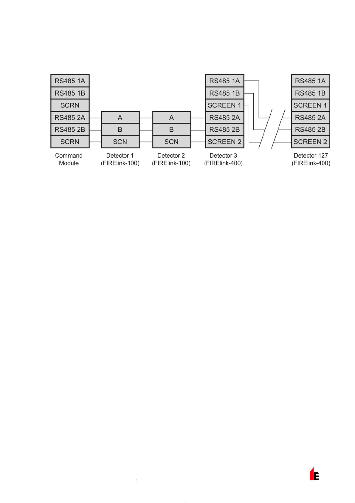
In the above example, two FIRElink-100 detect or s are link ed into a 127-detector bus with a Command
Module and a number of FIRElink-400 detectors. It will be noted that whereas the FIRElink-400 units
have two input / output buses (1A / 1B and 2A / 2B), the FIRElink-100 has only a single such bus (A / B)
and therefore each bus terminal has an input and an output wi r e, compared with a single wire i n each
terminal in the FIRElink-400.
For this reason, it may be easi er to join the input and output wires for each bus and screen connections
together and to sol der or crimp a si ngle wi r e or connect ing ferrule to each wire pair so that they are easier
to fit into the screw termi nals. If this is done it is recommended t hat bare wir e joints be insulated to
prevent possible shorting of the data bus, which will cause a drop-out of data on the SenseNET bus.
In the above example, there could be a total length of RS485 cable of up to 1.2km between the
Command Module and Det ector 3, sinc e these are all on a single bus. However, Detec tor 3 is a
FIRElink-400 whic h has a second communications bus (RS485 bus 2) and an RS485 repeater. This
allows a further total of 1.2km of cable until the next FIRElink-400 in the RS485 loop.
In the above example, if detectors 4-126 (not shown) were all of t he FI REli nk - 100 type then the total
length of wiri ng between detectors 3 and 127 would be limit ed to 1.2km. However, each additional
FIRElink-400 detector wired up using both RS485 buses woul d allow an additional 1.2km of cabling to be
added to the RS485 loop.
© 2010 Hochiki Europe (UK) Lt d
9-5-0-345/ISS4/OCT10
Page 30
Page 30 of 40 FIRElink-100 – Installation Manual
4.3 Connectin g a FIRElink-100 to an addressable Fire Panel
An Addressable Progr ammable Interface Card (FIRElink-APIC) may be used to decode det ec tor
information and to relay this to a Fire Panel.
The FIRElink -APIC is fitted to the four mounting studs on the FIREl ink-100 PCB using the supplied
screws as shown below:
FIRElink-APIC
Mounting Studs
(x 4)
FIRElink-APIC
Address Switches
(x 2)
FIRElink-APIC
Interface
Connection
The connections to the Fire Panel are made using the BUS L1 and H1 (bus 1 input and out put) and the
BUS L2 and H2 (bus 1 input and output) termi nal c onnec tors shown in Secti on 3.1. 4.
The only setti ngs that need to be made are on the FIRElink-APIC address DIP switches. The start loop
address Is entered on SW1 and the end loop address on SW2. In the case of a single FIRElink-100 the
start and end addresses will be the same.
© 2010 Hochiki Europe (UK) Lt d
9-5-0-345/ISS4/OCT10
Page 31
FIRElink-100 – Installation Manual Page 31 of 40
NOTE: The detect or address on the S enseNET loop and the Fire Panel addressable protocol address are
the same, in other words, no addre ss translation is performed. Some protocols may not support
all the available alarm levels and fault repor ting is usually a general fault wit h no detailed fault
information. Please consult the specifi c FIREl ink-APIC protocol documentation for more
inform ation.
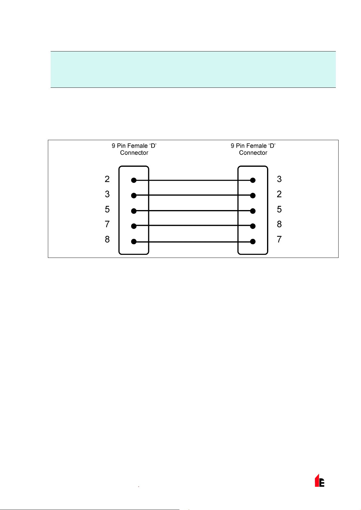
4.4 Connectin g to a PC
To connect a single stand- alone detector to a PC, connect the PC‘s serial port directly to the detector‘s 9way RS232 port, which i s sit uated on the bottom surface of t he detector case. Connections for this cable
are shown below:
© 2010 Hochiki Europe (UK) Lt d
9-5-0-345/ISS4/OCT10
Page 32
Page 32 of 40 FIRElink-100 – Installation Manual
5 Event Log
An event is defined as
a change to any programm ed function
a signal received from an external controller such as the r em ote software, FIREli nk - API C or
SenseNET
a detector out put level meeting or exceeding the P r e-Alarm , Aux, Fire 1 or Fire 2 alarm thresholds
a fault condition such as a flow or separator fault
start of day / night oper ation
demonstration mode start / stop
FastLearn start / stop
Power on or off
The detector stores an internal log of the last 200 events, and t his can either be viewed on a PC screen
or downloaded to disk by use of the remote control software.
When the event log is full ( 200 ev ents are stored) and a new event occurs, the oldest ev ent in the log is
deleted (Fi r st- In, First-Out).
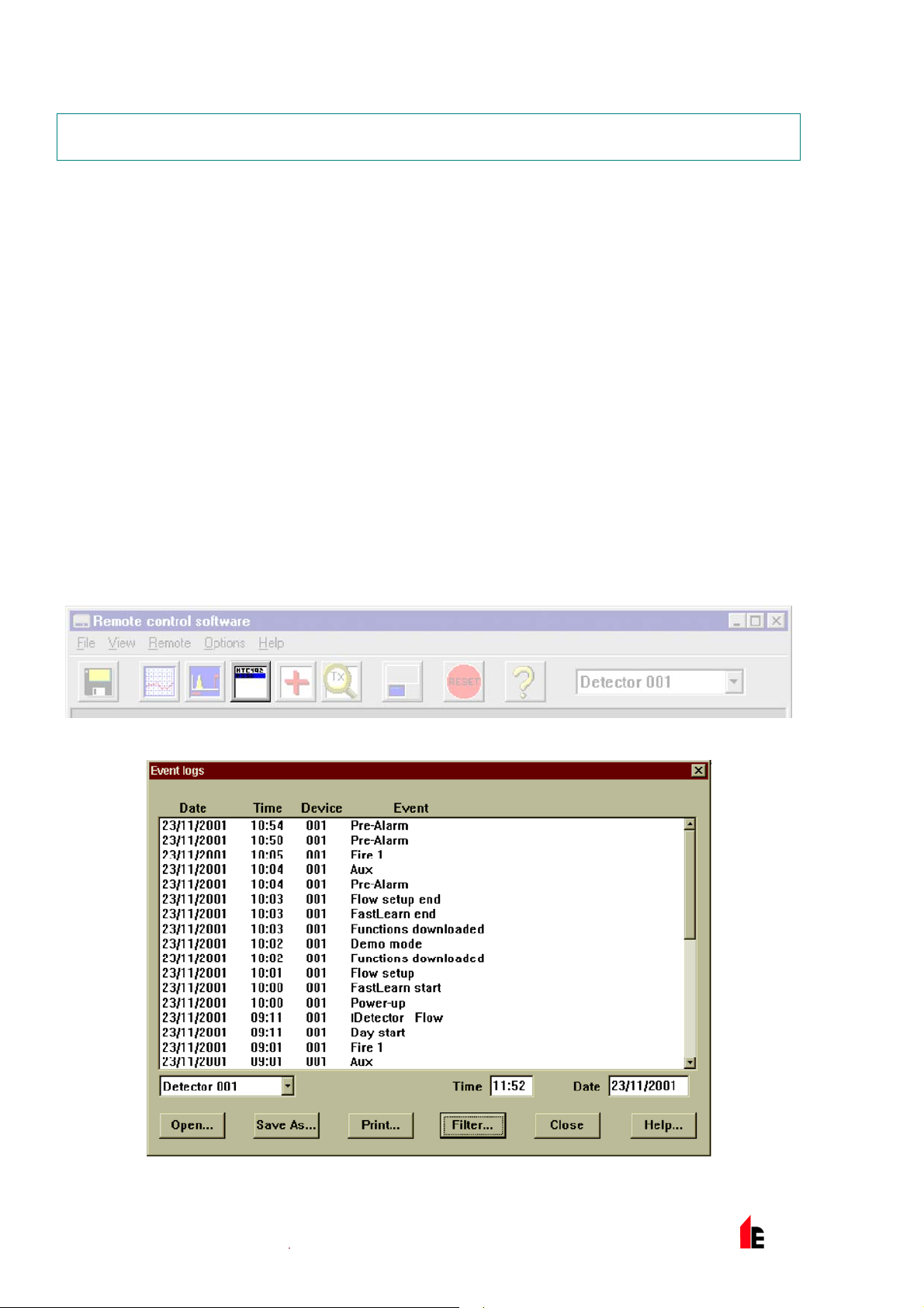
To download the ev ent log, c onnec t a PC to the detec tor serial port and run the remot e software. Either
select the menu options View > Event Log or click on the event log sym bol as i ndicated below:
The following screen will be displayed:
This shows the time and date of each event stored in the log along with it s general description. The
buttons at the bot tom of the screen allow control ov er the input and output of the log.
© 2010 Hochiki Europe (UK) Lt d
9-5-0-345/ISS4/OCT10
Page 33
FIRElink-100 – Installation Manual Page 33 of 40
Open: opens a previously saved event log. Event logs have t he file extension “.evl”.
Save As: saves the current event log as a .evl file with a user defined name.
Print: prints the ev ent log to a connected printer.
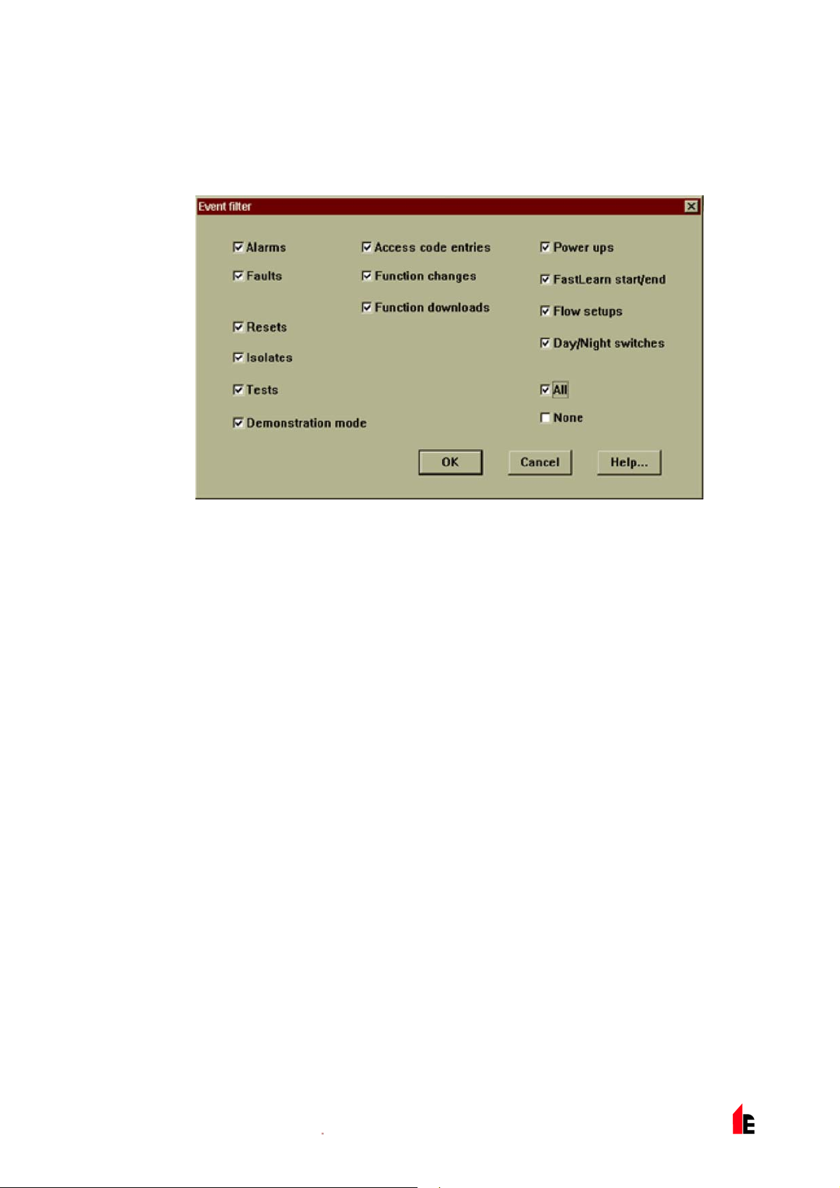
Filter: clicking on this option displays the f ollowing screen:
This allows the user to lim it the information printed or viewed on the PC screen. For example the user
might wish to concentr ate on alarm events only. To do this, click on “None”, which unticks all box es, and
then click on “Alarms”. To tick all the boxes, tick “All ”.
Any or all of the event categor ies may be selected or deselected as desir ed.
© 2010 Hochiki Europe (UK) Lt d
9-5-0-345/ISS4/OCT10
Page 34

Page 34 of 40 FIRElink-100 – Installation Manual
6 Commissioning
Before commissioning the detector t he loc al standar ds of aspi r ating detection systems must be consulted.
These standards differ widely throughout the world and specific advice for t he m arket in one c ountry may
not be applicabl e to another.
Commissioning str ategy will initially depend upon the environment in which the detector is installed. For
instance, t he test f or a comput er r oom (whic h shoul d be a r elatively clean env ir onm ent) would be very
different f rom, say, a flour mill, which would probably have a high level of airbor ne par ticulate content.
A widely accepted standard for computer rooms/EDP areas is British Standard BS6266, equipment
overheating at a stage well before combustion. To perform the test electrically overload a 1 metre lengt h
of PVC insulated wir e of 10/ 0.1mm gauge for one minute using an appropriate power supply. The
detector has two minutes from the end of the wire burn to giv e an alarm indication.
For areas with higher lev els of background particulate matter testing methodol ogy would be similar to that
of standard point detectors.
6.1 Commissioning Checklist
The following bri ef checklist allows quick setup of the detector. This procedure will be adequate for m ost
standard installations.
1. Before powering up the detector, visuall y chec k all c abling to ensure correct connection. If wire
identification is not immediatel y clear (for example, by use of different coloured wires or wire
identification sleeves) an elect ri cal check should be made. Any damage caused by misconnect ion of
the detector is not c ov er ed by warranty .
2. Power up the unit and connec t t o a PC and set the address swit c hes on the detector board (see
section 4.1) and FI REli nk - A PIC boar d if applicable (see secti on 4.3).
3. Verify that t he time and date are correct (see section 1.5)
4. Set an appropri ate alarm factor for the protect ed env ir onm ent. The detector will perform a FastLearn
for the new alarm factor. (see section 1.6.6)
5. Whilst the detector is still in FastLearn mode set the detector into demonstration mode (see section
3.10).
NOTE: Aerosol- type synt hetic smoke sources should not be used to test the response of the detector as
these may leave acidic r esi dues which could cause damage to the unit.
6. Wait for the FastLearn t o finish and the flashing OK LED indicat or will finish and perform any
necessary smoke tests, ensuring that the detector reacts appropriat ely (within 120 seconds f or LPCB
compliance), and let the smoke fully dissipate.
7. Perform anot her FastLearn, this time not putting the detector into demonstr ation mode. The detector
will generate no alarms during the 15 minute FastLearn per iod, and after thi s the detector will operate
at a reduced sensitivity for 24 hours whilst ClassiFire acclimatises to the protected environm ent and
sets up appropriat e day and night sensitivity settings.
© 2010 Hochiki Europe (UK) Lt d
9-5-0-345/ISS4/OCT10
Page 35
FIRElink-100 – Installation Manual Page 35 of 40
7 Maintenance
FIRElink-100 is a very low maintenance detection system. If required, ext er nal cl eaning of the unit should
be perform ed using a damp (not wet) cloth. Do not use solvents as these may mar the f r ont panel label.
The only part that m ay require field replacement during servicing is the dust separator assembly*. The
dust separator condition can be checked using the Dust Separator test in the Miscellaneous tab of the
remote software ‘Detector settings’ screen (see sect ion 1.12.3) that giv es a percentage reading of dust
separator efficiency. When this level drops to 80% the detector will si gnal a fault and the dust separator
will need replaci ng. To replace the filter, simply r em ove t he front cover and pull the filter out f r om the
main unit. Slide t he repl ac em ent fil ter in so that the ‘Direction of fl ow’ arrow pri nted on the carton
duplicat es t hat on t he ‘Dir ec tion of flow’ label beside t he filt er sl ot.
* It is recommended t hat dust separator s be changed at an interval of not m ore t han 3
years. After replacing the filter, the detector must be put into FastLearn m ode ( see
section 3.7) to reset the filter condition reading.
As dust contained i n the dust separator s may expose maintenanc e per sonnel to a ‘Nuisance Dust‘ hazard
as defined by the ‘Cont r ol of Substanc es Hazardous to Health‘ (COS HH) , it is strongly recommended that
suitable masks and protec tive clothi ng be worn when changing f ilters.
intended for re-use and should be disposed of.
Used separators are not
7.1 Diagnostics
The remote control software includes a diagnostic function that car ri es out a num ber of chec k s to verify
the correct func tioning of the detector. A good tim e to run these tests i s a s a part of planned
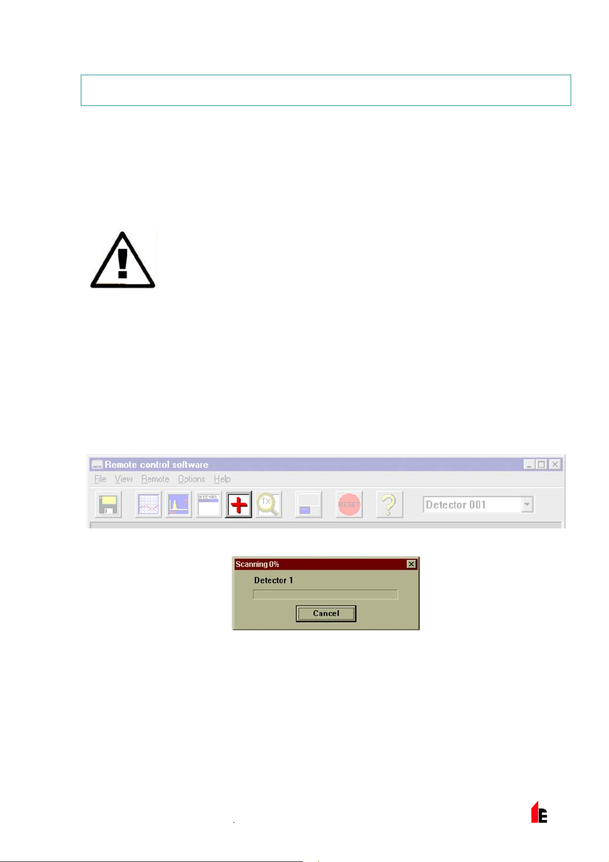
maintenance. To call up diagnostic mode, select t he menu options View > Diagnostics or clic k on t he
symbol indicated below:
The following message will be displayed:
The software will then scan the loop for up to 127 detectors. For a singl e detec tor, wait until the first
detector has been identified and the window indic ates that it is scanning for Detect or 2, t hen pr ess the
Cancel button.
The following window is di spl ay ed:
© 2010 Hochiki Europe (UK) Lt d
9-5-0-345/ISS4/OCT10
Page 36

Page 36 of 40 FIRElink-100 – Installation Manual
Click on the list entry to highlight it and click on t he Diagnostics button. The software will t hen
commence the system t ests. During the “Aspirator and flow” test, the detector fan will suddenly sl ow
down, but this is a normal par t of the t est.
When the test has finished and no problems have been found, the following screen is displ ay ed:
If any problems were f ound dur ing the diagnostic tests, the nat ur e of the fault will be indicated in the
“Status” column.
Scan: Reads in the status of all connected detector s.
Read Button: T his brings up a display of the detec tor output and flow rate which updates in r eal time.
Relays: Brings up a screen allowing t he function of the volt-free ‘Fire’ and F ault LEDs to be tested
with the aid of a continuity meter or other t ester . The Fire relay contacts are open i n
norm al oper ation and will close on test. The F ault relay contacts operate on a ‘Fail-safe’
basis and are held closed in normal operati on. They will therefore open on test.
Save As: Saves the summary list of scanned detectors and their status as a text (.txt) file.
Print: Print s the summary list to a connected printer.
© 2010 Hochiki Europe (UK) Lt d
9-5-0-345/ISS4/OCT10
Page 37

FIRElink-100 – Installation Manual Page 37 of 40
8 Troubleshooting
8.1 Nuisance Alarms Occur Too Often
Check that the Cl assiFi r e alarm factor setting is appropriate for the normal working environment of
the protect ed ar ea. See sect ion 1.6.4
Check that the detec tor is not in Demonstration mode. Thi s can be ascert ained by viewing the
event log (see section 1.4) and checking that the entry Demo mode has a higher log entry number
than the most recent F astLearn start and FastLearn end entr ies. Remember that the log entri es
are in reverse order, with the most recent entries appearing first. If the log shows that
Demonstration mode was invoked during the last F astLear n per iod, start a new FastLearn and
allow it to complet e its 24-hour cycle (see section 1.6.6).
From the event log (see section 5), check that 24 hours hav e elapsed since the last FastLearn end
entry.
Check that day- night switchover times are appropr iately set to reflect active and non-activ e peri ods
(see section 1. 7.1).
8.2 Elevated Smoke Levels Do Not Generate Alarms
Check that detect or is not Isolated or in FastLearn (if Isolated, the Fault light will be lit)
Check that the detec tor sampling points are in the smoke stream
Check that the corr ec t ClassiFire alarm setting has been set (see section 1.6.4)
Check that the detec tor has either had a 24 hour learning period or that it has been plac ed in
demonstration mode.
8.3 Low Mean Output
Check that the filter does not require changi ng ( see section 1.12.3) and that the air plenum
chamber is clean. The cham ber m ay becom e cl ogged when, f or ex am ple, heavy building activity
has occurred near the sampling pipes. If so, the chamber may r equire factory servic e. The
detector is not designed to handle large quantiti es of c oarse debris and du st.
8.4 Detector Sensi tivi ty Varies Over Time
There are many reasons why particle densities m ay vary, and the ClassiFire system automatically
compensates f or this in order to replace the likeli hood of nuisance alarms due to normal vari ations
in background sm ok e densi ty. Within limits set by the ClassiFir e alarm f actor, this is a normal part
of the detector‘s working.
8.5 Flow Fault Errors
These occur when the airf low rate into the detect or is outside t he pr e-programmed limits. As the
detector ‘l earns‘ the flow setup from the initi al installation, this usually means that there has been
some change in conditions. A Flow high fault may indicate that a sampling pipe is damaged, and a
Flow low fault may indi c ate that the pipe has been blocked, f or ex am ple, by nearby building
operations.
If the detect or i nput is sampled from one area and the exhaust is in another ar ea wi th different
pressure (for ex am ple, t he detector is in a roof space and sampling from an enclosed room), this
may lead to flow faults. In t his case it would be necessary to lead a pipe from the exhaust to the
© 2010 Hochiki Europe (UK) Lt d
9-5-0-345/ISS4/OCT10
Page 38

Page 38 of 40 FIRElink-100 – Installation Manual
protected area to ensure normal flow. This will requir e the det ec tor to be installed using the piped
exhaust docking station (see section 3.1).
8.5.1 "Low Flow" Error Messages.
Check that the pi pe giv ing the error is not blocked
Check that the low flow fault threshold is not set too high (see section 1.11.3)
8.5.2 "High Flow" Error Messages
Check that the pi pe is pushed home into the inlet and is not broken or crac k ed
Check that installed pipe-work is fitted with an end-cap. The FIRElink Pi peCA D® pipe modelling
software prom pts the use of appropriate end-caps.
Check that the hi gh flow fault threshold is not set too l ow (see section 1.11.2)
Open bore pipes are not recommended.
© 2010 Hochiki Europe (UK) Lt d
9-5-0-345/ISS4/OCT10
Page 39

FIRElink-100 – Installation Manual Page 39 of 40
9 Do's and Don'ts
DO
Ensure that the ClassiFire alarm factor i s appropriately set.
Ensure that cabl es are cor r ec tly connected before powering up by use of c able i dentifiers or
electric al c ontinuity checks. Incor r ect c onnec tion could damage the detector .
Ensure that cabl e of an appropr iate approved type is used for interconnection.
Place sampling points so that the detector will be abl e to detect smoke at the earliest opport unity.
Ensure that the det ec tor exhaust is in an area with the same atmospheric pressure as the sampling
pipes, eit her by pl aci ng the det ec tor physically in the protect ed ar ea or by leading a pipe from the
detector exhaust to the protected area.
Ensure that the envir onm ent of the protected area is within the environmental operat ing parameters
of the detector (tem per ature -10 to +60°C, (humidity 0-90%, non-condensing).
DON’T
Forget to set the appropr iate ClassiFire alarm factor for the area to be detected.
Forget to set the Det ector A ddr ess Switc hes corr ec tly when used in a net work.
Site detect or s i n damp or exposed areas.
Remove or connect boar ds when the detector is powered up.
Connect inter nal 0 v olt t erminals to local earth.
Attempt to re-use dust separat or c artridges once removed.
Attempt to adjust or alter detector settings other than via the user-programm able functions. In
particular , t he setting up of the laser is a precisi on task, and onc e set up the potentiometer s should
be left alone. If it is suspected that the laser alignment has shifted (for example, after dropping the
detector), it should be returned to Hochiki Europe ( UK ) Ltd for recalibration.
Place the detector near high power RF sources.
Operate the detector with the front cover remov ed, or with one or more of the cover fixing screws
loose or missing.
Test the response of t he detector using aerosol synthet ic smoke.
© 2010 Hochiki Europe (UK) Lt d
9-5-0-345/ISS4/OCT10
Page 40

Page 40 of 40 FIRElink-100 – Installation Manual
10 FIRElink-100 Specification
SELV Rating (EN 60950) Class III
21.6Vd.c. - 26.4Vd.c.
Supply Volt age
Size (mm) 300W x 220H x 85D
Weight 3.8kg with docking station
Operating Temperature Range
Operating Humidity Range
Measurement Range (obs/m)
Detection Princ iple Laser light scat tering mass detection
Particle Sensit iv ity Range 0.0003µm to 10µm
Current Consumpt ion 400mA @ 24Vd.c.
Relay Contact Rati ng 500mA @ 30Vd.c.
Maximum Sampling Pipe Length 100 metres total (see section 2 "Design Limitati ons" on page 20)
Sampling Pipe Inl ets 2
Sampling Pipe Internal Diameter 15-25mm
Alarm levels
Chamber Serv ic e Int ervals Greater than 8 years (depending on environment)
Dust Separator Repl ac em ent Intervals Greater than 5 years (depending on environment )
Laser Lifetime (MTTF) Greater than 1000 y ear s
Programming PC via RS232/RS485
Data Bus Cable RS485 data cable
Data Bus Length 1.2 km
IP Rating IP50
PSU Type: conforming to EN 54-4 El ectrical safety complies with
BS EN 610190-1
0 to +38°C (UL268)
-10 to +60°C (CEA4022)
0 - 90% Non Condensing
BS EN 61010-1 Poll ution degree 1
BS EN 61010-1 Installation Cat. II
0.03% to 25% Full Scale Deflection (FSD)
0.0015% to 25% Sensitiv ity Resolution
2 – "FIRE" and "FAULT" (2 additional levels available with
optional Relay Car d or FIREli nk - A P IC fitted)
NOTE: This equipm ent is only to be used in accordance with this specification. Failure to operate the
equipment as specif ied may cause damage to the unit.
© 2010 Hochiki Europe (UK) Lt d
9-5-0-345/ISS4/OCT10
 Loading...