

Page 1
GB WALL SOUNDER & WALL SOUNDER
BEACON INSTALLATION INSTRUCTIONS
DE MONTAGEANLEITUNG
SIGNALGEBER UND SIGNALGEBERBLITZLEUCHTE ZUR WANDMONTAGE
ES INSTRUCCIONES DE INSTALACIÓN
DE SIRENA DE PARED Y BALIZA CON
SIRENA DE PARED
FR GUIDE D'INSTALLATION POUR
DIFFUSEUR SONORE MURAL &
AVERTISSEUR SONORE MURAL
IT SIRENA DA PARETE E SIRENA CON
LAMPEGGIANTE DA PARETE: ISTRUZIONI
PER L’INSTALLAZIONE
NL WANDAUDIOALARM/BAKEN VOOR
WANDAUDIOALARM – INSTALLATIEINSTRUCTIES
PL INSTRUKCJA MONTAŻU ŚCIENNEGO
SYGNALIZATORA AKUSTYCZNEGO I
ŚCIENNEGO SYGNALIZATORA
AKUSTYCZNO-OPTYCZNEGO
RU УКАЗАНИЯ ПО МОНТАЖУ
НАСТЕННЫХ ЗВУКОВЫХ И
СВЕТОЗВУКОВЫХ ОПОВЕЩАТЕЛЕЙ
2-3-0-1752/ISS5/SEPT18
Page 2

GB WALL SOUNDER & WALL SOUNDER
BEACON INSTALLATION INSTRUCTIONS
PRODUCTS COVERED: CHQ-WS2, CHQWS2(WHT) Wall Sounders, CHQ-WSB2/WL,
CHQ-WSB2/RL, CHQ-WSB2(WHT)/RL,
CHQ-WSB2(WHT)/WL Wall Sounder
Beacons
COMPATIBLE BASES:
YBN-R/3(WHT)-SCI, YBO-R/3(RED), YBOR/3(WHT), YBO-R/SCI(RED)
INTRODUCTION
The CHQ-WS2 is a loop-powered addressable
wall sounder. The CHQ-WSB2 is a looppowered addressable wall sounder beacon.
Both units are compatible with the standard red
mounting base (YBO-R/3(RED)) and the red
isolator base (YBO-R/SCI(RED)); the units
have connections for both these types of base.
Do not attempt to use any other base type with
these units. Both sounders and bases are also
available in WHITE (YBO-R/3(WHT) (see
above).
Both the CHQ-WS2 and CHQ-WSB2 are
Ingress Protection rated to IP21C for internal
use, but can be made weatherproof when used
in conjunction with the CHQ-WPK Weather
Proofing Kit, in which case they are Ingress
Protection rated to IP65*
in accordance with the CHQ-WPK instructions
(2-3-0-627).
1
*
This product has only been approved to
IP33C by LPCB
1
but only when used
ADDRESS SETTING (WITH HAND HELD
PROGRAMMER)
The units will need to be manually addressed
between 1 and 127. The sounder address can
be set using the hand-held programmer (TCHB200) as the units both include the appropriate
terminals to fit directly onto the Programmer.
See the TCH-B200 instructions for further
details of address setting. The address must
be set before installation.
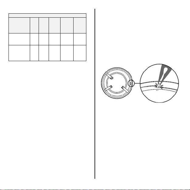
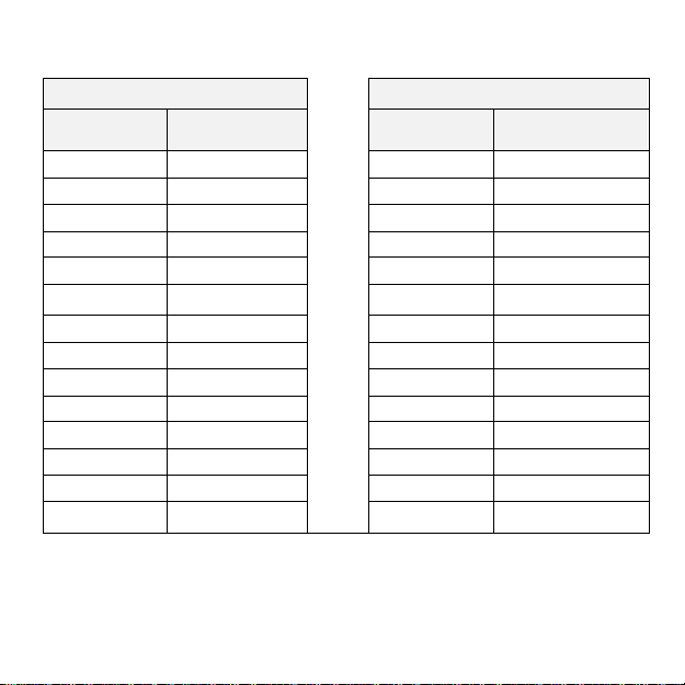
TONES AND VOLUMES
Table 1 below shows the full range of sound
outputs available from the CHQ-WS2 and
CHQ-WSB2 together with the amount of
current drawn when operated. The units are
also capable of utilising different EN54-3
Approved tones; these are listed in Table 2.
The tone of the sounder and the volume level
is selected and controlled by the control panel,
therefore check with the control panel
manufacturer for options and default values
available. The sounder and beacon elements
of the CHQ-WSB2 can be controlled
independently, check with the control panel
manufacturer for compatibility.
Page 3
)
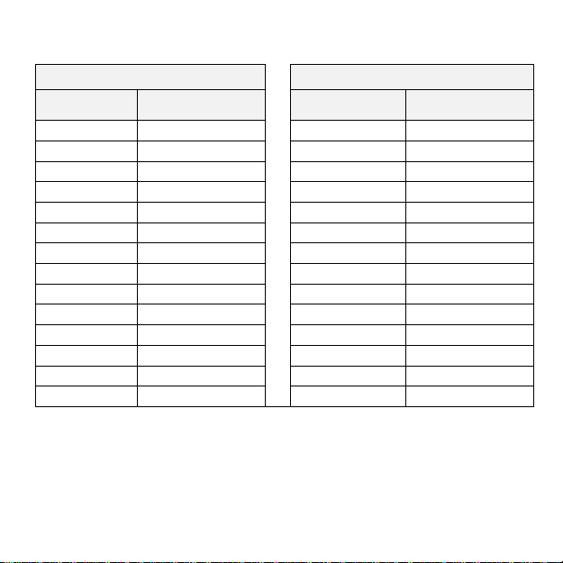
Table 1 – Current Drawn (mA)
Nominal
Sound
Output
dB(A)*
WS2
(sounder
activated)
WSB2
(sounder &
beacon
activated
Supply Voltage Range 17-41 Vdc. Max. Power
Consumption 287 mW @ 41 Vdc (beacon only).
* Refer to Application Notes AP084 and AP117
(available from our website) for complete EN54-3 Aweighted sound levels.
90 95 98 100 102
2.0 3.0 4.5 6.5 8.0
9.0 10.0 11.5 13.5 15.0
PRECAUTIONS
Ensure that the unit is installed in
accordance with Local Standards or
Regulations.
Only use the specified Hochiki mounting
bases (or CHQ-WPK Weather Proofing
Kit) with this wall sounder/wall sounder
beacon.
Only install in suitable environments, the
following in particular should be avoided:
o Excessively high ambient
temperature.
o Where excessive condensation or
moisture is present (unless CHQWPK is utilised).
o Hazardous areas.
A high voltage tester must not be used
with these units or either of the specified
bases.
E nsu re th at t he u nit is s ecur ely fix ed t o the
mounting base (and CHQ-WPK if
utilised).
For proper wiring supervision ensure that
the cables are wired as shown in fig 4.
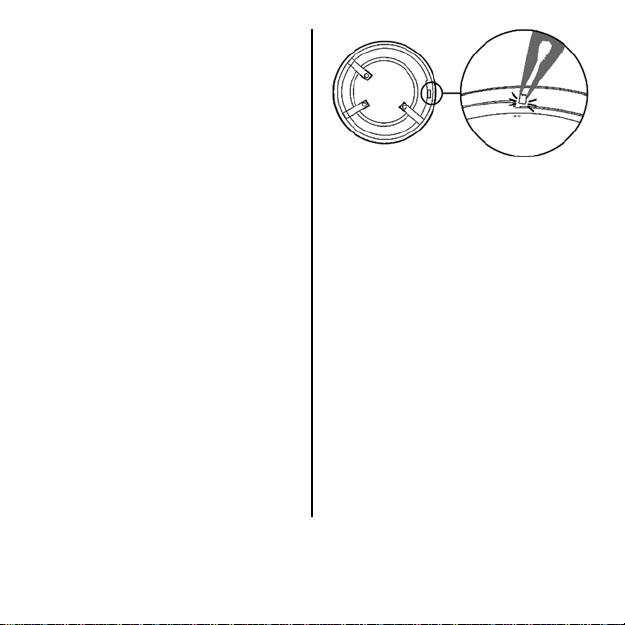
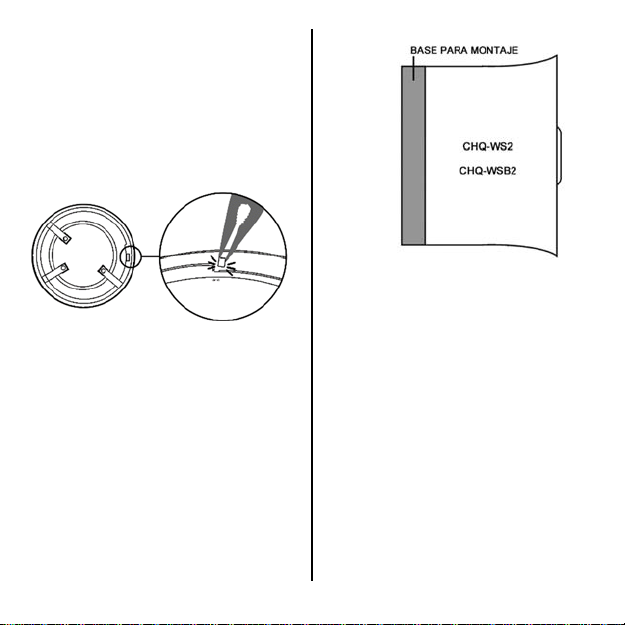
LOCKING MECHANISM
The units can be locked onto the relevant
mounting base by removing a plastic lug on the
underside of the sounder, refer to fig. 1.
fig 1
The unit can then only be removed from the
base by using a special removal tool, TSESRT, which is available from Hochiki Europe.
INSTALLATION
Both the CHQ-WS2 Wall Sounder and the
CHQ-WSB2 Wall Sounder Beacon are
designed to be mounted directly onto the Red
Standard Mounting Base
(YBO-R/3(RED)) or the Red Short-Circuit
Isolator Mounting Base
(YBO-R/SCI(RED)) or YBN-R/3(WHT)-SCI in
the same method as a Sensor (see fig. 2). The
terminals on the mounting base hold the units
in place.
Page 4
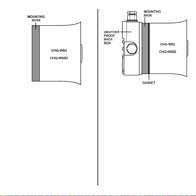
fig 2
Fix the mounting base to the required surface
using appropriate fixings. For correct wiring of
mounting base refer to fig. 4.
When installing either of these units in exterior
locations use the CHQ-WPK Weather Proofing
Kit. The kit consists of a weatherproof back
box and two gaskets, which must be used in
conjunction with either mounting base to
maintain the IP rating (see fig. 3). For further
information, refer to the CHQ-WPK Weather
Proofing Kit instructions (2-3-0-627).
fig 3
WIRING
Please refer to fig. 4 for wiring the Red
Standard Mounting Base (YBO-R/3(RED)) and
the Red Short-Circuit Isolator Mounting Base
(YBO-R/SCI(RED)):
TONES
All 51 tones generated by these devices are
EN54 compliant. Please refer to the following
documents available from our web site for
further details:
AP117 – Wall Sounder Beacon Tones &
Volumes
AP084 – Wall Sounder Tones & Volumes
The default tone is Tone 1 (9925 Hz : 250 ms/
628 Hz : 250 ms.
Page 5
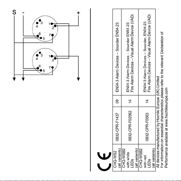
fig 4
(Refer to separate instructions
no. 2-3-0-1499 for YBN-R/3(WHT)-SCI wiring)
Page 6
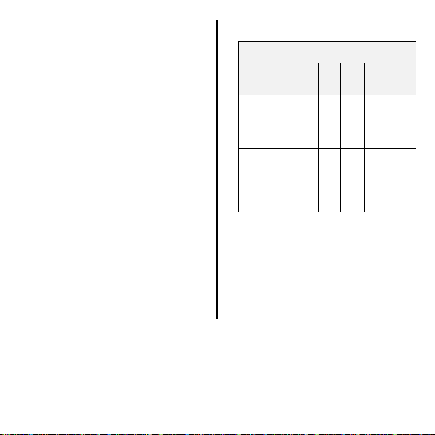
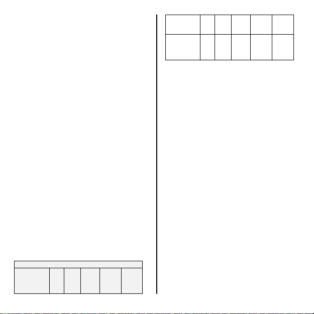
CHQ-WSB2 VOLUME/CURRENT COMPATIBILITY
YBO-BSB2 Setting
Sound Level
dB(A)
Off Quiescent
50 0.8
55 0.8
60 0.8
70 0.8
78 1.5
80 2.0
85 3.0
88 4.5
90 6.5
93 8.0
94 10
95 11
98 16
*Note that this is sounder current only. If the Beacon is operating please add 7mA to this
value.
Current mA
Corresponding CHQ-WSB2 Level
Sound Level
dB(A)
Off Quiescent
→
90 2.0
→
90 2.0
→
90 2.0
→
90 2.0
→
90 2.0
→
90 2.0
→
95 3.0
→
98 4.5
→
100 6.5
→
102 8.0
→
102 8.0
→
102 8.0
→
102 8.0
→
Current mA*
Page 7

If a control panel has not implemented the
CHQ-WSB2 then it will be recognised as a
YBO-BSB2. The table to the right shows the
volume level set as a YBO-BSB2 and the
corresponding level that is set on the CHQWSB2 by any panel configuration software that
recognises the CHQ-WSB2 as a YBO-BSB2.
For example, if 55dB(A) is selected on the
panel for a YBO-BSB2, the actual volume of
the CHQ-WSB2 will set to 90dB(A).
These differences in current should be taken
into consideration when calculating total loop
loading.
CHQ-WSB2 BEACON LIGHT COVERAGE
CHARACTERISTICS
The CHQ-WSB2/RL and CHQ-WSB2/WL are
“O” rated beacons designed in accordance
with EN54-23, please refer to application note
AP132 for the appropriate light output
volumetric coverage diagrams for each type.
Flash frequency O Rated ~ 0.5Hz (Default),
Compatibility Mode ~ 1Hz
DE MONTAGEANLEITUNG SIGNALGEBER
UND SIGNALGEBER-BLITZLEUCHTE ZUR
WANDMONTAGE
ABGEDECKTE PRODUKTE: CHQ-WS2,
CHQ-WS2(WHT) Wand-Signalgeber, CHQWSB2/WL, CHQ-WSB2/RL, CHQWSB2(WHT)/RL,
CHQ-WSB2(WHT)/WL WandSignalgeberblitzleuchten
KOMPATIBLE SOCKEL:
YBN-R/3(WHT)-SCI, YBO-R/3(RED), YBOR/3(WHT), YBO-R/SCI(RED)
EINFÜHRUNG
CHQ-WS2 ist ein adressierbarer Signalgeber
zur Wandmontage und zum Anschluss an eine
Ringleitung. CHQ-WSB2 ist eine
adressierbare Signalgeber-Blitzleuchte zur
Wandmontage und zum Anschluss an eine
Ringleitung. Beide Geräte sind mit dem roten
Standardsockel (YBO-R/3(RED)) und dem
roten Trennersockel (YBO-R/SCI(RED))
kompatibel und verfügen über Anschlüsse für
diese beiden Sockeltypen. Andere
Sockeltypen sich nicht kompatibel. Beide
Signalgeber und Sockel sind auch in WEISS
erhältlich (YBO-R/3(WHT) (siehe oben).
CHQ-WS2 und CHQ-WSB2 verfügen über die
Schutzart IP21C und sind zum Einsatz im
Innenbereich geeignet. In Verbindung mit dem
Wasserschutzset CHQ-WPK und bei dessen
fachgerechter Montage (2-3-0-627) lassen sie
sich zu Schutzart IP65*
*1LPCB-Zulassung nur für Schutzart IP33C
1
aufrüsten.
Page 8
MANUELLE ADRESSIERUNG (MITTELS
HANDPROGRAMMIERGERÄT)
Den Geräten müssen manuell Adressen
zwischen 1 und 127 zugewiesen werden. Die
Zuweisung der Signalgeber-Adresse erfolgt
mit dem Handprogrammiergerät (TCH-B200),
beide Geräte verfügen die entsprechenden
Anschlüsse. Weitere Informationen zur
Zuweisung von Adressen enthält die Anleitung
des TCH-B200. Die Adresse muss vor der
Montage festgelegt werden.
TÖNE UND SCHALLPEGEL
Tabelle 1 zeigt den gesamten Tonausgabebereich der Geräte CHQ-WS2 und CHQWSB2 sowie die beim Betrieb aufgenommene
Leistung. Die Geräte sind zur Ausgabe einer
Reihe gemäß EN54-3 zugelassener Töne
geeignet, diese sind in Tabelle 2 angegeben.
Die Auswahl und Steuerung von Ton und
Schallpegel des Signalgebers erfolgt durch die
Brandmelderzentrale, daher sind die verfügbaren
Optionen und Standardeinstellungen der
Brandmelderzentrale mit deren Hersteller
abzuklären. Signalgeber und Blitzleuchte des
CHQ-WSB2 lassen sich voneinander
unabhängig steuern. Kompatibilität der Brandmelderzentrale mit deren Hersteller abklären.
Tabelle1‐ Leistungsaufnahme(mA)
Nennschallpegel
dB(A)*
WS2
(Signalgeber
aktiv)
WSB2
(Signalgeberund
Blitzleuchte
aktiv)
Versorgungsspannung 17-41 Vdc. Max. Stromverbrauch 287 mW @ 41 Vdc (nur Blitzleuchte).
* Für umfassende EN54-3 A-gewichtete Schallpegelangaben, siehe Anwendungshinweise AP084 und
AP117 (auf unserer Website).
90 95 98 100 102
2,0 3,0 4,5 6,5 8,0
9,0 10,0 11,5 13,5 15,0
Page 9
VORSICHTSMAßNAHMEN
A
Bei der Montage des Geräts ist die
Einhaltung der regionalen Normen und
Vorschriften zu beachten.
Wand-Signalgeber und Wand-Signal-
geberblitzleuchte zur ausschließlichen
Nutzung mit den genannten Hochiki Sockeln
(bzw. dem CHQ-WPK Wasserschutzset).
Zur ausschließlichen Montage an
Standorten mit geeigneten Umwelt-
bedingungen. Insbesondere Folgendes
vermeiden:
o Zu hohe Umgebungstemperatur.
o Standorte mit übermäßiger
Kondensation oder Feuchtigkeit
(außer bei Nutzung von CHQWPK).
o Gefahrenzonen.
Hochspannungsprüfer von den genann-
ten Geräten und Sockeln fernhalten.
Den sicheren Sitz des Geräts am Sockel
(und, wenn genutzt, am CHQ-WPK)
sicherstellen.
Zum korrekten Anschluss sicherstellen,
dass dieser gemäß Abb. 4 erfolgt.
ENTNAHMESICHERUNG
Die Geräte lassen sich in Montageposition im
Sockel verriegeln, indem die Kunststoffzunge
an der Unterseite des Sockelsignalgebers
entfernt wird (siehe Abb. 1).
bb. 1
Zum Abnehmen des Geräts ist der Spezialschlüssel (TSC-SRT) erforderlich. Dieser ist
bei Hochiki Europe erhältlich.
MONTAGE
Der CHQ-WS2 Wand-Signalgeber und die
CHQ-WSB2 Wand-Signalgeberblitzleuchte
sind wie Melder zur Montage direkt auf dem
roten Standardsockel (YBO-R/3(RED)) oder
dem roten Trennersockel (YBO-R/SCI(RED))
bzw. auf dem YBN-R/3(WHT)-SCI konzipiert
(siehe Abb. 2). Die Klemmen des Sockels
sorgen für den sicheren Sitz des Geräts.
Page 10
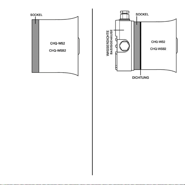
Abb. 2
Den Sockel mit geeigneten Befestigungen an
der gewünschten Oberfläche anbringen. Zum
richtigen Anschluss des Sockels, siehe Abb. 4.
Bei der Montage der Geräte im Außenbereich
ist die Nutzung des Wasserschutzsets CHQ-
WPK erforderlich. Das Set besteht aus einem
wasserdichten Basisgehäuse und zwei
Dichtungen, die zur Aufrechterhaltung der
Schutzart bei beiden Sockeln genutzt werden
müssen (siehe Abb. 3). Für weitere
Informationen, siehe Anleitung Wasserschutz-
set CHQ-WPK (2-3-0-627).
Abb. 3
ANSCHLUSS
Zum Anschluss des roten Standardsockels
(YBO-R/3(RED)) und des roten Trennersockels (YBO-R/SCI(RED)), siehe Abb. 4:
TÖNE
Alle 51 von diesen Geräten erzeugten Töne
sind EN54-konform. Weitere Informationen
enthalten die folgenden, auf unserer Website
verfügbaren Dokumente:
AP117 – Töne und Schallpegel Wand-Signalgeberblitzleuchten
AP084 – Töne und Schallpegel Wand-Signalgeber
Der Standardton ist Ton 1 (9925 Hz : 250 ms/
628 Hz : 250 ms.
Page 11
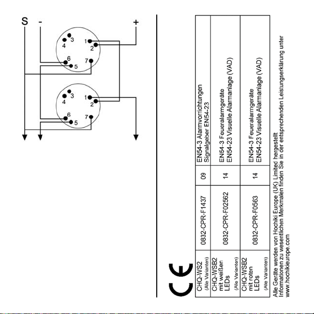
Abb. 4
(Siehe separate Anleitung
Nr. 2-3-0-1499 zum Anschluss von YBN-
R/3(WHT)-SCI)
Page 12
LAUTSTÄRKE CHQ-WSB2 / KOMPATIBILITÄT LEISTUNGSAUFNAHME
Einstellungen YBO-BSB2 Entsprechung CHQ-WSB2
Schallpegel
dB(A)
Aus Bereitschaft → Aus Bereitschaft
50 0,8 → 90 2,0
55 0,8 → 90 2,0
60 0,8 → 90 2,0
70 0,8 → 90 2,0
78 1,5 → 90 2,0
80 2,0 → 90 2,0
85 3,0 → 95 3,0
88 4,5 → 98 4,5
90 6,5 → 100 6,5
93 8,0 → 102 8,0
94 10 → 102 8,0
95 11 → 102 8,0
98 16 → 102 8,0
* Achtung, Angabe bezieht sich lediglich auf die Leistungsaufnahme des Signalgebers.
Beim Betrieb der Blitzleuchte steigt der angegebene Wert um 7 mA.
Leistungsaufnahme
mA
Schallpegel dB(A)
Leistungsaufnahme
mA*
Page 13

Brandmelderzentralen ohne CHQ-WSB2-
Implementierung erkennen CHQ-WSB2 als
YBO-BSB2. Die Tabelle rechts zeigt den
jeweiligen YBO-BSB2-Schallpegel und dessen
Äquivalenzwert bei Nutzung einer Brand-
melderzentrale, die CHQ-WSB2 als YBO-
BSB2 erkennt.
z.B. : erfolgt auf der Brandmelderzentrale die
YBO-BSB2-Auswahl 55dB(A), wird als tat-
sächlicher Schallpegel von CHQ-WSB2
90dB(A) gewählt.
Die gesteigerte Leistungsaufnahme ist bei der
Berechnung der Gesamtbelastung der Ring-
leitung zu berücksichtigen.
CHQ-WSB2 LICHTSTÄRKE-
EIGENSCHAFTEN
CHQ-WSB2/RL und CHQ-WSB2/WL sind
EN54-23-konforme Blitzleuchten der Klasse
„O“, für Informationen zur entsprechenden
Lichtleistung, siehe Anwendungshinweis
AP132 Volumetrische Abdeckungsdiagramme
je Typ. Blitzfrequenz Klasse O ~ 0,5 Hz (Vor-
gabewert), Kompatibilitätsmodus ~ 1 Hz
ES INSTRUCCIONES DE INSTALACIÓN DE
SIRENA DE PARED Y SIRENA DE PARED
CON FLASH
PRODUCTOS DESCRITOS: Sirenas de
pared CHQ-WS2, CHQ-WS2(WHT), sirena de
pared con flash. CHQ-WSB2/WL, CHQWSB2/RL, CHQ-WSB2(WHT)/RL,
CHQ-WSB2(WHT)/WL
BASES COMPATIBLES:
YBN-R/3(WHT)-SCI, YBO-R/3(RED), YBOR/3(WHT), YBO-R/SCI(RED)
INTRODUCCIÓN
La CHQ-WS2 es una sirena de pared
direccionable con alimentación por lazo. La
CHQ-WSB2 es una sirena de pared con flash
direccionable con alimentación por lazo.
Ambas unidades son compatibles con la base
de montaje roja estándar (YBO-R/3(RED)) y la
base con aislador roja (YBO-R/SCI(RED)); las
unidades incluyen conexiones para ambos
tipos de base. No intente usar ningún otro tipo
de base con estas unidades. Tanto las sirenas
como las bases también están disponibles en
BLANCO (YBO-R/3(WHT) (ver arriba).
Tanto la CHQ-WS2 como la CHQ-WSB2
cuentan con la clasificación IP21C para uso
interno, pero pueden adaptarse para la
intemperie cuando se usan en conjunto con el
kit a prueba de intemperie CHQ-WPK, en cuyo
caso ofrecen protección IP65*
cuando se usan en conformidad con las
instrucciones CHQ-WPK (2-3-0-627).
1
*
Este producto solo ha sido homologado
con clasificación IP33C por LPCB
1
pero solo
Page 14
AJUSTE DE DIRECCIÓN (CON
)
)
PROGRAMADOR PORTÁTIL)
Las unidades deberán direccionarse
manualmente entre 1 y 127. La dirección de la
sirena se puede ajustar con el programador
portátil (TCH-B200) ya que ambas unidades
incluyen los terminales apropiados que se
conectan directamente en el programador.
Para obtener más detalles sobre el ajuste de
dirección, consulte las instrucciones del TCH-
B200. La dirección se debe ajustar antes de la
instalación.
TONOS Y VOLÚMENES
La Tabla 1 a continuación muestra el margen
completo de salidas de sonido disponibles de
la CHQ-WS2 y la CHQ-WSB2 junto, con la
cantidad de corriente que consumen en
funcionamiento. Las unidades también tienen
capacidad para usar diferentes tonos
aprobados por la norma EN54-3. Consulte la
lista en la Tabla 2.
La central de incendio selecciona y controla el
tono y el nivel de volumen de la sirena; por lo
tanto, consulte con el fabricante para conocer
las opciones y los valores predeterminados
disponibles. Los elementos de sirena y sirena
con flash de la CHQ-WSB2 se pueden
controlar de manera independiente. Consulte
con el fabricante del la central de incendio para
conocer la compatibilidad.
Tabla 1 – Consumo (mA)
Salida
sonora
nominal
dB(A)*
90 95 98 100 102
WS2
(sirena
activada
WSB2
(sirena y
baliza
activadas
Fuente de alimentación de 17 a 41 V cc. Consumo
máx. de alimentación 287 mW @ 41 V cc (flash
solamente).
* Consulte las notas de aplicación AP084 y AP117
(disponibles en nuestra web) para ver todos los
niveles de sonido de ponderación A según EN54-3.
2,0 3,0 4,5 6,5 8,0
9,0 10,0 11,5 13,5 15,0
PRECAUCIONES
Asegúrese de que la unidad se instale de
acuerdo con las normas y las
regulaciones locales.
Solo utilice las bases de montaje Hochiki
especificadas (o el kit a prueba de
intemperie CHQ-WPK) con esta sirena de
pared/sirena de pared con flash.
Solo debe instalarse en entornos
apropiados; deberán evitarse
especialmente las siguientes
condiciones:
o Temperatura ambiente excesiva.
o Lugares con excesiva
condensación o humedad (salvo
que se utilice CHQ-WPK).
o Áreas peligrosas.
No deben usarse medidores de alta
tensión con estas unidades ni ninguna de
las bases especificadas.
Asegúrese de que la unidad esté bien
firme en la base de montaje (y CHQ-WPK
Page 15
si se utiliza).
Para un control adecuado de la
instalación eléctrica, asegúrese de tender
los cables como se muestra en la fig. 4.
MECANISMO DE BLOQUEO
Las unidades pueden bloquearse en la base
de montaje respectiva si se quita la lengüeta
plástica que se encuentra en la cara inferior de
la sirena, consulte la fig. 1.
fig 1
Ahora la unidad solo podrá retirarse de la base
con una herramienta de extracción especial,
TSC-SRT, que puede conseguir en Hochiki
Europe.
INSTALACIÓN
Tanto la sirena de pared CHQ-WS2 como la
sirena con flash de pared CHQ-WSB2 están
diseñados para instalarse directamente sobre
la base de montaje roja estándar (YBO-
R/3(RED)) o la base de montaje roja con
aislador de cortocircuito (YBO-R/SCI(RED)) o
la YBN-R/3(WHT)-SCI del mismo modo que un
sensor (ver fig. 2). Los terminales en la base
de montaje sujetan las unidades en su lugar.
fig 2
Fije la base de montaje sobre la superficie
requerida con las sujeciones apropiadas. Para
la correcta instalación eléctrica de la base de
montaje, consulte la fig. 4.
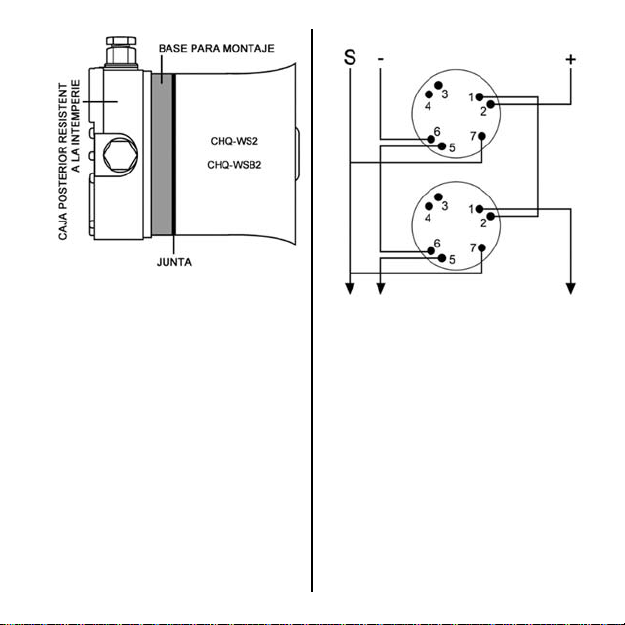
Cuando instale alguna de estas unidades en el
exterior, use el kit de intemperie CHQ-WPK. El
kit consta de una caja posterior resistente a la
intemperie y dos juntas, que se deben usar en
conjunto con cualquiera de las bases de
montaje para conservar la clasificación IP (ver
fig. 3). Para mayor información, consulte las
instrucciones del kit de intemperie CHQ-WPK
(2-3-0-627).
Page 16
628 Hz : 250 ms.
fig 3
INSTALACIÓN ELÉCTRICA
Consulte la fig. 4 para conectar la base de
montaje roja estándar (YBO-R/3(RED)) y la
base de montaje roja con aislador de
cortocircuito (YBO-R/SCI(RED)):
TONOS
Los 51 tonos que producen estos dispositivos
están en cumplimiento con EN54. Consulte los
siguientes documentos disponibles en nuestra
web para conocer más detalles:
AP117 – Wall Sounder Beacon Tones &
Volumes
AP084 – Wall Sounder Tones & Volumes
El tono por defecto es el nº. 1 (9925 Hz: 250
ms/
fig 4
(Consulte las instrucciones específicas
nro. 2-3-0-1499 para la instalación eléctrica de
YBN-R/3(WHT)-SCI)
Page 17

Page 18

COMPATIBILIDAD ENTRE VOLUMEN/CORRIENTE DEL CHQ-WSB2
Configuración de YBO-BSB2
Nivel sonoro
dB(A)
Apagado Reposo
50 0,8
55 0,8
60 0,8
70 0,8
78 1,5
80 2,0
85 3,0
88 4,5
90 6,5
93 8,0
94 10
95 11
98 16 → 102 8,0
*Tenga en cuenta que se refiere a la corriente de la sirena solamente. Si funciona el flash,
añada 7 mA a este valor.
Consumo mA
Nivel del CHQ-WSB2 correspondiente
Nivel sonoro
dB(A)
Apagado Reposo
→
90 2,0
→
90 2,0
→
90 2,0
→
90 2,0
→
90 2,0
→
90 2,0
→
95 3,0
→
98 4,5
→
100 6,5
→
102 8,0
→
102 8,0
→
102 8,0
→
Consumo mA*
Page 19

Si la CHQ-WSB2 no ha sido implementada con
una central de incendio, será reconocida como
una YBO-BSB2. La tabla de la derecha
muestra el nivel de volumen ajustado como
una YBO-BSB2 y el nivel correspondiente que
se ajusta en la CHQ-WSB2 con cualquier
software de configuración de la central que
reconoce la CHQ-WSB2 como YBO-BSB2.
Por ejemplo, si se selecciona 55 dB(A) en la
central para YBO-BSB2, el volumen real de la
CHQ-WSB2 se ajustará en 90 dB(A).
Estas diferencias en la corriente se deben
tener en cuenta cuando se calcula la carga
total del lazo.
CARACTERÍSTICAS DE ALCANCE DE LA
LUZ DEL FLASH CHQ-WSB2
El CHQ-WSB2/RL y el CHQ-WSB2/WL son
unidades flash con calificación “O” diseñadas
en conformidad con EN54-23. Consulte la nota
de aplicación AP132 para conocer los
diagramas de alcance volumétrico de salida de
luz apropiada para cada tipo. Frecuencia de
parpadeo calificación O a 0,5 Hz (prede-
terminado), Modo de compatibilidad ~ 1 Hz
FR GUIDE D'INSTALLATION POUR
DIFFUSEUR SONORE MURAL &
AVERTISSEUR SONORE MURAL
PRODUITS CONCERNÉS : Diffuseurs
sonores muraux CHQ-WS2, CHQ-WS2(WHT)
et avertisseurs sonores muraux CHQWSB2/WL, CHQ-WSB2/RL, CHQWSB2(WHT)/RL,
CHQ-WSB2(WHT)/WL
SOCLES COMPATIBLES :
YBN-R/3(WHT)-SCI, YBO-R/3(RED), YBOR/3(WHT), YBO-R/SCI(RED)
INTRODUCTION
Le CHQ-WSB2 est un diffuseur sonore et
lumineux mural adressable alimenté par
boucle. Ces deux dispositifs sont compatibles
avec le socle rouge standard (YBO-R/3(RED))
et le socle rouge avec isolateur (YBOR/SCI(RED)) ; ils disposent de connexions
pour ces deux types de socle. N'essayez pas
d'utiliser d'autres types de socle avec ces
dispositifs. Les diffuseurs et socles sont
également disponibles en BLANC (YBOR/3(WHT) (voir ci-dessus).
Le CHQ-WS2 et le CHQ-WSB2 possèdent
l'indice de protection IP21C pour un usage
intérieur, mais peuvent être étanches lorsqu'ils
sont combinés avec le kit d'étanchéité CHQWPK. Dans ce cas, ils possèdent l'indice
IP65*1 uniquement lorsqu'ils sont utilisés selon
les instructions du CHQ-WPK (2-3-0-627).
1
*
L'indice IP33C de ce produit a uniquement
été approuvé par LPCB
Page 20

CONFIGURATION DE L'ADRESSE
)
)
)
(PROGRAMMATEUR PORTABLE)
Les adresses des dispositifs devront être
configurées manuellement entre 1 et 127.
L'adresse du diffuseur sonore peut être
configurée à l'aide du programmateur portable
(TCH-B200) car les dispositifs comprennent
les bornes appropriés pour se connecter
directement au programmateur. Reportez-
vous aux instructions du TCH-B200 pour plus
de détails concernant la configuration de
l'adresse. L'adresse doit être configurée avant
l'installation.
SONORITÉS ET VOLUMES
Le tableau 1 indique la gamme complète de
puissances sonores disponibles avec le CHQ-
WS2 et le CHQ-WSB2 et la consommation de
courant lorsqu'il fonctionne. Les dispositifs
peuvent également utiliser différentes
sonorités homologuées par la norme EN 54-3,
et listées dans le tableau 2.
La sonorité du diffuseur et le volume sont
sélectionnés et contrôlés par l'ECS. Par
conséquent, adressez-vous au fabricant de
l'ECS pour connaître les options et les valeurs
disponibles par défaut. Le diffuseur sonore et
l'avertisseur du CHQ-WSB2 peuvent être
contrôlés indépendamment. Vérifiez la
compatibilité auprès du fabricant d'ECS.
Tableau 1 –Courant consommé (mA
Puissance
sonore
nominale
dB(A)*
WS2
(diffuseur
sonore
activé
WSB2
(diffuseur
sonore &
avertisseur
activés
Plage de tensions d'alimentation 17-41 Vcc.
Consommation d'énergie max. 287 mW @ 41 Vcc
(avertisseur uniquement).
* Consultez les fiches AP084 et AP117 (disponible sur
notre site) pour connaître les différentes tonalités et
niveaux sonores homologués par la norme EN 54-3.
90 95 98 100 102
2,0 3,0 4,5 6,5 8,0
9,0 10,0 11,5 13,5 15,0
PRÉCAUTIONS
Assurez-vous que le dispositif est installé
conformément aux normes ou aux
règlementations locales.
Utilisez uniquement les socles de
montage spécifiés Hochiki (ou kit
d'étanchéité CHQ-WPK) avec ce
diffuseur/avertisseur sonore mural.
N'installez le dispositif que dans des
environnements adaptés. Évitez, en
particulier, les situations suivantes :
o Température ambiante trop élevée.
o Condensation ou humidité trop
importante (sauf si le CHQ-WPK
est utilisé).
o Zones dangereuses.
Page 21

N'utilisez pas de testeur haute tension
avec ces dispositifs ou les socles
spécifiés.
Assurez-vous que le dispositif est bien
fixé sur le socle (vérifiez également le
CHQ-WPK si utilisé).
Vérifiez que les câbles sont correctement
branchés en vous référant au schéma 4.
MÉCANISME DE VERROUILLAGE
Les dispositifs peuvent être verrouillés sur le
socle en retirant la languette en plastique qui
se trouve sur le dessous (voir fig. 1).
fig. 1
Dans ce cas, le dispositif ne peut être retiré
qu'en utilisant un outil spécial (TSE-SRT)
commercialisé par Hochiki Europe.
INSTALLATION
Le diffuseur sonore mural CHQ-WS2 et
l'avertisseur sonore mural CHQ-WSB2 sont
conçus pour être directement montés sur le
socle standard rouge (YBO-R/3(RED)), sur le
socle rouge avec isolateur de court-circuit
(YBO-R/SCI(RED)) ou sur le YBN-R/3(WHT)-
SCI, de la même manière qu'un détecteur (voir
fig. 2). Les bornes du socle maintiennent le
dispositif en place.
fig. 2
Fixez le socle sur la surface souhaitée à l'aide
de fixations adéquates. Veuillez vous référer
au schéma 4 pour un raccordement correct.
En cas d'installation de ces dispositifs en
extérieur, utilisez le kit d'étanchéité CHQWPK. Le kit comprend un boîtier arrière
étanche ainsi que deux joints et doit être
combiné avec le socle pour maintenir l'indice
IP (voir fig. 3). Pour plus d'informations,
veuillez consulter les instructions du kit
d'étanchéité CHQ-WPK (2-3-0-627).
Page 22

fig. 3
CÂBLAGE
Veuillez vous référer au schéma 4 pour le
câblage du socle standard rouge (YBO-R/3
ROUGE) et du socle rouge avec isolateur de
court-circuit (YBO-R/SCI ROUGE) :
SONORITÉS
Les 51 sonorités émises par ces appareils sont
conformes à la norme EN 54. Pour plus
d'informations, veuillez consulter les
documents suivants disponibles sur notre site
internet :
AP117 – Sonorités et volumes de l'avertisseur
sonore mural
AP084 – Sonorités et volumes du diffuseur
sonore mural
La sonorité 1 est configurée par défaut
(9925 Hz) : 250 ms/628 Hz : 250 ms.
fig. 4
(Pour le branchement du YBN-R/3-SCI
(BLANC), veuillez consulter les instructions
n° 2-3-0-1499)
Page 23

Page 24

COMPATIBILITÉ VOLUME/COURANT DU CHQ-WSB2
Configuration YBO-BSB2
Niveau sonore
dB (A)
Off Inactif
50 0,8
55 0,8
60 0,8
70 0,8
78 1,5
80 2,0
85 3,0
88 4,5
90 6,5
93 8,0
94 10
95 11
98 16 → 102 8,0
*Valeurs de courant pour diffuseur sonore uniquement. Veuillez ajouter 7 mA à ces valeurs
pour l'avertisseur.
Courant mA
Niveau correspondant CHQ-WSB2
Niveau sonore
dB (A)
Off Inactif
→
90 2,0
→
90 2,0
→
90 2,0
→
90 2,0
→
90 2,0
→
90 2,0
→
95 3,0
→
98 4,5
→
100 6,5
→
102 8,0
→
102 8,0
→
102 8,0
→
Courant mA*
Page 25

Si le CHQ-WSB2 n'a pas été exécuté par
l'ECS, il sera alors reconnu comme un YBO-
BSB2. Le tableau ci-contre indique le réglage
du volume pour le YBO-BSB2 et le volume
correspondant réglé sur le CHQ-WSB2 par
tout logiciel de configuration qui reconnaît le
CHQ-WSB2 en tant que YBO-BSB2.
Par exemple, si la valeur 55 dB (A) est
sélectionnée sur l'ECS pour un YBO-BSB2, le
volume du CHQ-WSB2 sera alors réglé à
90 dB (A).
Ces différences de courant doivent être prises
en compte lors du calcul de la charge totale de
boucle.
CARACTÉRISTIQUES DE COUVERTURE
LUMINEUSE DE L'AVERTISSEUR CHQ-
WSB2
Les avertisseurs CHQ-WSB2/RL et CHQ-
WSB2/WL sont classés O et conçus en
conformité avec la norme EN 54-23. Veuillez
consulter la fiche AP132 pour obtenir les
schémas des volumes de couverture
lumineuse appropriés pour chaque type.
Fréquence de clignotement classée O ~ 0,5Hz
(défaut), Mode compatibilité ~ 1Hz
IT SIRENA DA PARETE E SIRENA CON
LAMPEGGIANTE DA PARETE: ISTRUZIONI
PER L’INSTALLAZIONE
PRODOTTI: Sirene da parete CHQ-WS2,
CHQ-WS2(WHT); sirene e lampeggianti da
parete CHQ-WSB2/WL, CHQ-WSB2/RL,
CHQ-WSB2(WHT)/RL, CHQWSB2(WHT)/WL
BASI COMPATIBILI:
YBN-R/3(WHT)-SCI, YBO-R/3(RED), YBOR/3(WHT), YBO-R/SCI(RED)
INTRODUZIONE
La CHQ-WS2 è una sirena da parete
indirizzabile alimentata da loop. La CHQWSB2 è una sirena con lampeggiante da
parete indirizzabile alimentata da loop.
Entrambe le unità sono compatibili con la base
rossa standard (YBO-R/3(RED)) e la base
rossa con isolatore (YBO-R/SCI(RED)); le
unità hanno collegamenti per entrambi questi
tipi di base. Non provare a utilizzare nessun
altro tipo di base con queste unità. Sia le sirene
che le basi sono disponibili anche in BIANCO
(YBO-R/3(WHT)) (vedere sopra).
Sia la CHQ-WS2 che la CHQ-WSB2 sono
classificate IP21C per uso in interni secondo
quanto la normativa dei gradi di protezione, ma
possono essere rese impermeabili se utilizzate
insieme al Kit di resistenza alle intemperie
CHQ-WPK, nel qual caso sono classificate
1
IP65*
secondo la normativa dei gradi di
protezione, ma solo se usate in conformità alle
istruzioni CHQ-WPK (2-3-0-627).
*1 Questo prodotto è stato qualificato solo IP33C
dal LCBP
Page 26

IMPOSTAZIONE DELL’INDIRIZZO (CON
)
PROGRAMMATORE PALMARE)
L’indirizzo delle unità si dovrà impostare
manualmente da 1 a 127. È possibile
impostare l’indirizzo della sirena con il
programmatore palmare (TCH-B200) in
quanto entrambe le unità comprendono i
terminali idonei ad adattarsi direttamente al
programmatore. Per maggiori dettagli
sull’impostazione dell’indirizzo vedere le
istruzioni del TCH-B200. Impostare l’indirizzo
prima dell’installazione.
TONI E VOLUMI
La sottostante Tabella 1 mostra l’intera gamma
di suoni disponibile sulle CHQ-WS2 e CHQWSB2, oltre alla quantità di corrente assorbita
quando sono in funzione. Le unità sono anche
in grado di utilizzare una serie di vari toni
approvati dalla norma EN54-3 ed elencati nella
Tabella 2.
Il tono della sirena e il livello del volume si
selezionano e si controllano mediante la
centrale. Verificare pertanto le opzioni e i valori
predefiniti disponibili con il costruttore della
centrale. La sirena e il lampeggiante della
CHQ-WSB2 si possono controllare separatamente, verificare la compatibilità con il
costruttore della centrale.
Tabelle 1 – Corrente assorbita (mA)
Potenza
sonora
nominale
dB(A)*
WS2
(sirena
attivata
90 95 98 100 102
2,0 3,0 4,5 6,5 8,0
WSB2
(sirena e
lampeggiante
attivati)
Campo della tensione di alimentazione 17-41 VDC.
Consumo massimo di energia 287 mW a 41 VDC
(solo lampeggiante).
* Consultare le note applicative l’AP084 e AP117
(disponibili sul nostro sito web) per informazioni
complete sui livelli sonori ponderati A conformi alla
norma EN54-3.
9,0 10,0 11,5 13,5 15,0
PRECAUZIONI
Assicurarsi che l’unità sia installata in
conformità alla normativa e agli standard
locali.
Utilizzare solo le basi Hochiki specificate
(oppure il Kit di resistenza alle intemperie)
con questa sirena da parete/sirena con
lampeggiante da parete.
Installare solo in ambienti idonei, evitando
soprattutto quanto segue:
o Temperatura ambiente troppo
elevata.
o Luoghi con molta condensa o
umidità (salvo che non si utilizzi il
CHQ-WPK).
o Aree pericolose.
Assicurarsi che l’unità sia saldamente
fissata alla base (e al CHQ-WPK se
utilizzato).
Per il corretto controllo del cablaggio,
assicurarsi che i cavi siano installati come
illustrato nella fig. 4.
Page 27

SISTEMA DI BLOCCAGGIO
È possibile bloccare le unità alla relativa base
togliendo la linguetta di plastica sul lato
inferiore della sirena (vedere Fig. 1).
fig. 1
È possibile rimuovere l’unità dalla base
soltanto utilizzando uno speciale utensile di
smontaggio, il TSE-SRT, disponibile presso
Hochiki Europe.
INSTALLAZIONE
Sia la sirena da parete CHQ-WS2 sia la sirena
con lampeggiante da parete CHQ-WSB2 sono
progettate per essere montate direttamente
sulla base rossa standard (YBO-R/3(RED))
oppure la base rossa per l’isolatore di
cortocircuito (YBO-R/SCI(RED)) oppure YBNR/3(WHT)-SCI nella stessa modalità di un
sensore (vedere fig. 2). I terminali sulla base
tengono in posizione le unità.
fig. 2
Fissare la base alla superficie richiesta con gli
idonei fissaggi. Per il cablaggio corretto della
base fare riferimento alla fig. 4.
Quando si installa all’esterno una di queste
unità utilizzare il Kit di resistenza alle
intemperie CHQ-WPK. Il kit comprende una
scatola da incasso impermeabile e due
guarnizioni da utilizzare insieme alla base per
mantenere la classificazione IP (vedere fig.3).
Per ulteriori informazioni, consultare le
istruzioni del Kit di resistenza alle intemperie
CHQ-WPK (2-3-0-627).
Page 28

fig. 3
CABLAGGIO
Fare riferimento alla fig. 4 per il cablaggio della
base rossa standard (YBO-R/3(RED)) e per la
base rossa dell’isolatore di cortocircuito (YBOR/SCI(RED)):
TONI
I 51 toni generati da dispositivi sono tutti
conformi alla norma EN54. Per ulteriori
dettagli, consultare i seguenti documenti
disponibili sul nostro sito web:
AP117: toni e volumi per sirena con
lampeggiante da parete
AP084: toni e volumi per sirena da parete
Il tono predefinito è il Tono 1 (9925 Hz: 250 ms/
628 Hz: 250 ms.
fig. 4
(Consultare le istruzioni a parte n. 2-3-0-1499
per il cablaggio della YBN-R/3(WHT)-SCI
Page 29

Page 30

VOLUME CHQ-WSB2/COMPATIBILITÀ CORRENTE
Impostazione YBO-BSB2
Livello sonoro
dB(A)
Spento A riposo
50 0,8
55 0,8
60 0,8
70 0,8
78 1,5
80 2,0
85 3,0
88 4,5
90 6,5
93 8,0
94 10
95 11
98 16
*Si noti che la corrente è solo per la sirena. Se il lampeggiante è in funzione aggiungere al
valore 7 mA.
Corrente mA
Corrispondente livello CHQ-WSB2
Livello sonoro
dB(A)
Spento A riposo
→
90 2,0
→
90 2,0
→
90 2,0
→
90 2,0
→
90 2,0
→
90 2,0
→
95 3,0
→
98 4,5
→
100 6,5
→
102 8,0
→
102 8,0
→
102 8,0
→
102 8,0
→
Corrente mA*
Page 31

Se la centrale non ha implementato la CHQWSB2, questa sarà riconosciuta come YBOBSB2. La tabella a destra mostra il livello di
volume impostato sulla YBO-BSB2 e il
corrispondente livello impostato sulla CHQWSB2 da ogni software di configurazione della
centrale che riconosce la CHQ-WSB2 come
YBO-BSB2.
Per esempio, se sulla centrale si selezionano
55dB(A) per una YBO-BSB2, il volume effettivo
della CHQ-WSB2 sarà impostato a 90dB(A).
Queste differenze di corrente si dovrebbero
tenere in considerazione quando si calcola il
carico del loop.
CARATTERISTICHE DI DIFFUSIONE
DELLA LUCE DEL LAMPEGGIANTE CHQWSB2
I lampeggianti CHQ-WSB2/RL e CHQWSB2/WL sono classificati “O” e sono stati
progettati in conformità con la norma EN54-23,
consultare la nota applicativa AP132 per gli
schemi di diffusione volumetrica dell’idonea
potenza luminosa per ciascun modello.
Frequenza di lampeggio classificata O a 0,5 Hz
(predefinita), modalità di compatibilità ~ 1Hz
NL Wandsirene & Wandsirene flitser Installatie
Instructies
TOEPASSELIJKE PRODUCTEN: CHQ-WS2,
CHQ-WS2(WHT) Wandsirene,
CHQ-WSB2/WL, CHQ-WSB2/RL,
CHQ-WSB2(WHT)/RL,
CHQ-WSB2(WHT)/WL Wandsireneflitser
COMPATIBELE BASES:
YBN-R/3(WHT)-SCI, YBO-R/3(RED),
YBO-R/3(WHT), YBO-R/SCI(RED)
INLEIDING
De CHQ-WS2 is een door een lus
aangedreven adresseerbaar wandaudioalarm.
De CHQ-WSB2 is een lusgevoede
adresseerbare wandsireneflitser. Beide units
zijn compatibel met de standaard rode
montagebasis (YBO-R/3 (RED) en de rode
isolatorbasis (YBO-R/SCI (RED)); de units zijn
voorzien van aansluitingen voor beide typen
basis. Probeer geen ander type basis met deze
apparaten te gebruiken. Zowel de
audioalarmen als de bases zijn ook
beschikbaar in WIT (YBO-R/3 (WHT) (zie
hierboven).
Zowel de CHQ-WS2 als CHQ-WSB2 zijn
uitgerust met een IP21C-bescherming voor
intern gebruik, maar kunnen weerbestendig
gemaakt worden wanneer ze gebruikt worden
in combinatie met de CHQ-WPK
Weersbestendigheidskit, in welk geval ze
uitgerust zijn met een IP65*
maar alleen wanneer deze wordt gebruikt in
overeenstemming met de CHQ-WPKinstructies (2-3-0-627).
1
*
Dit product is alleen door LPCB
goedgekeurd voor IP33C
1
-bescherming
Page 32

INSTELLEN VAN HET ADRES (MET DE
–
Afg
)
g
)
HANDPROGRAMMEUR)
De units moeten handmatig tussen 1 en 127
worden geadresseerd. Het adres van het
audioalarm kan worden ingesteld met behulp
van de handprogrammeur (TCH-B200) omdat
de apparaten allebei de juiste klemmen
bevatten die direct op de programmeerunit
passen. Zie de instructies van de TCH-B200
voor meer informatie over het instellen van een
adres. Het adres moet vóór de installatie
worden ingesteld.
TONEN EN VOLUMES
Tabel 1 hieronder toont het volledige bereik
van geluidsuitgangen die beschikbaar zijn bij
de CHQ-WS2 en CHQ-WSB2 samen en de
hoeveelheid stroom die bij gebruik wordt
afgenomen. De units kunnen ook een aantal
verschillende EN54-3 goedgekeurde tonen
gebruiken; deze worden in tabel 2 vermeld.
De toon van de signaalgever en het
geluidsniveau worden geselecteerd en
gecontroleerd via het bedieningspaneel.
Controleer bij de fabrikant van het
bedieningspaneel welke opties en
standaardwaarden beschikbaar zijn. De
elementen van het audioalarm en het baken
van de CHQ-WSB2 kunnen onafhankelijk van
elkaar worden bediend, controleer de
compatibiliteit bij de fabrikant van het
bedieningspaneel.
Tabel 1
Nominale
audiooutput
dB(A)*
WS2
(audioalarm
geactiveerd)
WSB2
(audioalarm
en baken
eactiveerd
Voedingsspanningsbereik 17-41 Vdc. Max.
stroomverbruik 287 mW @ 41 Vdc (alleen baken).
* Raadpleeg toepassingsnota’s AP084 en AP117
(verkrijgbaar op onze website) voor complete EN54-3
A-gewogen geluidsniveaus.
enomen stroom (mA
90 95 98 100 102
2,0 3,0 4,5 6,5 8,0
9,0 10,0 11,5 13,5 15,0
VOORZORGSMAATREGELEN
Zorg ervoor dat de unit volgens de
plaatselijke normen of voorschriften is
geïnstalleerd.
Gebruik alleen de gespecificeerde
Hochiki-montagedozen (of CHQ-WPK
Weersbestendigheidskit) met dit
wandsireneflitser /baken voor
wandsirene.
Installeer de unit alleen in een daarvoor
geschikte omgeving. Met name de
volgende omstandigheden moeten
worden vermeden:
o Te hoge omgevingstemperatuur.
o Locaties waar overmatige
condensatie of vocht aanwezig is
(tenzij CHQ-WPK wordt gebruikt).
o Gevaarlijke ruimten.
Page 33

Er mag geen hoogspanningsmeter
A
worden gebruikt met deze apparaten of
met een van de aangegeven bases.
Controleer of de unit goed aan de
montagebasis is bevestigd (en CHQWPK indien gebruikt).
Controleer voor een correcte bedrading of
de kabels worden bedraad zoals in Afb. 4
is aangegeven.
VERGRENDELMECHANISME
De units kunnen op de betreffende
montagebasis worden vergrendeld door het
verwijderen van het kunststof lipje aan de
onderkant van de signaalgever (zie Afb. 1).
fb. 1
De unit kan dan alleen worden verwijderd met
behulp van een speciaal gereedschap, TSESRT, dat bij Hochiki Europe verkrijgbaar is.
INSTALLATIE
Zowel het CHQ-WS2 wandsirene als de CHQWSB2 wandsireneflitser zijn ontworpen om
direct op de rode standaard montagebasis te
worden gemonteerd. (YBO-R-R/3 (RED) of de
rode montagebasis voor de
kortsluitingsisolator (YBO-R/SCI (RED) of
YBN-R/3 (WHT)-SCI in dezelfde methode als
een sensor (zie Afb. 2). De aansluitklemmen
op de montagebasis houden de apparaten op
hun plaats.
Afb. 2
Bevestig de montagebasis met geschikte
bevestigingen aan het benodigde oppervlak.
Zie Afb. 4 voor de juiste bedrading van de
montagebasis.
Gebruik bij het installeren van een van deze
apparaten buitenshuis de CHQ-WPK Weerbestendigheidskit. Deze kit bestaat uit een
weerbestendige doos en twee pakkingen, die
in combinatie met een van beide montagevoetjes moeten worden gebruikt om de IPrating te behouden (zie Afb. 3). Raadpleeg
voor meer informatie de instructies van de
CHQ-WPK Weersbestendigheidskit (2-3-0-
627).
Page 34

Afb. 3
BEDRADING
Raadpleeg Afb. 4 voor het aansluiten van de
rode standaard montagebasis (YBNR/3(RED)) en de montagebasis voor de
kortsluitingsisolator (YBO-R/SCI(RED)):
TONEN
Alle 51 tonen die door deze apparaten worden
gegenereerd voldoen aan de EN54-norm.
Raadpleeg de volgende documenten op onze
website voor meer informatie:
AP117 – Tonen en volumes van baken van
wandaudioalarm
AP084 – Tonen en volumes van wandaudioalarm
De standaardtoon is Toon 1 (9925 Hz: 250 ms/
628 Hz: 250 ms.
Afb. 4
Raadpleeg de instructies
nr. 2-3-0-1499 voor YBN-R/3(WHT)-SCIbedrading)
Page 35

Page 36

CHQ-WSB2 VOLUME/STROOM COMPATIBILITEIT
Instelling YBO-BSB2
Geluidsniveau
dB(A)
Uit Rust
50 0,8
55 0,8
60 0,8
70 0,8
78 1,5
80 2,0
85 3,0
88 4,5
90 6,5
93 8,0
94 10
95 11
98 16
Let op: dit is alleen de stroom van de wandsirene. Als de flitser in werking is, tel dan bij
deze waarde 7mA op.
Stroom mA
Overeenkomstig CHQ-WSB2-niveau
Geluidsniveau
dB(A)
Uit Rust
→
90 2,0
→
90 2,0
→
90 2,0
→
90 2,0
→
90 2,0
→
90 2,0
→
95 3,0
→
98 4,5
→
100 6,5
→
102 8,0
→
102 8,0
→
102 8,0
→
102 8,0
→
Stroom mA*
Page 37

Als een bedieningspaneel niet van de CHQWSB2 is voorzien, wordt deze herkend als een
YBO-BSB2. In de tabel rechts ziet u het
volume dat als YBO-BSB2 is ingesteld en het
corresponderende niveau dat op de CHQWSB2 is ingesteld door een willekeurige
paneelconfiguratiesoftware die de CHQ-WSB2
als YBO-BSB2 herkent.
Als bijvoorbeeld 55dB (A) op het paneel is
geselecteerd voor een YBO-BSB2, wordt het
werkelijke volume van de CHQ-WSB2
ingesteld op 90dB(A).
Bij de berekening van de totale lusbelasting
moet rekening worden gehouden met deze
verschillen in stroomsterkte.
CHQ-WSB2 KENMERKEN VAN
FLITSERLICHTDEKKING
De CHQ-WSB2/RL en CHQ-WSB2/WL zijn
"O"-geclassificeerde flitsers ontworpen
volgens EN54-23, zie toepassingsnota AP132
voor de juiste lichtopbrengst. Volumedekkingsdiagrammen voor elk type Flitsfrequentie O-nominaal ~ 0,5Hz (fout) en
compatibiliteitsfunctie ~ 1Hz
PL INSTRUKCJA MONTAŻU ŚCIENNEGO
SYGNALIZATORA AKUSTYCZNEGO I
ŚCIENNEGO SYGNALIZATORA
AKUSTYCZNO-OPTYCZNEGO
UWZGLĘDNIONE PRODUKTY: Ścienne
sygnalizatory akustyczne CHQ-WS2, CHQWS2(WHT), CHQ-WSB2/WL, CHQ-WSB2/RL,
CHQ-WSB2(WHT)/RL,
Ścienne sygnalizatory akustyczno-optyczne CHQWSB2(WHT)/WL
KOMPATYBILNE PODSTAWY:
YBN-R/3(WHT)-SCI, YBO-R/3(RED), YBOR/3(WHT), YBO-R/SCI(RED)
WSTĘP
Sygnalizator CHQ-WS2 jest adresowalnym
ściennym sygnalizatorem akustycznym zasilanym
z pętli. Sygnalizator CHQ-WSB2 jest
adresowalnym ściennym sygnalizatorem
akustyczno-optycznym zasilanym z pętli. Obydwa
moduły są kompatybilne ze standardową
czerwoną podstawą montażową (YBO-R/3 (RED)
i czerwoną podstawą montażową z izolatorem
(YBO-R/SCI (RED)). Z tymi urządzeniami nie
należy podejmować prób stosowania podstaw
innego typu. Zarówno sygnalizatory akustyczne,
jak i podstawy są również dostępne w wersji
WHITE w kolorze białym (YBO-R/3 (WHT) (patrz
wyżej).
Zarówno CHQ-WS2 jak i CHQ-WS2 posiadają
stopień ochrony IP 21C do użytku wewnętrznego,
ale mogą być zastosowane jako odporne na
warunki atmosferyczne, gdy są używane w
połączeniu z zestawem CHQ-WPK Weather
Proofing Kit, w którym to przypadku posiadają
stopień ochrony IP 65*1, ale tylko wtedy, gdy
zostaną użyte zgodnie z instrukcją CHQ-WPK (23-0-627).
Page 38

*1Produkt ten został dopuszczony do
ą
)
stosowania w klasie ochrony IP 33C tylko przez
LPCB
USTAWIANIE ADRESU (PRZY POMOCY
RĘCZNEGO PROGRAMATORA)
Urządzenia wymagają ręcznego ustawienia
adresu w zakresie od 1 do 127. Adres
sygnalizatora akustycznego można ustawić za
pomocą ręcznego programatora (TCH-B200),
ponieważ oba urządzenia zawierają odpowiednie
zaciski, które pasują bezpośrednio do
programatora. Szczegółowe informacje na temat
ustawiania adresu można znaleźć w instrukcji
obsługi programatora TCH-B200. Adres należy
ustawić przed instalacją.
RODZAJE SYGNAŁÓW I ICH NATĘŻENIE
W tabeli 1 przedstawiono pełny zakres sygnałów
akustycznych dostępnych w sygnalizatorach CHQWS2 i CHQ-WSB2 wraz z wartościami poboru
prądu podczas pracy. Sygnalizatory mogą również
emitować szeroką gamę sygnałów akustycznych
zatwierdzonych normą EN54-3; sygnały te podano
w tabeli 2.
Rodzaj sygnału akustycznego emitowanego przez
sygnalizator oraz jego głośność można wybrać i
ustawiać za pomocą panelu sterowania, zatem
należy sprawdzić możliwości panelu udostępniane
w tym zakresie przez producenta. Elementy
sygnalizatora akustycznego i sygnalizatora
świetlnego systemu CHQ-WSB2 mogą być
sterowane niezależnie, należy sprawdzić
kompatybilność z producentem centrali alarmowej.
Tabela 1 – Pobór prądu (mA)
Nominalny
sygnał
akustyczny
dB(A)*
90 95 98 100 102
WS2
(sygnalizator
akustyczny
włączony)
WSB2
(sygnalizatory
akustyczny i
optyczny
czone
wł
Zakres napięcia zasilania 17-41 Vdc. Maks. pobór
mocy 287 mW @ 41 Vdc (tylko sygnalizator świetlny).
* Pełna lista wartości ciśnienia akustycznego
zgodnych z EN54-3 A znajduje się w notach
aplikacyjnych AP084 i AP117 (dostępne na naszej
stronie internetowej).
2,0 3,0 4,5 6,5 8,0
9,0 10,0 11,5 13,5 15,0
ŚRODKI OSTROŻNOŚCI
Należy upewnić się, że urządzenie zostało
zainstalowane zgodnie z lokalnymi normami
lub przepisami.
Z opisywanymi ściennymi sygnalizatorami
akustycznymi i ściennymi sygnalizatorami
akustyczno-optycznymi należy używać
wyłącznie podanych podstaw montażowych
firmy Hochiki (lub zestawu CHQ-WPK
Weather Proofing Kit).
Urządzenia należy montować w
odpowiednim otoczeniu, w szczególności
należy unikać:
o Nadmiernie wysokiej temperatury
otoczenia.
o Miejsc występowania nadmiernej
kondensacji lub wilgoci (chyba że
stosuje się zestaw CHQ-WPK).
o Stref niebezpiecznych.
W przypadku opisywanych urządzeń lub
podstaw nie wolno używać testera wysokiego
napięcia.
Page 39

Należy się upewnić, że urządzenie jest
bezpiecznie przymocowane do podstawy
montażowej (oraz do zestawu CHQ-WPK,
jeżeli jest wykorzystywany).
Podłączenie kabli należy wykonać zgodnie z
Rys. 4.
MECHANIZM ZATRZASKOWY
Urządzenia można umocować za pomocą
zatrzasku w odpowiedniej podstawie montażowej
usuwając plastikowy kołnierz ze spodniej części
sygnalizatora (patrz Rys. 1).
Rys. 1
Sygnalizator można wtedy zdemontować
wyłącznie za pomocą specjalnego narzędzia TSESRT dostępnego w Hochiki Europe.
MONTAŻ
Zarówno ścienny sygnalizator akustyczny CHQWS2 jak i ścienny sygnalizator akustycznooptyczny CHQ-WSB2 są przeznaczone do
montażu bezpośrednio na standardowej
podstawie montażowej w kolorze czerwonym
(YBO-R/3(RED)) lub na podstawie montażowej z
izolatorem zwarć (YBO-R/SCI(RED)) albo YBNR/3(WHT)-SCI w taki sam sposób jak czujnik patrz
Rys. 2). Zaciski na podstawie montażowej
utrzymują urządzenia we właściwym miejscu.
Rys. 2
Należy przymocować podstawę montażową do
żądanej powierzchni za pomocą odpowiednich
mocowań. Prawidłowe okablowanie podstawy
montażowej pokazano na Rys. 4.
W przypadku instalacji któregoś z tych urządzeń
na zewnątrz należy zastosować zestaw CHQWPK Weather Proofing Kit. Zestaw ten składa się
z odpornej na warunki atmosferyczne obudowy i
dwóch uszczelek, które muszą być stosowane w
połączeniu z jedną lub drugą podstawą
montażową w celu utrzymania wartości IP (patrz
Rys. 3). Więcej informacji można znaleźć w
instrukcji zestawu CHQ-WPK Weather Proofing Kit
(2-3-0-627).
Page 40

Domyślnym sygnałem dźwiękowym jest Sygnał 1
(9925 Hz: 250 ms/
628 Hz : 250 ms.
Rys. 3
PODŁĄCZENIE PRZEWODÓW
W celu podłączenia przewodów do standardowej
podstawy montażowej w kolorze czerwonym
(YBO-R/3(RED)) oraz podstawy montażowej z
izolatorem zwarć w kolorze czerwonym (YBOR/SCI(RED)) należy skorzystać z Rys. 4:
RODZAJE SYGNAŁÓW DŹWIĘKOWYCH
Wszystkie 51 sygnałów dźwiękowych
generowanych przez te urządzenia jest zgodnych
z normą EN54. W ięcej informacji można znaleźć w
poniższych dokumentach dostępnych na naszej
stronie internetowej:
AP117 – Sygnały dźwiękowe ściennego
sygnalizatora akustycznego i optycznego oraz ich
natężenie
AP084 – Sygnały dźwiękowe ściennego
sygnalizatora akustycznego oraz ich natężenie
Rys. 4
(Należy zapoznać się z odrębną instrukcją
nr 2-3-0-1499 odnośnie okablowania YBNR/3(WHT)-SCI)
Page 41

Page 42

STOSUNEK NATĘŻENIE DŹWIĘKU/PRĄD DLA CHQ-WSB2
Ustawienie YBO-BSB2
Poziom
głośności
dźwięku dB(A)
Wyłączony Spoczynkowy
50 0,8
55 0,8
60 0,8
70 0,8
78 1,5
80 2,0
85 3,0
88 4,5
90 6,5
93 8,0
94 10
95 11
98 16 → 102 8,0
Należy pamiętać, że jest to tylko sygnał dźwiękowy. Jeżeli działa sygnalizator optyczny, do
tej wartości należy dodać 7 mA.
Prąd mA
Odpowiadający poziom CHQ-WSB2
Poziom
głośności
dźwięku dB(A)
Wyłączony Spoczynkowy
→
90 2,0
→
90 2,0
→
90 2,0
→
90 2,0
→
90 2,0
→
90 2,0
→
95 3,0
→
98 4,5
→
100 6,5
→
102 8,0
→
102 8,0
→
102 8,0
→
Prąd mA
Page 43

Jeżeli w centrali nie zaimplementowano CHQWSB2, wtedy urządzenie zostanie rozpoznane
jako YBO-BSB2. Tabela po prawej stronie
przedstawia poziom głośności w ustawieniu dla
YBO-BSB2 oraz odpowiadający mu poziom
głośności w ustawieniu dla CHQ-WSB2 w
przypadku dowolnego oprogramowania
konfiguracyjnego centrali alarmowej
rozpoznającego CHQ-WSB2 jako YBO-BSB2.
Na przykład, jeżeli wybrana zostanie wartość 55dB
(A) na panelu dla YBO-BSB2, rzeczywisty poziom
głośności dla CHQ-WSB2 ustawiony zostanie na
90dB (A).
Różnice te należy uwzględnić przy obliczaniu
całkowitego obciążenia pętli.
CHARAKTERYSTYKA ZASIĘGU ŚWIETLNEGO
SYGNALIZATORA OPTYCZNEGO CHQ-WSB2
CHQ-WSB2/RL oraz CHQ-WSB2/WL są
sygnalizatorami optycznymi klasy “O”
zaprojektowanymi zgodnie z normą EN54-23.
Odpowiednie wartości strumienia świetlnego
można znaleźć w nocie aplikacyjnej AP132 wraz z
wykresami zasięgu wolumetrycznego dla każdego
z typów. Częstotliwość błysku klasy O ~ 0.5Hz
(Domyślnie), Tryb zgodności ~ 1Hz
RU УКАЗАНИЯ ПО МОНТАЖУ НАСТЕННЫХ
ЗВУКОВЫХ И СВЕТОЗВУКОВЫХ
ОПОВЕЩАТЕЛЕЙ
ИСПОЛЬЗУЕМЫЕ ПРОДУКТЫ: Настенные
звуковые оповещатели CHQ-WS2, CHQWS2(WHT), настенные светозвуковые
оповещатели CHQ-WSB2/WL, CHQ-WSB2/RL,
CHQ-WSB2(WHT)/RL,
CHQ-WSB2(WHT)/WL
СОВМЕСТИМЫЕ БАЗЫ:
YBN-R/3(WHT)-SCI, YBO-R/3(RED), YBOR/3(WHT), YBO-R/SCI(RED)
ВВЕДЕНИЕ
CHQ-WS2 — это настенный звуковой
оповещатель с питанием от шлейфа, имеющий
доступный адрес. CHQ-WSB2 — это настенный
светозвуковой оповещатель с питанием от
шлейфа, имеющий доступный адрес. Оба
устройства совместимы со стандартной
красной монтажной базой (YBO-R/3(RED)) и
красной базой с изолятором (YBO-R/SCI(RED));
коннекторы этих устройств подходят к обоим
типам этих баз. Запрещено использование для
данных устройств других типов баз. Оба
оповещателя и базы доступны в БЕЛОМ
варианте (YBO-R/3(WHT) (см. выше).
Устройства CHQ-WS2 и CHQ-WSB2 имеют
класс защиты от проникновения IP21C и
предназначены для использования в
помещениях, однако они могут быть защищены
от непогоды при использовании в комбинации с
комплектом для защиты от непогоды CHQWPK. В этом случае их класс защиты от
проникновения становится IP65*1, но только
при условии эксплуатации согласно указаниям,
применимым к комплекту CHQ-WPK (2-3-0-
627).
Page 44

*1Данное изделие сертифицировано по
д
)
классу IP33C Комитетом сертификации
предотвращения потерь
НАСТРОЙКА АДРЕСОВ (ПОРТАТИВНЫМ
ПРОГРАММИРУЮЩИМ УСТРОЙСТВОМ)
Необходима ручная адресация устройств в
диапазоне от 1 до 127. Адреса оповещателей
можно задать с помощью портативного
программирующего устройства (TCH-B200)
благодаря наличию в них соответствующих
клемм, рассчитанных на прямое подключение к
нему. Более подробная информация о
присвоению адресов приведена в руководстве
к устройству TCH-B200. Присвоить адреса
необходимо до монтажа.
ТИПЫ ТОНОВ И УРОВНИ ГРОМКОСТИ
В таблице 1 ниже приведен полный спектр
звуковых сигналов оповещателей CHQ-WS2 и
CHQ-WSB2, включая значения потребляемого
тока при функционировании. Кроме того, эти
устройства могут использовать различные
типы по стандарту EN54-3; они перечислены в
таблице 2.
Тип тона и уровень громкости звукового
оповещателя выбираются и контролируются на
контрольной панели, поэтому вам следует
узнать у производителя контрольной панели об
имеющихся опциях и значениях по умолчанию.
Оповещатель и световые элементы модели
CHQ-WSB2 могут управляться изолированно.
Совместимость следует уточнить у
изготовителя конкретной панели управления.
Таблица 1: Потребляемый ток (мA)
Ном. уровень
выходного
сигнала
Б(А)*
90 95 98 100 102
WS2
(оповещатель
активирован
WSB2
(оповещатель
и световой
сигнализатор
активированы)
Диапазон напряжений питания: 17...41 В пост. т.
Макс. потребляемая мощность: 287 мВт при 41 В
пост. т. (только световой сигнализатор)
* Ознакомьтесь с указаниями по применению
AP084 и AP117 (на нашем веб-сайте), в которых
приведен полный список уровней громкости звука
в соответствии со стандартом EN54-3 A.
2,0 3,0 4,5 6,5 8,0
9,0 10,0 11,5 13,5 15,0
МЕРЫ ПРЕДОСТОРОЖНОСТИ
Убедитесь в том, устройство установлено
в соответствии с местными стандартами и
нормами.
С данным настенным
оповещателем/светозвуковым
оповещателем допускается
использование только указанных
компанией Hochiki монтажных баз (или
комплекта для защиты от непогоды CHQWPK).
Устанавливайте оповещатель только в
пригодных для этого условиях; в
частности, необходимо избегать
установки в следующих условиях:
o крайне высокая температура
окружающей среды;
o наличие избыточной конденсации
или влаги (кроме случаев
использования комплекта CHQWPK).
Page 45

o опасные зоны.
Не допускается использование
измерителя высокого напряжения с
данными устройствами или с любой из
указанных баз.
Убедитесь в том, что устройство надежно
закреплено на монтажной базе (включая
комплект CHQ-WPK, если таковой
используется).
Для проверки правильности проводки
убедитесь в том, что провода
подсоединены так, как показано на рис. 4.
МЕХАНИЗМ БЛОКИРОВКИ
Устройства можно зафиксировать на
соответствующей монтажной базе
посредством удаления пластикового выступа
на нижней стороне оповещателя (см. рис. 1).
рис. 1
В этом случае демонтировать устройство
можно только с помощью специального
инструмента для демонтажа (TSC-SRT),
который можно приобрести в Hochiki Europe.
УСТАНОВКА
Настенный оповещатель CHQ-WS2 и
настенный светозвуковой оповещатель CHQWSB2 предназначены для установки
непосредственно на красную стандартную
монтажную базу (YBO-R/3(RED)) либо красную
монтажную базу с изолятором короткого
замыкания (YBO-R/SCI(RED)) либо YBNR/3(WHT)-SCI аналогично варианту с датчиком
(см. рис. 2). Устройство удерживается на
монтажной базе с помощью клемм.
рис. 2
Закрепить монтажную базу в нужном месте,
используя подходящий крепеж. Схема
проводных соединений приведена на рис.4.
При установке любого из данных устройств вне
помещений необходимо использовать
комплект CHQ-WPK. Комплект состоит из
задней крышки, защищающей от непогоды, и
двух прокладок, которые необходимо
использовать вместе с любой из монтажных
баз для соблюдения требований класса IP (см.
рис. 3). Подробная информация приведена в
инструкции к комплекту CHQ-WPK (2-3-0-627).
Page 46

рис. 3
ПОДКЛЮЧЕНИЕ ПРОВОДОВ
На рис. 4 приведена схема проводных
соединений красной стандартной монтажной
базы (YBO-R/3(RED)) и монтажной базы с
изолятором короткого замыкания (YBOR/SCI(RED)):
ТОНА
Каждый из 51 тона, генерируемый данными
устройствами, соответствуют стандарту EN54.
Подробности приведены в следующих
документах, доступных на нашем веб-сайте:
AP117: тона и громкость звучания настенных
светозвуковых оповещателей
AP084: тона и громкость звучания настенных
оповещателей
По умолчанию задан тон 1 (9925 Гц: 250 мс/
628 Гц: 250 мс
рис. 4
(см. отдельные инструкции № 2-3-0-1499
касательно проводных соединений модели
YBN-R/3(WHT)-SCI)
Page 47

Page 48

ГРОМКОСТЬ МОДЕЛИ CHQ-WSB2/СОВМЕСТИМОСТЬ ПО ТОКУ
Настройки модели YBO-BSB2
Уровень
громкости
дБ(A)
Ток, мА
Выкл. Бездействие
50 0,8
55 0,8
60 0,8
70 0,8
78 1,5
80 2,0
85 3,0
88 4,5
90 6,5
93 8,0
94 10
95 11
98 16
*
Это ток только оповещателя. При использовании светового оповещателя к этому значению
необходимо прибавить 7 мА.
Соответствующий уровень модели
CHQ-WSB2
Уровень
громкости
дБ(A)
Выкл. Бездействие
→
90 2,0
→
90 2,0
→
90 2,0
→
90 2,0
→
90 2,0
→
90 2,0
→
95 3,0
→
98 4,5
→
100 6,5
→
102 8,0
→
102 8,0
→
102 8,0
→
102 8,0
→
Ток, мА*
Page 49

Если для панели управления не используется
модель CHQ-WSB2, она будет распознана как
модель YBO-BSB2. В таблице справа показан
уровень громкости, заданный для модели YBOBSB2, и соответствующий уровень, заданный
на модели CHQ-WSB2 любой программой
настройки панели, которая распознает модель
CHQ-WSB2 как YBO-BSB2.
Например, если уровень 55 дБ(A) выбран на
панели для модели YBO-BSB2, фактическая
громкость модели CHQ-WSB2 будет
установлена на уровне 90 дБ(A).
Эти различия в токе следует принимать во
внимание при расчете общей нагрузки на
шлейфы.
УГОЛ ОХВАТА СВЕТОВОГО ЛУЧА МОДЕЛИ
CHQ-WSB2
CHQ-WSB2/RL и CHQ-WSB2/WL — это
световые сигнализаторы с номиналом «O»,
конструкция которых изготовлена согласно
стандарту EN54-23. В указании по применению
AP1 32 приве дены с оотве тств ующие объем ные
контуры рабочих зон со светоотдачей каждого
из этих типов.Частота вспышек, номинал «O» ~
0,5 Гц (по умолчанию), режим совместимости ~
1 Гц
Hochiki Europe (UK) Limited,
Gillingham Business Park,
Gillingham, Kent ME8 0SA
United Kingdom
T:+44(0)1634 260133
F: +44(0)1634 260132
E: sales@hochikieurope.com
W: www.hochikieurope.com
2-3-0-1752/ISS5/SEPT18
Page 50

(intentionally blank page)
Page 51

(intentionally blank page)
Page 52

 Loading...