

Page 1
Hochiki Europe (UK) Ltd
CHQ MODULES INSTALLATION INSTRUCTIONS
Products Covered: CHQ SZM (Single Zone Monitor), CHQ-DIM (Dual Input Monitor), CHQDZM (Dual Zone Module)
Introduction
The CHQ "Smart-Fix" Range of Modules consists of the following models:
CHQ-DIM(SCI)
CHQ-DIM/M(SCI)
CHQ-DIM/DIN(SCI)
CHQ-DRC(SCI)
CHQ-DRC/M(SCI)
CHQ-DRC/DIN(SCI)
CHQ-DSC(SCI)
CHQ-DSC/M(SCI) CHQ-SZM/M(SCI)
CHQ-DSC/DIN(SCI) CHQ-SZM/DIN(SCI)
Note: (SCI) indicates Module incorporates a short-circuit isolator. DIN indicates Module housing is designed to fit standard “Top
Hat” DIN Rail.
Dual Input Module
Dual Relay Controller
Dual Sounder Controller
Components
Standard "Smart-Fix" Modules (including (SCI) versions) are supplied as two individual components (see Fig 1 & 2). DIN versions
are supplied as one unit (see Fig 3).
CHQ-DZM(SCI))
CHQ-DZM/DIN(SCI)
CHQ-MRC(SCI)
CHQ-MRC/DIN(SCI)
CHQ-SZM(SCI)
Dual Zone Monitor
Mains Relay Controller
Single Zone Monitor
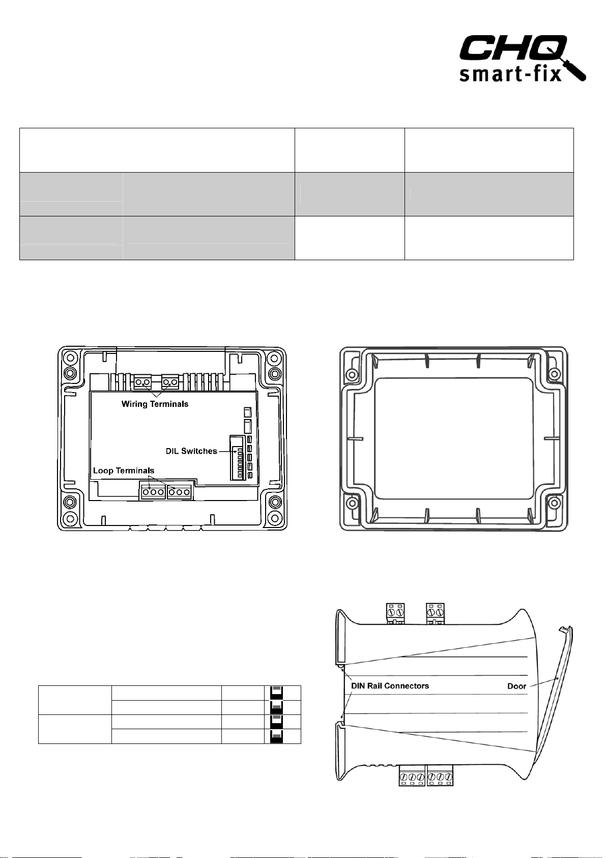
Fig 1
"Smart-Fix" CHQ Module (Back Plate inc PCB Component)
(Note: configuration of Wiring Terminal blocks differs between models)
Setting the Loop Address
The analogue address of the Module is set using the first 7
switches of the 8-bit DIL switch, which in the case of the
Standard CHQ is located through the cut-out section on the top
of the PCB cover. On the DIN version, this switch is located on
the edge of the PCB behind the clear door (see Fig 3).
The switches are numbered 1 to 8 (left to right):
CHQ MODULE
DIN MODULE
The switches should be set using a small-tipped screwdriver or
SWITCH UP
SWITCH DOWN
SWITCH UP
SWITCH DOWN
ON
OFF
OFF
ON
similar.
Refer to the Address Chart (Fig 9) on page 4 for a quick
reference on addresses.
(continued on page 4)
Fig 2
CHQ-LID Transparent Module Lid
(Supplied with four screws and acrylic retaining washers)
Fig 3
DIN Rail Mountable CHQ Module
Page 1 2-3-0-778/ISS8/DEC11
Page 2

Hochiki Europe (UK) Ltd
Order codes
CHQ
(SCI) /
(SCI) /
(SCI)
1
,
g
A
A
)
CHQ-DIM - DUAL INPUT MONITOR
This device is a loop-powered module designed to interface to a variety of inputs,
such as, door contacts, sprinkler flow/door switches and plant equipment fault
contacts, this module is particularly suited to applications where a fast response is
required to the input change.
Setting Contact Monitoring
Both volt free input contacts can be configured to be either N/O or N/C, by setting the
2-bit DIL switch
SWITCH 1 UP I/P 1 Normally Closed (N/C)
CHQ MODULE
Fig 4
DIN MODULE
LOOP CONNECTIONS: S = Cable Screen (if required), - = Loop Negative (-ve), + = Loop Positive (+ve)
Transmission method Digital communication using ESP
Operating voltage 17 - 41 VDC
Quiescent current
Current consumption whilst polling
280
A
22 mA 20 %
Current consumption with inputs active 4.3 mA (Both active)*2Input line resistance
Weight (g) &
Dimensions (mm)
CHQ-DIM(SCI)
CHQ-DIM/M(SCI)
CHQ-DIM/DIN(SCI) 113
327
Colour and enclosure material CHQ Module & CHQ-BACKBOX White ABS, DIN Module Green ABS
*1 Fire alarm control panel compatibility required for these products.
SWITCH 1 DOWN I/P 1 Normally Open (N/O)
SWITCH 2 UP I/P 2 Normally Closed (N/C)
SWITCH 2 DOWN I/P 2 Normally Open (N/O)
SWITCH 1 UP I/P 1 Normally Open (N/O)
SWITCH 1 DOWN I/P 1 Normally Closed (N/C)
SWITCH 2 UP I/P 2 Normally Open (N/O)
SWITCH 2 DOWN I/P 2 Normally Closed (N/C)
-DIM
CHQ-DIM/M
CHQ-DIM/DIN
Current in short-circuit 8 mA
Maximum short-circuit current (Loop) 1 A
ON threshold <50
OFF threshold >100 K
L157 x W127 x D35 (CHQ Module plus Lid)
D=79 (CHQ Module plus Lid plus CHQ-BACKBOX)
(add 235 to module weight when using CHQ-BACKBOX)
L108 x W119 x D24 (CHQ DIN Module)
2
Note: - Add 85A per input for normally closed contact monitorin
*
*
CHQ-DZM - DUAL ZONE MONITOR
This device is an externally powered module designed to allow up to 60
conventional detectors (30 per zone) to be interfaced to Hochiki’s ESP analogue
addressable system. The unit features three End Of Line (EOL) monitoring options
(see page 3 for further details).
Setting EOL Monitoring Option
Select the required EOL monitoring option using the 2-bit DIL switch.
SWITCH 1 DOWN
CHQ MODULE
SWITCH 2 DOWN
SWITCH 1 UP
SWITCH 2 DOWN
SWITCH 1 UP
SWITCH 2 UP
SWITCH 1 DOWN
SWITCH 2 UP
Fig 5
DIN MODULE
LOOP CONNECTIONS: S = Cable Screen (if required), - = Loop Negative (-ve), + = Loop Positive (+ve
ZENER
CTIVE/RESISTIVE
ZENER
CTIVE/RESISTIVE
Order codes CHQ-DZM(SCI) / CHQ-DZM/DIN(SCI) Transmission method Digital communication using ESP
Operating voltage 17 - 41 VDC
Low Power Mode (typ)
Quiescent current (typ)
110 A
330 A
Resistance on Zone (max) 50 Ω
Capacitance on Zone (max) 0.3 µF
Current consumption (external) (Quiescent) 2mA, (Alarm) 70mA (both zones in fire)
Current in short-circuit 8 mA Maximum short-circuit current (Loop) 1 A
Output rating 24 VDC 8.5 mA
DCA, DFB, DFE – No limit, SLG, SLK, SLR, SIF, SIH, SIJ, DCC, DCD, DFJ – 30 max,
Detectors per zone
SPB-ET, SPC-ET or SRA-ET– Only one and no other detectors, HF-24 – Only one and no other detectors,
DRD-E – 15 max, Conventional Call Points – No limit
Weights (g) &
Dimensions (mm)
CHQ-DZM(SCI) 350
CHQ-DZM/DIN(SCI) 130
L=157 x W=127 x D=35 (CHQ Module plus Lid)
D=79 (CHQ Module plus Lid plus CHQ-BACKBOX)
(add 235 to module weight when using CHQ-BACKBOX)
Colour and enclosure material CHQ Module & CHQ-BACKBOX White ABS, DIN Module Green ABS
*1 Fire alarm control panel compatibility required for these options.
Page 2 2-3-0-778/ISS8/DEC11
Page 3

Hochiki Europe (UK) Ltd
Standard EOL Options for CHQ-DZM
EOL Option Type Part Description
OPTION 1
Zener End of line device
(Zone)
OPTION 2
Active End Of Line Module
(Zone)
Active End Of Line
in conjunction with
Capacitor (Zone)
OPTION 3
Resistive EOL (Zone)
Monitored input EOL 10 KΩ resistor (2-2-5-806) 10 KΩ ± 5% 0.4W
TE-RH-E
Hochiki Part No 2-1-1-016
LCMU (6K8)
Hochiki Part No 1270070-00
(SUPPLIED SEPARATELY)
47 µF Capacitor
Hochiki Part No (2-2-7-031)
6K8 resistor (2-2-5-1015) 6K8 ± 5% 0.4 W
(Iz=1-mA, T=30ms, Vz=22.7 to 24.3 V)
L terminal connects to +Zone
C Terminal connects to -Zone
Active EOL - Line Continuity Monitoring Unit for Schottky bases (See Fig 6)
Pink lead connects to +Zone
Black lead connects to –Zone
47 µF ±20% 35 V
Fitted directly into Zone terminals (see Fig 6)
Fig 6
CHQ-SZM SINGLE ZONE MONITOR is a loop-powered module that provides a
single fully monitored input for the connection of up to six Hochiki conventional
smoke or heat detectors, OR one Hochiki beam detector, or any number of
conventional call points, the unit also contains an output for remote fire
indication.
Note: The end of line device
(EOL) is supplied with the unit –
do NOT discard in error! The
EOL device MUST be fitted at the
last detector on the zone, note the
polarity.
Fig 8
Fig 7
Order codes CHQ-SZM(SCI) / CHQ-SZM/M(SCI) / CHQ-SZM/DIN(SCI) *1
Transmission method Digital communication using ESP
Loop:-Operating voltage 17 - 41 VDC
Quiescent current
Current consumption whilst polling
Current in short-circuit 8 mA
Maximum short-circuit current (Loop) 1 A
E.O.L device TE-RH-E (polarity conscious)
Zone voltage 15.3 V - 17.1 V
Zone resistance
Zone capacitance
Detectors per zone
CHQ-SZM(SCI)
Weight (g) &
Dimensions (mm)
Colour and enclosure material CHQ Module & CHQ-BACKBOX White ABS, DIN Module Green ABS
* Fire alarm control panel compatibility required for these products. See AP0127 for short-circuit isolator specifications.
CHQ-SZM/M(SCI)
CHQ-SZM/DIN(SCI) 114
260 A
22 mA
50 (Max)
0.3 F (Max)
DCA, DFB, DFE – No limit, SLG, SLK, SLR, SIF, SIH, SIJ, DCC, DCD, DFJ – 6 max
SPB-ET or SRA-ET– Only one and no other detectors, HF-24 – Only one and no other
detectors, DRD-E – 3 max, Conventional Call Points – No limit
328
20 %
L157 x W127 x D35 (CHQ Module plus Lid)
D79 (CHQ Module plus Lid plus CHQ-BACKBOX)
(add 235 to module weight when using CHQ-BACKBOX)
L108 x W119 x D24 (CHQ DIN Module)
This module does not support any line continuity options; therefore, if Manual Call Points are to be interfaced then these should be
connected first.
Page 3 2-3-0-778/ISS8/DEC11
Page 4

Hochiki Europe (UK) Ltd
Installation – "Smart-Fix" Version
Set analogue address before installation (see page 1). The fixing
surface should be dry and stable.
Hold the back plate up against the fixing surface and mark the
position of the four corner fixing holes.
Determine which cut-out sections along the top and bottom
edges of the module require removing to accommodate the
cables being used.
Remove cut-outs by scoring with a sharp knife before breaking
off with pliers or snips.
Mount the back plate using appropriate fixings (not supplied) for
the fixing surface.
Terminate and connect field wiring as per the wiring diagrams
on pages 2 & 3 (and the terminal block indications on the
product label).
The transparent lid (CHQ-LID) is supplied with four screws and
eight retaining washers.
Push the screws through one of the retaining washers and then
through the holes in the lid from front to back, pushing another
retaining washer onto the end inside the lid.
Screw the lid onto the back plate; do not over tighten the
screws as this could damage the unit.
Note, a white plastic version of the lid is available (sold separately
– CHQ-LID(WHT)).
Installation with Back Box
Fig 9
For CHQ-DIM or CHQ-SZM installations requiring glanded cables, a module back box (CHQ-BACKBOX) is available (sold
separately). This is mounted on the fixing surface; the CHQ Module is then fitted to the top of the back box and the CHQLID is added creating a sealed enclosure. For further details refer to the CHQ-BACKBOX Instructions (2-3-0-800). For
CHQ-DZM installations utilising heavy-duty cabling (for example, 1.5mm
the SMB-ADAPTOR plate and CHQ-ADAPTOR is recommended.
(2-3-0-1502).
Ensure any glands used (not supplied) conform to IP67, if such ingress protection is required.
2
solid conductor) the use of the SMB-1 Box with
For further details refer to the SMB-ADAPTOR Instructions
Installation – DIN Version
Set analogue address before installation (see page 1) and write loop address in space provided on door label.
DIN modules should be mounted in a suitable enclosure in conjunction with an NS 35 mounting rail with the loop connections at
the bottom of the unit. Hochiki recommends the SMB-2 and SMB-3 Boxes designed specifically for this purpose.
Terminate and connect field wiring as per the wiring diagrams on pages 2 & 3 (and the terminal block indications on the product
label).
Suitable anti-static precautions must be taken when handling these products.
Status LEDs
Refer to the table below for Status LED indications:
CHQ-DIM (all variants) Dual Input Module
CHQ-SZM (all variants) Single Zone Monitor
CHQ-DZM (all variants) Dual Zone Monitor
CHQ-DIM(SCI) 0832-CPD-1098 09
CHQ-SZM(SCI) 0832-CPD-1094 09
Protocol specified in
TI/006
CHQ-DIM/DIN(SCI) 0832-CPD-1099 10
CHQ-SZM/DIN(SCI) 0832-CPD-1095 10
CHQ-DZM(SCI) 0832-CPD-1657 11
CHQ-DZM/DIN(SCI) 0832-CPD-1658 11
Green LED flashes each time the unit is polled by the fire alarm
control panel and is continuously illuminated when either input is
active (CHQ-DIM only). Amber LED is continually illuminated
when unit detects short-circuit fault.
EN54-17 Short Circuit Isolators
EN54-18 Input/Output Modules
Hochiki Europe (UK) Ltd
Grosvenor Road, Gillingham Business Park,
Gillingham, Kent, ME8 0SA, England
Telephone: +44(0)1634 260133
Facsimile: +44(0)1634 260132
Email: sales@hochikieurope.com
Web: www.hochikieurope.com
Hochiki Europe (UK) Ltd. reserves the right to alter the
specification of its products from time to time without
notice. Although every effort has been made to ensure the
accuracy of the information contained within this document
it is not warranted or represented by Hochiki Europe (UK)
Ltd. to be a complete and up-to-date description. Please
check our web site for the latest version of this document.
Page 4 2-3-0-778/ISS8/DEC11
 Loading...