

Page 1
2-1-0-024/ISS9/AUG03
HOCHIKI CHQ-MZ, CHQ-MZ/OEM & CHQ-MZ/DIN
MINI ZONE MONITOR INSTALLATION INSTRUCTIONS
Function
The CHQ-MZ is a loop powered module that provides a single fully monitored input for the connection of either up to
six Hochiki conventional smoke or heat detectors, one Hochiki Beam detector or any number of conventional call
points, the unit also contains an output for remote fire indication. The CHQ-MZ/DIN is the DIN Rail mounted version.
Specification
Order code CHQ-MZ* / CHQ-MZ/OEM* / CHQ-MZ/DIN*
Transmission method Digital communication using ESP
Loop:-Operating voltage 17 - 31 VDC
Quiescent current
260µA
Current consumption whilst polling
22 mA ± 20 %
E.O.L device TE-RH-E (polarity conscious)
Zone voltage 15.3V - 17.1V
Zone resistance
50Ω (Max)
Zone capacitance
0.3µF (Max)
Detectors per zone Number of conventional detectors per zone
DCA, DFB, DFE – No limit
SLG, SLK, SLR, SIF, SIH, SIJ, DCC, DCD, DFJ – 6 max
SPB-ET or SRA-ET– Only one and no other detectors
HF-24 – Only one and no other detectors
Conventional Call Points – No limit
Weights and Dimensions CHQ-MZ 120g, L=160 x W=110 x H=92mm
CHQMZ/OEM
75g, L=147 x W=90 x H=23mm
CHQ-MZ/DIN 106g, L=120 x W=23 x H=108mm
Colour and enclosure material CHQ-MZ
CHQMZ/OEM
CHQ-MZ/DIN
Grey, ABS (IP67 rated), c/w OEM module
White, ABS
Green ABS
* Fire alarm control panel compatibility required for these products.
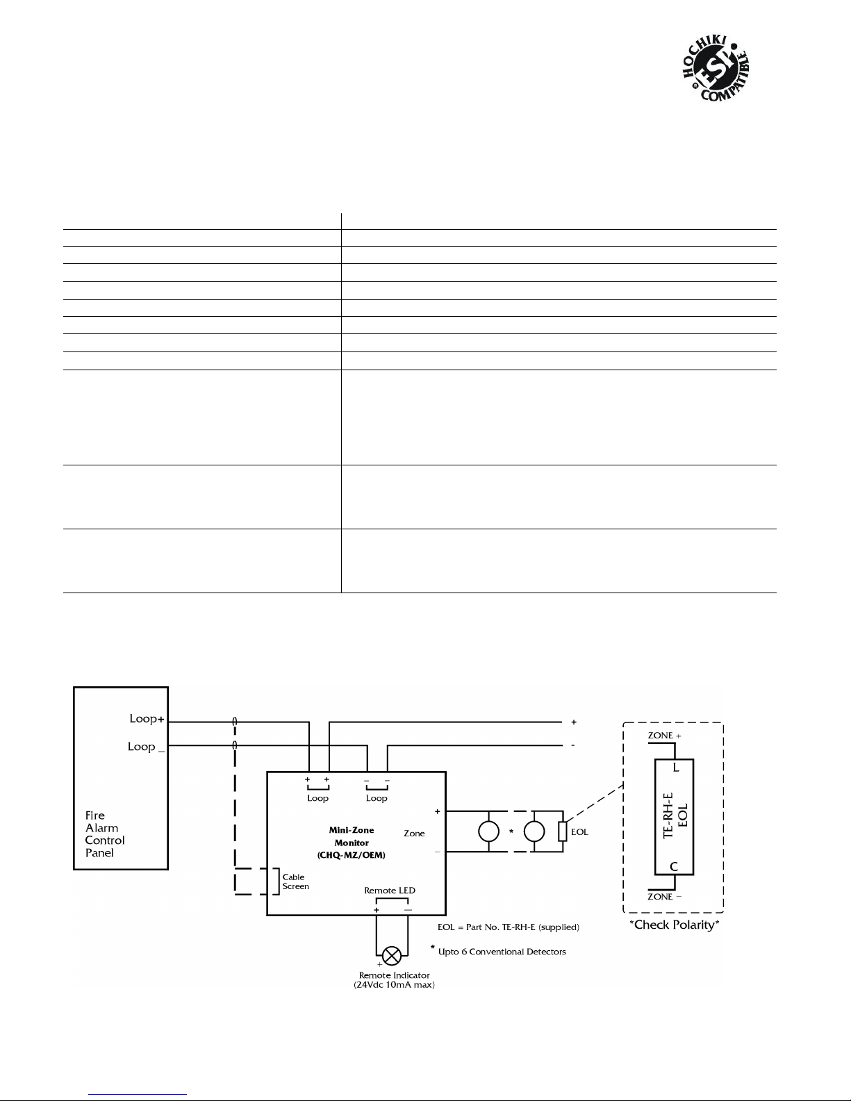
Note:- The End of Line device (part number TE-RH-E) is supplied with the unit.
Connection Details
Fig. 1
Page 2
2-1-0-024/ISS9/AUG03
The module should be connected to the loop as shown in Fig.1, the module does not support any line continuity
options, therefore, if manual Call Points are to be interfaced then these should be connected first.
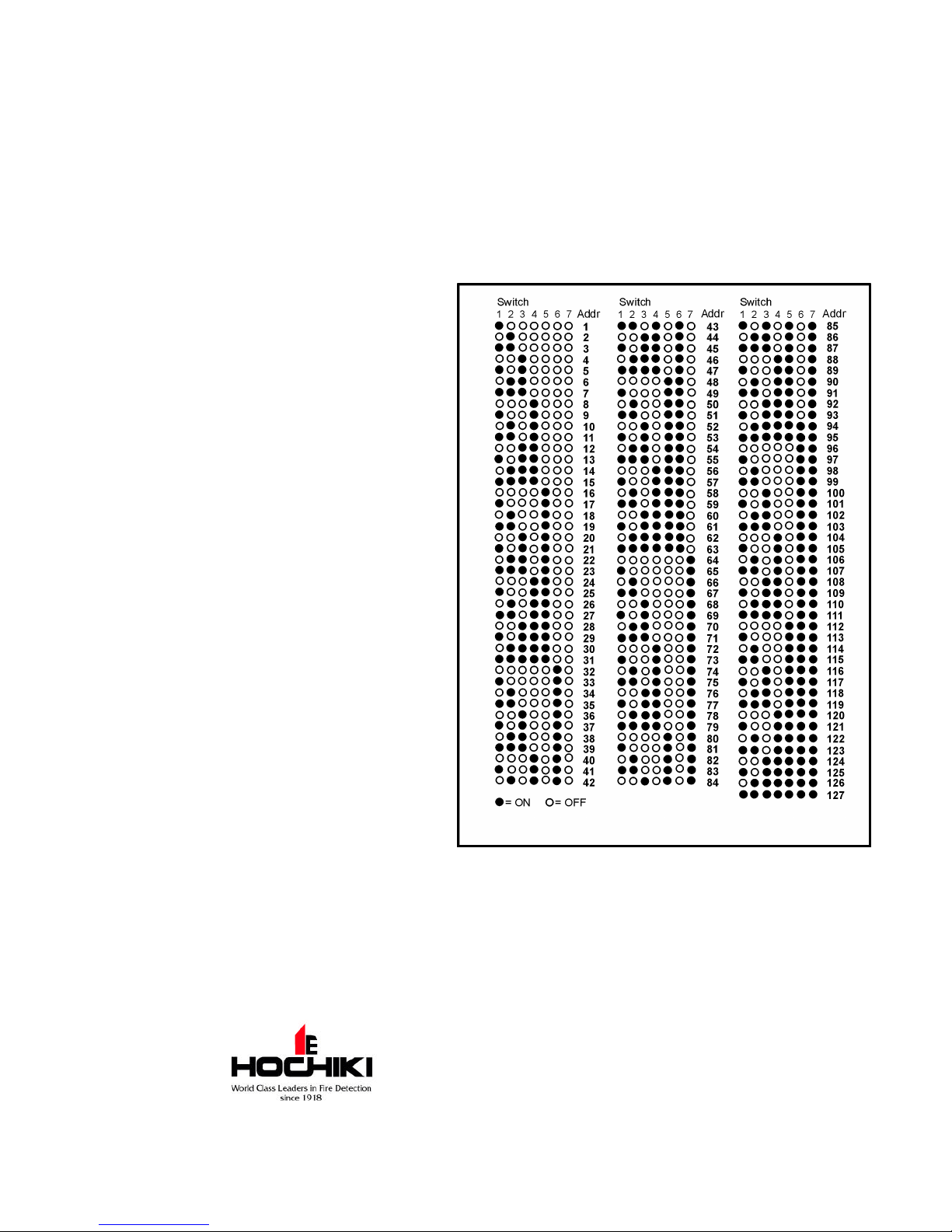
Setting the Loop Address
q The address is set using the first 7 switches of the 8-bit DIL switch. The switch should be in the up position for ON
and down for OFF.
q Set the switches as defined below in Fig 2 for the required address.
Installation
For CHQ-MZ (Enclosure & Module)
q Drill the cable entry holes in the enclosure as
required before fitting the CHQ-MZ/OEM. Ensure
glands conform to IP67, if such ingress protection
is required.
q Mount enclosure as required, using the holes in
the 4 corners which are located through the cover
fixing point.
q Mount the CHQ-MZ/OEM inside the enclosure with
the screws supplied.
q Fix the label to the enclosure and note the unit's
address.
For the CHQ-MZ/DIN
q Clip onto an appropriate DIN Rail, which should be
mounted within an approved enclosure with the
loop connections at the bottom of the unit.
q Write loop address in space provided on door
label.
For both
q Ensure the conventional zone is terminated with
the TE-RH-E (supplied), this must be connected to
the last device on the zone.
q Set the ESP loop address using the 8-bit DIL
switch - see opposite.
q To comply with EMC regulations, these products
must be fitted in a protective enclosure.
q Suitable anti-static precautions must be taken
when handling these products.
Status LED
q A red LED flashes each time the unit is polled by the fire alarm control panel, and continuously illuminated when the
input is active.
Hochiki Europe (UK) Ltd. reserves the right to alter the
specification of its products from time to time without notice.
Although every effort has been made to ensure the accuracy of
the information contained within this document it is not
warranted or represented by Hochiki Europe (UK) Ltd. to be a
complete and up-to-date description. Please check our web
site for the latest version of this document.
Fig 2.
Page 3

2-1-0-024/ISS9/AUG03
Hochiki Europe (UK) Ltd
Grosvenor Road, Gillingham Business Park,
Gillingham, Kent, ME8 0SA, England
Telephone: +44(0)1634 260133 Facsimile: +44(0)1634 260132
Email: sales@hochikieurope.com
Web: www.hochikieurope.com
 Loading...