

Page 1
HOCHIKI INTRINSICALLY SAFE COMPATIBLE SOUNDER CONTROL
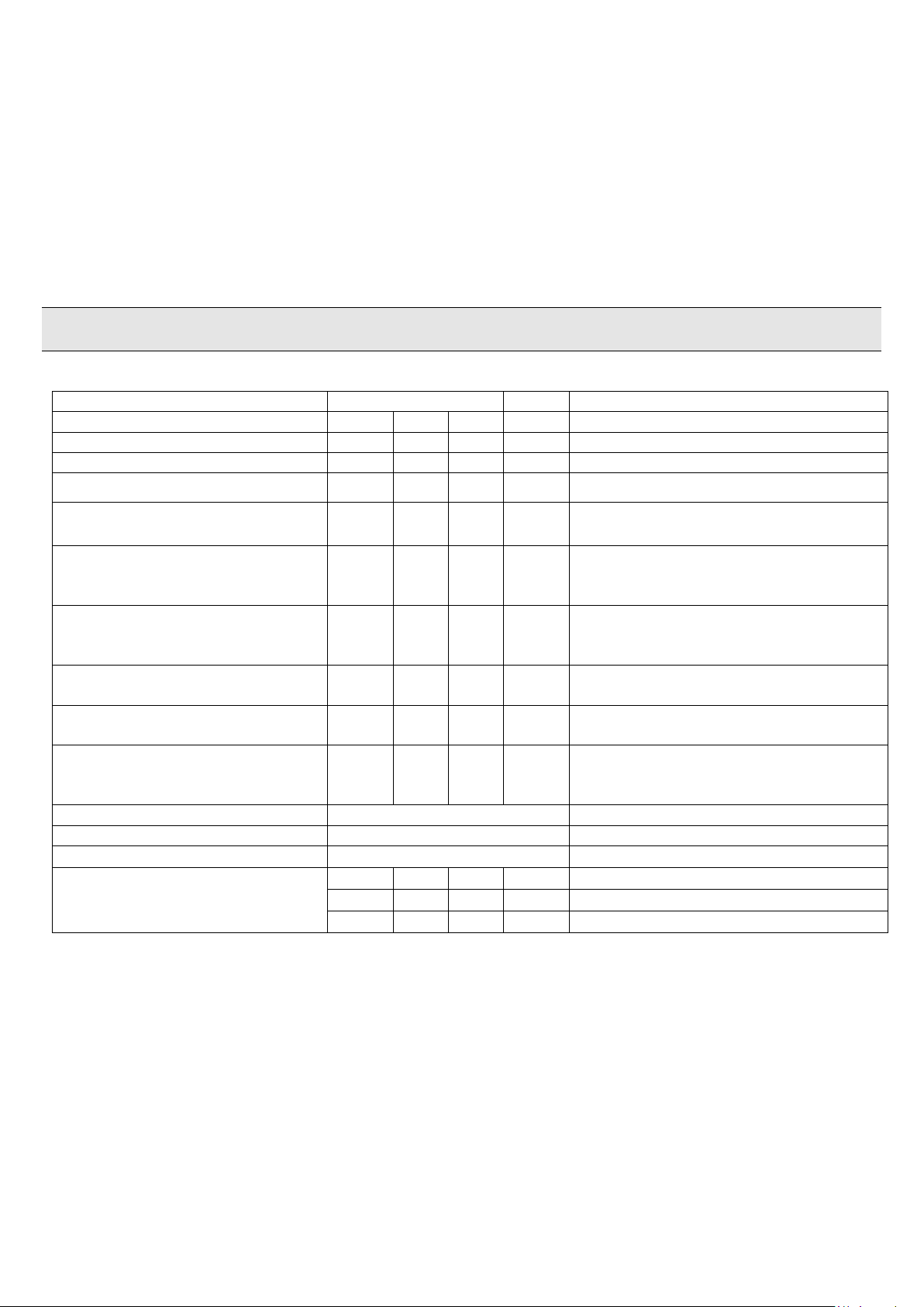
Parameter
Quantity
Units
Notes
Min
Typ.
Max
PSU Supply voltage
20
24
28 V
I.S. BARRIER1 voltage
20 - 28 V
I.S. BARRIER2 voltage
20 - 28 V
Quiescent Current
- - 50
mA
Excluding current drawn by SNDR
EOL’S and IS BARRIER Device loads.
SNDR CCT1 Current powered
with 24V
-
12
15
mA
Does not include current possibly
drawn by SNDR EOL1 (e.g. add 24 mA
if using a 1k EOL resistor)
SNDR CCT2 Current powered
with 24V
12
15
mA
Does not include current possibly
drawn by SNDR EOL2 (e.g. add 24 mA
if using a 1k EOL resistor)
I.S. BARRIER 1 Load current
- - 40
mA
Actual value dependant on IS sounder
used.
I.S. BARRIER 2 Load current
- - 40
mA
Actual value dependant on IS sounder
used.
Maximum Cable Resistance on
I.S. barrier terminals
- - 25
R
This is the combined total Wiring
resistance between the IS Barrier
Terminals and the IS device.
EOL CCT1
User Determined
Hochiki CHQ-DSC module uses a 1K
EOL CCT2
User Determined
Hochiki CHQ-DSC module uses a 1K
Monitored input EOL
10 K resistor
10 K ± 5% 0.4 W
Input Thresholds
9.5
10
10.5
K
Normal condition (10 K)
100
-
-
On/Activated (>100 K
- - 50
On/Activated (<50
MODULE INSTALLATION INSTRUCTIONS
Products covered: CHQ-ISM, CHQ-ISM/DIN and CHQ-ISM(HFP)
Function
The CHQ-ISM is a Sounder Control module which interfaces between the Hochiki Analogue system via a
CHQ-DSC or conventional sounder O/P’s and the intrinsically safe sounder/beacon units via an intrinsically
Safe barrier. The module provides line monitoring for Open or short circuits on the wiring connected to both
the Safe and Hazardous areas. The unit is externally powered with 24V and provides a Fault monitoring I/P
which can be used to indicate something like a mains failure back to the CIE on SNDR CCT1.
NOTE: This sounder interface module should always be used with an I.S. Barrier. The CHQ-ISM is not itself
intrinsically safe.
Specification
Table 1
Hochiki Europe (UK) Limited 2-3-0-1469/ISS1/SEPT13
Page 2
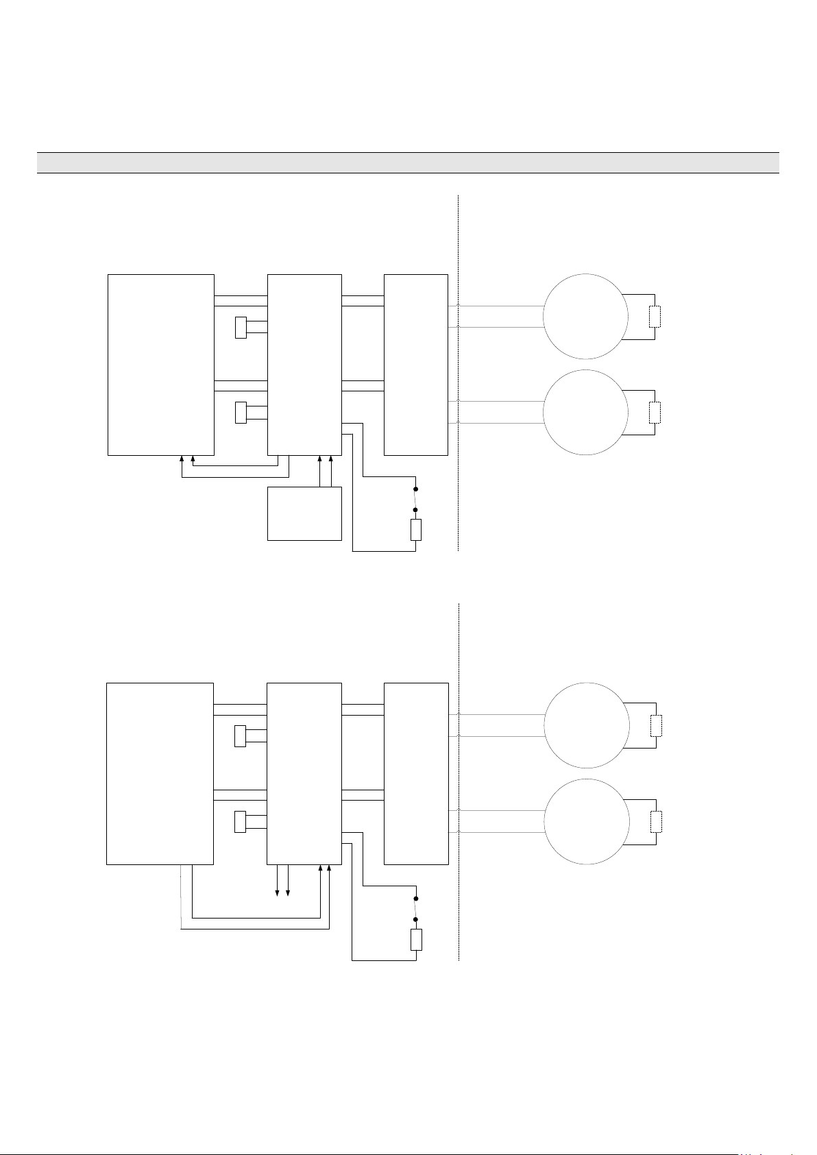
Connection Details
SAFE AREA
EOL
CHQ-DSC or
Sounder Circuit
CH1
Barrier
24V
PSU
CHQ-ISM
+ -
HAZARDOUS AREA
SNDR
CCT1
SNDR
EOL1
SNDR
CCT2
SNDR
EOL2
EOL
+
-
+
-
+
-
CH2
+
-
IS
BARRIER 1
IS
BARRIER 2
24V IN
24V OUT
IS
device
IS
device
Refer to instructions to see if EOL is
required to be fitted.
*
*
*
24V IN
Input
EOL
EOL
EOL
SAFE AREA
EOL
Panel Sounder
Circuits
CH1
Barrier
To other
Equipment
CHQ-ISM
SNDR
CCT1
SNDR
EOL1
SNDR
CCT2
SNDR
EOL2
EOL
+
-
+
-
+
-
CH2
+
-
IS
BARRIER 1
IS
BARRIER 2
24V
OUT
24V IN
IS
device
IS
device
Refer to instructions to see if EOL is
required to be fitted.
*
*
*
24V
AUX
Input
EOL
The CHQ-ISM should be connected as shown in Fig 1 or Fig 2 below, the I.S. device can be either a sounder
or beacon. See Table 3 which shows which I.S. devices have been tested for compatibility with the different
barrier types. Table 3 also shows whether an EOL device is required for compatibility; if required this should
always be placed at the furthest end of the cable, preferably in the terminals of the I.S. device.
NOTE: The CHQ-ISM should always be installed in the safe area along with the barrier.
Fig 1
Hochiki Europe (UK) Limited 2-3-0-1469/ISS1/SEPT13
Fig 2
Page 3

NOTE: For both Fig 1 and 2 a S/C fault on the Barrier terminals will be reported back by the CHQ-DSC or
Galvanic Isolators
Zener Barrier
MTL5561
MTL7787+ (Can only be used with an Isolated 24V supply to power the CHQ-ISM)
KFDO-CS-Ex1.51
KFDO-CS-Ex2.51
KFDO-CS-Ex1.51P
KFDO-CS-Ex2.51P
I.S. Sounder Model
Manufacturer
EOL Required
DB5 sounder
Fulleon
7K5*
IS-MA1
E2S
7K5
IS-MC1
E2S
7k5 (Fitted to sounder terminals only)
IS28 mk5 Banshee
H & B
7K5
IS Beacon Model
Manufacturer
EOL Required
IS-MB1
E2S
7K5 Ŧ
IS Flashdome
Vimpex
7K5 Ŧ*
panel sounder circuits as an O/C fault, it will only be reported as a S/C on the CHQ-ISM status LED’s.
Compatible Barrier types
The CHQ-ISM is capable of supporting the barrier types listed below.
Compatible IS Sounders/Beacon types
NOTE: Only ONE I.S sounder OR I.S beacon can be fitted to each barrier channel otherwise correct fault
monitoring cannot be guaranteed. To ensure correct line fault monitoring only the barriers listed above should
be used with the I.S. devices shown in Table 2
Table 2
Two End of Line resistors (Minimum 230 mm² surface area) are supplied with the unit to be used with the
appropriate I.S. devices as listed in Table 2. Only these EOL resistors should be used and not substituted
with any equivalent values or types.
* Removing just the EOL will not necessarily generate an O/C fault, this can only be guaranteed by creating an
actual O/C on the line effectively removing the device and EOL.
Ŧ Due to the capacitive nature of the beacon if an EOL test is carried out by removing it, an O/C fault may take
up to one minute to be indicated.
NOTE: When one of the I.S. Barrier circuits is not used, it should be fitted with one of the supplied 7K5 EOL
resistors directly into the CHQ-ISM terminals to prevent an O/C fault from being indicated on the status LED’s.
Hochiki Europe (UK) Limited 2-3-0-1469/ISS1/SEPT13
Page 4

Installation – “Smart-Fix” with Back Box
CHQ-ISM
CHQ-ISM(HFP)
0832-CPR-F0060/13
13
EN54-18 Input/Output Modules
CHQ-ISM/DIN
0832-CPR-F0061/13
13
EN54-18 Input/Output Modules
Hochiki Europe (UK) Ltd
Grosvenor Road, Gillingham Business Park,
Gillingham, Kent, ME8 0SA, England
Telephone: +44(0)1634 260133
Facsimile: +44(0)1634 260132
Email: sales@hochikieurope.com
Web: www.hochikieurope.com
Hochiki Europe (UK) Ltd. reserves the right to
alter the specification of its products from time to
time without notice. Although every effort has
been made to ensure the accuracy of the
information contained within this document it is
not warranted or represented by Hochiki Europe
(UK) Ltd. to be a complete and up-to-date
description. Please check our web site for the
latest version of this document.
For those installations requiring glanded cables, a module back box (CHQ-BACKBOX) is available (sold
separately).
This features ten knock-out cable entries (glands are not supplied). Ensure glands used conform to IP67, if
such ingress protection is required. The CHQ-BACKBOX is mounted on the fixing surface; the CHQ Module is
then fitted to the top of the back box. Finally the CHQ-LID is added creating a sealed enclosure. For further
details refer to the CHQ-BACKBOX Instructions (2-3-0-800).
Installation – DIN Version
DIN modules should be mounted in a suitable enclosure in conjunction with an NS 35 mounting rail
with the loop connections at the bottom of the unit. Hochiki recommends the SMB-2 and SMB-3 boxes
designed specifically for this purpose.
Terminate and connect field wiring.
Suitable anti-static precautions must be taken when handling these products.
Status LEDs
Green LED “PSU” ON solid, used to indicate healthy PSU.
Green LED “PSU” OFF, used to indicate no power or low power.
Yellow LED “Bar1 O/C” ON flashing, used to indicate fault on I/P.
Yellow LED “Bar1 S/C” ON solid, used to indicate IS Barrier 1 has an S/C.
Yellow LED “Bar1 O/C” ON solid, used to indicate IS Barrier 1 has an O/C.
Yellow LED “Bar2 S/C” ON solid, used to indicate IS Barrier 2 has an S/C.
Yellow LED “Bar2 O/C” ON solid, used to indicate IS Barrier 2 has an O/C.
* For Declarations of Performance visit www.hochikieurope.com
Hochiki Europe (UK) Limited 2-3-0-1469/ISS1/SEPT13
 Loading...