

Page 1
HOCHIKI INTRINSICALLY SAFE COMPATIBLE DUAL ZONE
MONITOR INSTALLATION INSTRUCTIONS
Products covered: CHQ-DZM(SCI)-IS, CHQ-DZM/DIN(SCI)-IS
Function
The CHQ-DZM(SCI)-IS is an input monitoring device which connects to the Hochiki ESP analogue system. It is capable
of monitoring two zones of intrinsically safe detectors through an intrinsically safe barrier. The unit also pro vides two
controllable outputs, which can be used to drive remote LEDs (if supported by the Control Panel). The unit is available as
either a “Smart-Fix” module box or as a DIN Rail mountable unit with both variants featuring an integral short-circuit
isolator.
Specification
Order codes CHQ-DZM(SCI)-IS and CHQ-DZM/DIN(SCI)-IS*
Transmission method Digital communication using ESP
Operating voltage 17 – 41 VDC
Quiescent current 330 µA
Loop
External
supply
Output rating 24 VDC 8.5 mA
Zone loading (max) Up to 20 SLR-E-IS or DCD-1E-IS detectors (or a mixture of
E.O.L device (see note below)
Zone resistance
Zone capacitance 0.3 µF (Max)
Colour and enclosure material
* Fire alarm control panel compatibility required for these products. See AP0127 for short-circuit isolator specifications.
NOTE: The EOL resistors supplied with the CHQ-DZM(SCI)-IS comply with Hochiki’s BASEEFA certification for
conventional I.S. detectors. The user must check that any EOL resistors used comply with the certification requirements
for the proposed installation.
Current consumption whilst polling 22 mA ± 20 %
Isolator leakage current (switch open) 8 mA (max)
Isolator switch current (switch closed) 1 A (max)
Operating voltage 20-28.8 VDC (24 VDC nominal)
Current consumption when in fire 70 mA (Both zones in fire)
both), Up to 20 CCP-E-IS manual call points
10 k
resistor
50
(Max)
CHQ Module & CHQ-BACKBOX White ABS
DIN Module Green ABS
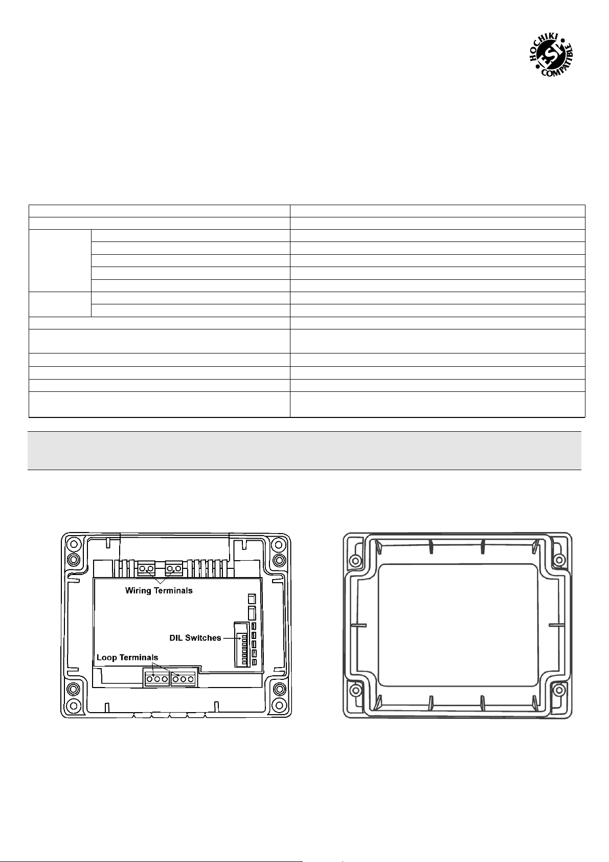
Components
Standard "Smart-Fix" Modules are supplied as two individual components (see Fig 1 & 2). DIN versions are supplied as one unit
(see Fig 3).
Fig 1
"Smart-Fix" CHQ Module (Back Plate inc PCB Component)
(Note: configuration of Wiring Terminal blocks differs between
models)
CHQ-LID Transparent Module Lid
(Supplied with four screws and acrylic retaining washers)
Fig 2
Hochiki Europe (UK) Limited 2-3-0-1366/ISS3/DEC11
Page 2
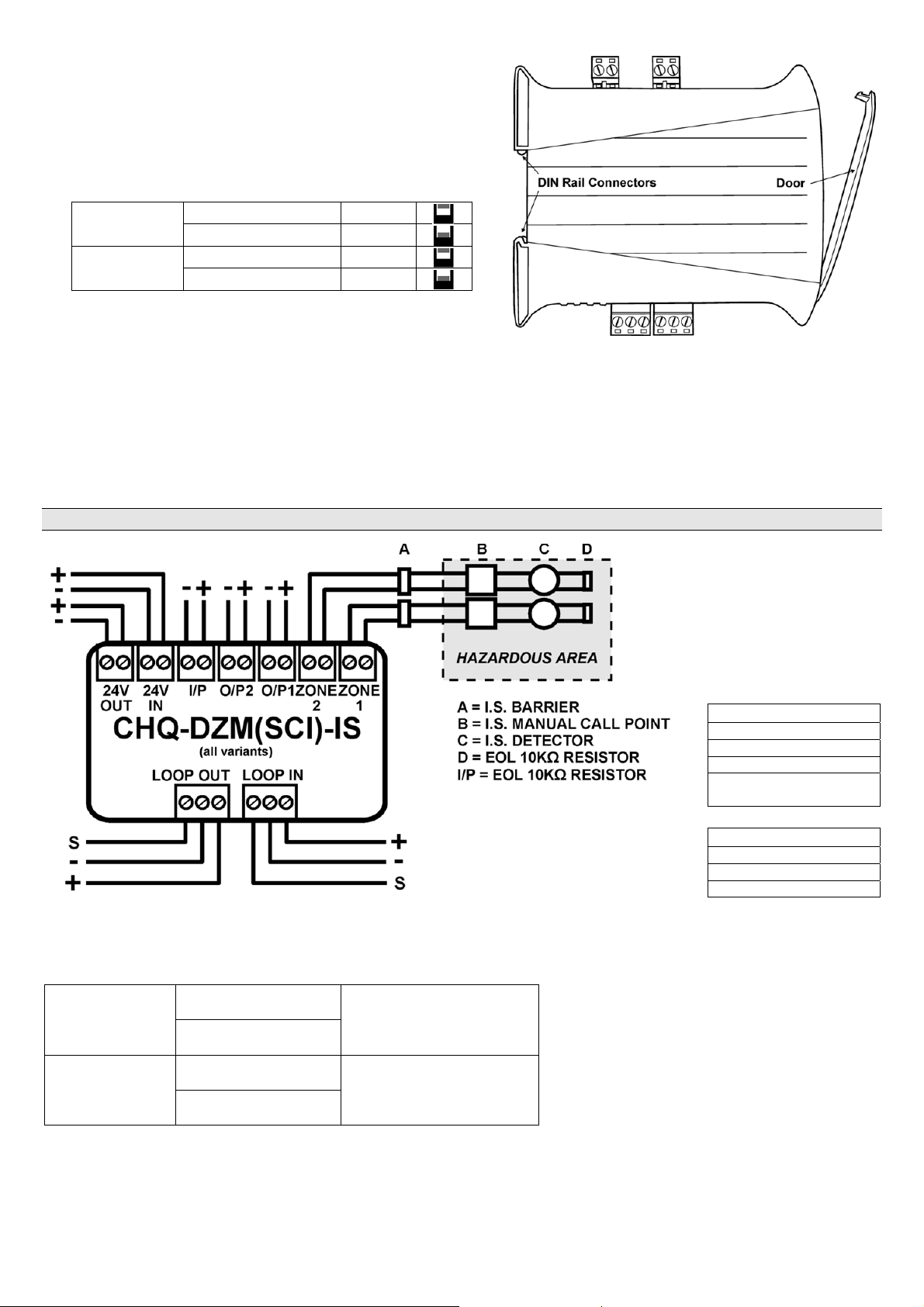
Setting the Loop Address
The analogue address of the Module is set using the first 7
switches of the 8-bit DIL switch, which in the case of the
Standard CHQ is located through the cut-out section on the
top of the PCB cover. On the DIN version, this switch is
located on the edge of the PCB behind the clear door (see
Fig 3).
The switches are numbered 1 to 8 (left to right):
CHQ
MODULE
DIN
MODULE
The switches should be set using a small-tipped screwdriver
SWITCH UP ON
SWITCH DOWN OFF
SWITCH UP OFF
SWITCH DOWN ON
or similar.
Refer to the Address Chart (Fig 5) on page 3 for a quick
reference on addresses.
Fig 3
DIN Rail Mountable CHQ Module
Connection Details
The CHQ-DZM(SCI)-IS should be connected to the loop as shown below, the module does not support any line contin uity
options, therefore, if manual Call Points are to be interfaced to the unit then these should be connected first. Detectors
should be connected to the CHQ-DZM(SCI)-IS in accordance with Hochiki’s I.S. certification.
NOTE: The CHQ-DZM(SCI)-IS must be installed in the safe area along with the barrier.
Compatible Barrier
Types
The CHQ-DZM(SCI)-IS
and CHQ-DZM/DIN(SCI)IS are capable of
supporting the barrier
types listed below.
Galvanic Isolators
MTL5561
KFD0-CS-Ex1.51P
KFD0-CS-Ex2.51P
MTL5061 & MTL4061
Fig 4
(older types)
Zener Barriers
MTL7728+
MTL7787+
MTL728+ (older type)
Setting EOL Monitoring Option
Select the required EOL monitoring option using the 2-bit DIL switch.
SWITCH 1 DOWN
CHQ MODULE
I.S. MODE*
SWITCH 2 UP
SWITCH 1 UP
DIN MODULE
I.S. MODE*
SWITCH 2 DOWN
* Fire alarm control panel compatibility required for these products.
Hochiki Europe (UK) Limited 2-3-0-1366/ISS3/DEC11
Page 3

Installation – "Smart-Fix" Version
Set analogue address before installation (see previous page). The
fixing surface should be dry and stable.
Hold the back plate up against the fixing surface and mark the
position of the four corner fixing holes.
Determine which cut-out sections along the top and bottom edges
of the module require removing to accommodate the cables being
used.
Remove cut-outs by scoring with a sharp knife before breaking off
with pliers or snips.
Mount the back plate using appropriate fixings (not supplied) for the
fixing surface.
Terminate and connect field wiring as per the wiring diagram on
pages 2 (and the terminal block indications on the product label).
The transparent lid (CHQ-LID) is supplied with four screws and eight
retaining washers.
Push the screws through one of the retaining washers and then
through the holes in the lid from front to back, pushing another
retaining washer onto the end inside the lid.
Screw the lid onto the back plate; do not over tighten the screws as
this could damage the unit.
Note, a white plastic version of the lid is available (sold separately –
CHQ-LID(WHT)).
Fig 5
Installation with Back Box
For installations requiring glanded cables, a module back box (CHQ-BACKBOX) is available (sold separately). This is
mounted on the fixing surface; the CHQ Module is then fitted to the top of the back box and the CHQ-LID is added
creating a sealed enclosure. For further details refer to the CHQ-BACKBOX Instructions (2-3-0-800). For i nstallations
utilising heavy-duty cabling (for example, 1.5mm
plate and CHQ-ADAPTOR is recommended.
2
solid conductor) the use of the SMB-1 Box with the SMB-ADAPTOR
For further details refer to the SMB-ADAPTOR Instructions (2-3-0-1502).
Ensure any glands used (not supplied) conform to IP67, if such ingress protection is required.
Installation – DIN Version
Set loop address before installation (see page 2) and write loop address in space provided on door label.
DIN modules should be mounted in a suitable enclosure in conjunction with an NS 35 mounting rail with the loop connections
at the bottom of the unit. Hochiki recommends the SMB-2 and SMB-3 Boxes designed specifically for this purpose.
Terminate and connect field wiring as per the wiring diagram on page 2 (and the terminal block indications on the product
label).
Suitable anti-static precautions must be taken when handling these products.
Status LEDs
CHQ-DZM(IS)
(all variants)
Intrinsically Safe
Dual Zone Monitor
Green LED flashes each time the unit is polled by the fire alarm control panel. Amber
LED is continually illuminated when unit detects short-circuit fault.
Protocol
specified
in TI/006
CHQ-DZM(SCI)-IS 0832-CPD-1659 11
CHQ-DZM/DIN(SCI)-IS 0832-CPD-1660 11
EN54-17 Short Circuit Isolators
EN54-18 Input/Output Modules
Hochiki Europe (UK) Ltd
Grosvenor Road, Gillingham Business Park,
Gillingham, Kent, ME8 0SA, England
Telephone: +44(0)1634 260133
Facsimile: +44(0)1634 260132
Email: sales@hochikieurope.com
Web: www.hochikieurope.com
Hochiki Europe (UK) Ltd. reserves the right to alter the
specification of its products from time to time without notice.
Although every effort has been made to ensure the accuracy
of the information contained within this document it is not
warranted or represented by Hochiki Europe (UK) Ltd. to be a
complete and up-to-date description. Please check our web
site for the latest version of this document.
Hochiki Europe (UK) Limited 2-3-0-1366/ISS3/DEC11
 Loading...