

Page 1
Hochiki Europe (UK) Ltd
Mains Relay Controller
Dual Sounder Controller
Dual Relay Controller
CHQ-MRC2(SCI)
CHQ-MRC2/DIN(SCI)
CHQ-DSC(SCI)
CHQ-DSC/M(SCI)
CHQ-DSC/DIN(SCI)
CHQ-DRC2(SCI)
CHQ-DRC2/DIN(SCI)
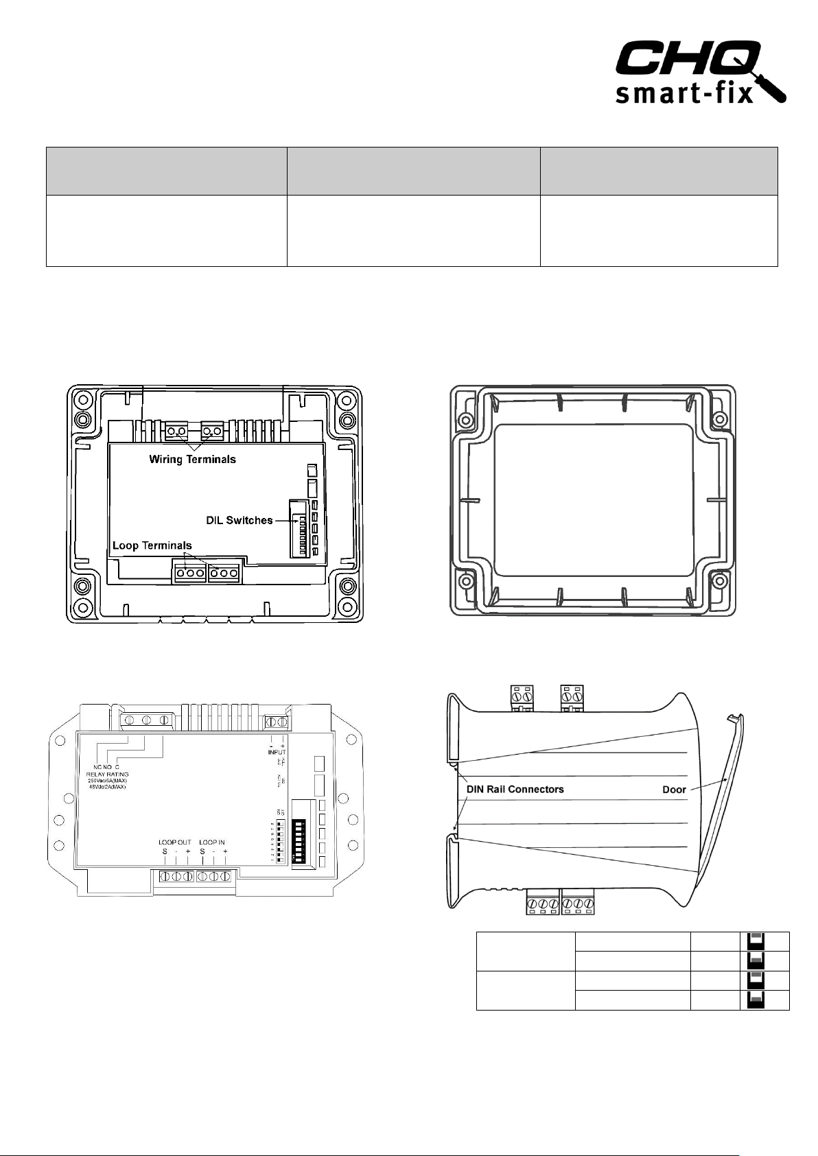
Fig 1
Fig 2
"Smart-Fix" CHQ Module (Back Plate inc PCB Component)
(Note: configuration of Wiring Terminal blocks differs between
models)
CHQ-LID Transparent Module Lid
(Supplied with four screws and acrylic retaining
washers)
Fig 3
Fig 4
Mains Relay Controller Adaptor Plate
DIN Rail Mountable CHQ
Setting the Loop Address
The analogue address of the Module is set using the first 7
switches of the 8-bit DIL switch, which in the case of the
Standard CHQ is located through the cut-out section on the top
of the PCB cover. On the DIN version, this switch is located on
the edge of the PCB behind the clear door (see Fig 4).
The switches are numbered 1 to 8 (left to right):
CHQ MODULE
SWITCH UP
ON
SWITCH DOWN
OFF
DIN MODULE
SWITCH UP
OFF
SWITCH DOWN
ON
The switches should be set using a small-tipped screwdriver or similar.
Refer to the Address Chart (Fig 7) on page 5 for a quick reference on addresses. (contd on page 4)
CHQ MODULES INSTALLATION INSTRUCTIONS
Products Covered: CHQ-DSC (Dual Sounder Controller), CHQ-DRC2 (Dual Relay Controller) &
CHQ-MRC2 (Mains Relay Controller)
Introduction
The CHQ "Smart-Fix" Range of Modules consists of the following models:
Note: (SCI) indicates all modules feature an integral short-circuit isolator. DIN indicates Module housing is designed to fit
standard “Top Hat” DIN Rail.
Components
Standard "Smart-Fix" Modules are supplied as two individual components (see Fig 1 & 2). DIN versions are supplied as
one unit (see Fig 4).
Page 1 2-3-0-1730/ISS3/DEC13
Page 2
Hochiki Europe (UK) Ltd
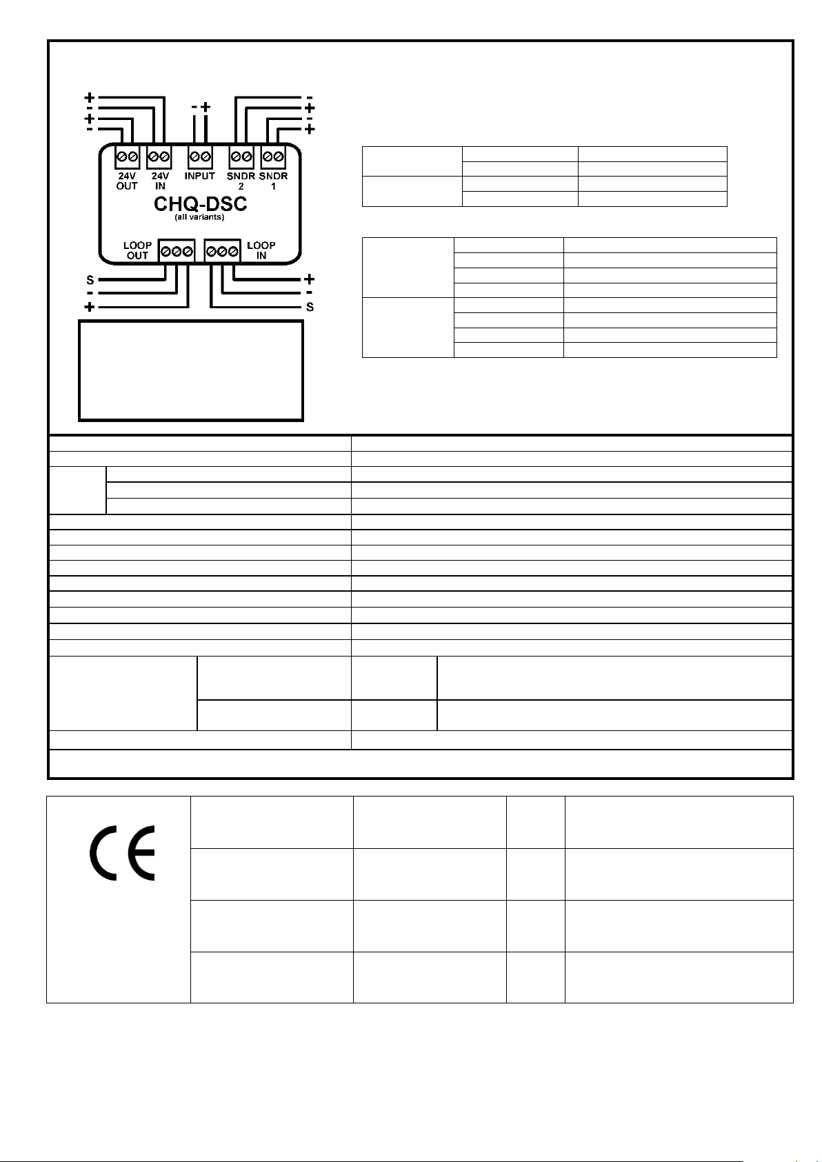
CHQ-DSC DUAL SOUNDER CONTROLLER provides two independent sounder outputs with open and short circuit monitoring (which
can be disabled). The sounder outputs can be separately driven, continuously or pulsed, under full synchronisation of the fire alarm
panel with other sounders on the same loop. An input is provided with short and open circuit monitoring (which can be disabled).
Setting Sounder & Input Monitoring
8-Way DIL Switch
CHQ MODULE
SWITCH 8 UP
I/P Monitoring Disabled
SWITCH 8 DOWN
I/P Monitoring Enabled
DIN MODULE
SWITCH 8 UP
I/P Monitoring Enabled
SWITCH 8 DOWN
I/P Monitoring Disabled
2-Way DIL Switch
CHQ MODULE
SWITCH 1 UP
SNDR O/P 1 Monitoring Disabled
SWITCH 1 DOWN
SNDR O/P 1 Monitoring Enabled
SWITCH 2 UP
SNDR O/P 2 Monitoring Disabled
SWITCH 2 DOWN
SNDR O/P 2 Monitoring Enabled
DIN MODULE
SWITCH 1 UP
SNDR O/P 1 Monitoring Enabled
SWITCH 1 DOWN
SNDR O/P 1 Monitoring Disabled
SWITCH 2 UP
SNDR O/P 2 Monitoring Enabled
SWITCH 2 DOWN
SNDR O/P 2 Monitoring Disabled
This module requires an auxiliary 24 Vdc power supply (this can also be
monitored) - see Fig 4.
Order codes
CHQ-DSC(SCI) / CHQ-DSC/M(SCI) / CHQ-DSC/DIN(SCI)*1
Transmission method
Digital communications using ESP
Loop:
Operating voltage
17 - 41 Vdc
Quiescent current
290 A
Current consumption whilst polling
22 mA 20 %
Current in short-circuit
8 mA
Maximum short-circuit current (Loop)
1 A
External Supply:-Operating voltage
20-28.8 Vdc (24 Vdc nominal)
Current consumption (per line)
Sounder On - 8 mA, Sounder Fault - 6 mA
Sounder output current
1 A/line max
Sounder line capacitance
0.3 F/line max.
Sounder E.O.L resistor
1 k, 5%, 2 W
Input E.O.L resistor
10 k, 5%, 0.25 W
Input threshold levels
ON=470 , short cct< 50 , open cct>100 k,
Weights (g) &
Dimensions (mm)
CHQ-DSC(SCI)
360
L=157 x W=127 x D=35 (CHQ Module plus Lid)
D=79 (CHQ Module plus Lid plus CHQ-BACKBOX)
(add 235 to module weight when using CHQ-BACKBOX)
CHQ-DSC/DIN(SCI)
145
L=119 x W=108 x D=24
Colour and enclosure material
CHQ Module & CHQ-BACKBOX White ABS, DIN Module Green ABS
*1 Fire alarm control panel compatibility required for these products. See AP0127 for short circuit isolator specifications.
Note:- All EOL and operational resistors are supplied with the unit – DO NOT DISCARD IN ERROR!
Protocol specified in
TI/006
CHQ-DSC/(SCI)
CHQ-DSC(HFP)-SCI
0832-CPD-1102*1
09
EN54-17 Short Circuit Isolators
EN54-18 Input/Output Modules
CHQ-DSC/DIN(SCI)
0832-CPD-1103*1
10
EN54-17 Short Circuit Isolators
EN54-18 Input/Output Modules
CHQ-MRC2(SCI)
CHQ-MRC2(HFP)-SCI
0832-CPR-F0058/13*1
13
EN54-17 Short Circuit Isolators
EN54-18 Input/Output Modules
CHQ-MRC2/DIN(SCI)
0832-CPR-F0059/13*1
13
EN54-17 Short Circuit Isolators
EN54-18 Input/Output Modules
Fig 4
LOOP CONNECTIONS
S = Cable Screen (if required)
- = Loop Negative (-ve)
+ = Loop Positive (+ve)
*1
For Declarations of Performance visit www.hochikieurope.com
Page 2 2-3-0-1730/ISS3/DEC13
Page 3

Hochiki Europe (UK) Ltd
CHQ-DRC2 DUAL RELAY CONTROLLER is a loop powered input/output module with two independent N/O and N/C volt free
change over relay outputs which can be driven separately. Used for the control of devices such as dampers or for plant and
equipment shutdown. A single input is also provided for local fire and fault monitoring which is fully monitored for open and short
circuit (can be disabled).
Setting Fault Monitoring
8-Way DIL Switch
CHQ MODULE
SWITCH 8 UP
Monitoring Disabled
SWITCH 8 DOWN
Monitoring Enabled
DIN MODULE
SWITCH 8 UP
Monitoring Enabled
SWITCH 8 DOWN
Monitoring Disabled
Note:- The state of the relay contacts will be indeterminate until the
unit is powered.
Order codes
CHQ-DRC2(SCI) / CHQ-DRC2/DIN(SCI)*
Transmission method
Digital communication using ESP
Loop:
Operating voltage
17 - 41 Vdc
Quiescent current
300 A
Current consumption whilst polling
22 mA 20 %
Current in short-circuit
8 mA
Maximum short-circuit current (Loop)
1 A
Relay contact rating
30 Vdc max, 1 A (resistive load)
Input E.O.L resistor
10 k, 5%, 0.25 W
Input threshold level
ON=470 , Short cct <50 , Open cct >100 k
Weights (g) and
Dimensions (mm):
CHQ-DRC2(SCI)
346
L=157 x W=127 x D=35 (CHQ Module plus Lid)
D=79 (CHQ Module plus Lid plus CHQ-BACKBOX)
(add 235 to module weight when using CHQ-BACKBOX)
CHQ-DRC2/DIN(SCI)
124
L=119 x W=108 x D=24
Colour and enclosure material
CHQ Module & CHQ-BACKBOX White ABS, DIN Module Green ABS
*1 Fire alarm control panel compatibility required for these products. See AP0127 for short circuit isolator specifications.
Note:- All EOL and operational resistors are supplied with the unit – DO NOT DISCARD IN ERROR!
CHQ-MRC2 MAINS RELAY CONTROLLER is a loop powered input/output module, with a single mains-rated change-over relay
output, which has the N/O, N/C and COMMON contacts available via screw terminal contacts. This output is driven under the control
of the fire alarm panel and can be used for the control of devices such as dampers or for plant and equipment shutdown. A single
input is also provided for local fire and fault monitoring and this is fully monitored for open and short circuit (can be disabled). Note:The state of the relay contacts will be indeterminate until the unit is powered.
Setting Input Monitoring
8-Way DIL Switch
CHQ MODULE
SWITCH 8 UP
Monitoring Disabled
SWITCH 8 DOWN
Monitoring Enabled
DIN MODULE
SWITCH 8 UP
Monitoring Enabled
SWITCH 8 DOWN
Monitoring Disabled
Order codes
CHQ-MRC2(SCI) / CHQ-MRC2/DIN(SCI)*
Transmission method
Digital communication using ESP
Loop:
Operating voltage
17 - 41 Vdc
Quiescent current
300 A
Current consumption whilst polling
22 mA 20 %
Relay contact rating**
48 Vdc max, 2 A (resistive load), 250 Vac max, 5 A (resistive load) – For mains AC switching,
the Control Panel must be compliant with Low Voltage Directive for SELV circuits.
Input E.O.L resistor
10 k, 5%, 0.25 W
Input threshold level
ON=470 , Short cct <50 , Open cct >100 k
Weights (g)
and
Dimensions
(mm)
CHQ-MRC2(SCI)
133
L=190 x W=90 x D=25
CHQ-MRC2/DIN(SCI)
121
L=119 x W=108 x D=24
Colour and enclosure material
Adaptor Plate and PCB cover white ABS and Polycarbonate, DIN Module Green ABS
To ensure compliance with EN54-17:2005 and EN54-18:2005 is maintained the CHQ-MRC2(SCI) & CHQ-MRC2/DIN(SCI) must be installed within an enclosure weighing greater than 4.75kg. The
enclosure should have an ingress protection rating of IP65 or greater.
*1 Fire alarm control panel compatibility required for these products. See AP0127 for short circuit isolator specifications.
Note:- All EOL and operational resistors are supplied with the unit – DO NOT DISCARD IN ERROR!
Fig 6
Fig 5
CHQ-MRC2
(all variants)
** No fuses are fitted on this device. The relay output circuit must
therefore be protected by a suitable over-current protection device to
prevent excessive current through the relay contacts. Refer to the relay
contact specification in this document.
Page 3 2-3-0-1730/ISS3/DEC13
Page 4

Hochiki Europe (UK) Ltd
Installation – "Smart-Fix" Version
Set analogue address before installation (see page 2).
The fixing surface should be dry and stable.
Hold the back plate up against the fixing surface and
mark the position of the four corner fixing holes.
Determine which cut-out sections along the top and
bottom edges of the module require removing to
accommodate the cables being used.
Remove cut-outs by scoring with a sharp knife before
breaking off with pliers or snips.
Mount the back plate using appropriate fixings (not
supplied) for the fixing surface.
Terminate and connect field wiring as per the wiring
diagrams on pages 2 & 3 (and the terminal block
indications on the product label).
The transparent lid (CHQ-LID) is supplied with four screws
and eight retaining washers.
Push the screws through one of the retaining washers
and then through the holes in the lid from front to back,
pushing another retaining washer onto the end inside
the lid.
Screw the lid onto the back plate; do not over tighten
the screws as this could damage the unit.
Fig 7
NOTE: A white plastic version of the lid is available (sold
separately – CHQ-LID(WHT)).
Installation – "Smart-Fix" with Back Box
For those installations requiring glanded cables, a module back box (CHQ-BACKBOX) is available (sold separately).
This features ten knock-out cable entries (glands are not supplied). Ensure glands used conform to IP67, if such ingress
protection is required. The CHQ-BACKBOX is mounted on the fixing surface; the CHQ Module is then fitted to the top of
the back box. Finally the CHQ-LID is added creating a sealed enclosure. For further details refer to the CHQ-BACKBOX
Instructions (2-3-0-800).
CHQ-DRC2 (all variants)
Dual Relay Controller
Green LED flashes each time the unit is polled by the
fire alarm control panel.
Amber LED is continually illuminated when unit
detects short-circuit fault.
CHQ-MRC2 (all variants)
Mains Relay Controller
CHQ-DSC (all variants)
Dual Sounder Controller
Green LED flashes each time the unit is polled by the
fire alarm control panel and a red LED is continuously
illuminated when either output is active.
Amber LED is continually illuminated when unit
detects short-circuit fault.
Hochiki Europe (UK) Ltd
Grosvenor Road, Gillingham Business Park,
Gillingham, Kent, ME8 0SA, England
Telephone: +44(0)1634 260133
Facsimile: +44(0)1634 260132
Email: sales@hochikieurope.com
Web: www.hochikieurope.com
Hochiki Europe (UK) Ltd. reserves the right to alter
the specification of its products from time to time
without notice. Although every effort has been made
to ensure the accuracy of the information contained
within this document it is not warranted or
represented by Hochiki Europe (UK) Ltd. to be a
complete and up-to-date description. Please check
our web site for the latest version of this document.
Installation – DIN Version
Set analogue address before installation (see page 1) and write loop address in space provided on door label.
DIN modules should be mounted in a suitable enclosure in conjunction with an NS 35 mounting rail with the loop
connections at the bottom of the unit. Hochiki recommends the SMB-2 and SMB-3 Boxes designed specifically for this
purpose.
Terminate and connect field wiring as per the wiring diagrams on pages 2 & 3 (and the terminal block indications on
the product label).
Suitable anti-static precautions must be taken when handling these products.
Status LEDs
Refer to the following table for Status LED indications:
Page 4 2-3-0-1730/ISS3/DEC13
 Loading...