

Page 1
Well Cap Installation Instructions (WELL-CAP-02)
For use with a HOBO® MicroRX Water Level Station (RX2103 or RX2104) or Water Level Sensor Module (RXMOD-W1)
Before you Begin
Follow these instructions before deploying the water level sensor with a station or in a well. If the
sensor has already been installed in a well, remove it before continuing.
Attaching the Well Cap to a Well
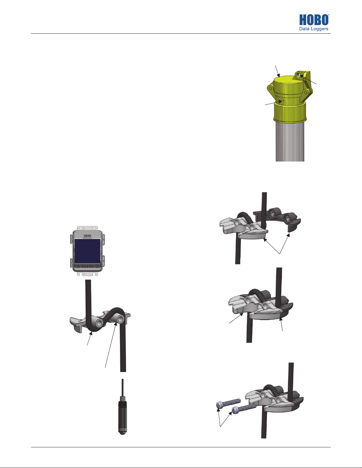
This cap can be installed on a standard 5 cm (2 inch) pipe, metal or PVC, without glue as shown
at right. It also fits on most threaded 5 cm (2 inch) pipes. If the cap is too loose once installed on
a threaded pipe, add a small piece of connector pipe that has both a threaded end and a smooth
end. Attach the threaded end of the connector pipe to the threaded end of the original pipe,
leaving the smooth end of the connector pipe at the top to attach the well cap. As an alternative
to a connector pipe, you can add duct tape around the threaded portion so that the cap is snug
when placed on the pipe.
Place the closed well cap on the end of the well. Use a hammer or mallet to tap the well cap firmly
in place. Attach a padlock to the latch if desired.
Installing the Water Level Sensor in the Well Cap
1. Using the half of the disk with posts, thread the water level
sensor cable under one post and over the other post as
shown below. The station and sensor are shown as reference
for proper cable routing around the posts. Adjust the
positioning of the cable as necessary to ensure there is
enough length to reach the mounted station outside the well
while deploying the sensor to the desired depth inside the
well.
2. Insert the posts (with the cable routed as shown) into the
receptacles in the other half, forming one disk when
connected.
Use a hammer on top
of closed well cap to
tap it firmly in place
Vent hole,
0.318 cm
(0.125 in)
Optional:
attach a
padlock here,
hole diameter
is 1.02 cm
(0.4 inch)
Thread the water
level sensor cable
under one post
And then
over the
other post
(RX2104 station
shown as an example)
Connect the
Opening for use
with water level
meter
two halves
Two halves connected
with proper cable routing
3. Insert the two screws through the posts and use a Phillipshead screwdriver to screw them into place.
23988-B MAN-WELL-CAP-02
Install the screws
Page 2
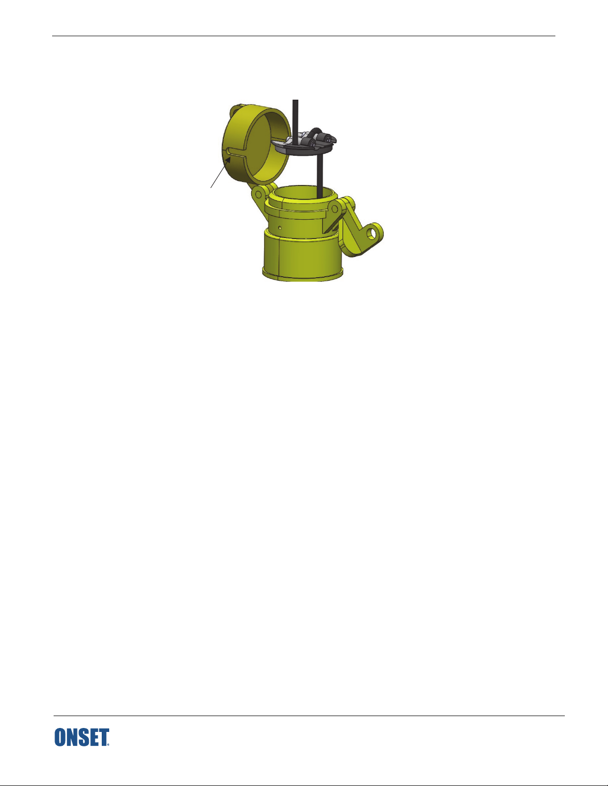
4. Place the disk with the sensor attached into the well cap. Route the other end of the cable through the hole on the side of the well cap
lid. When the well cap is open, use the opening in the disk (shown in step 2) to take a reference water level measurement with a water
level meter while the sensor is in position.
Route the cable
through this hole
and up to the
station
5. Close the well cap. Use a padlock to restrict access to the well if desired.
1-800-LOGGERS (564-4377) • 508-759-9500
www.onsetcomp.com/support/contact
© 2019 Onset Computer Corporation. All rights reserved. Onset and HOBO are registered trademarks of Onset
Computer Corporation. All other trademarks are the property of their respective companies.
23988-B MAN-WELL-CAP-02
 Loading...