

Hobo S-WCG-M003 User Manual
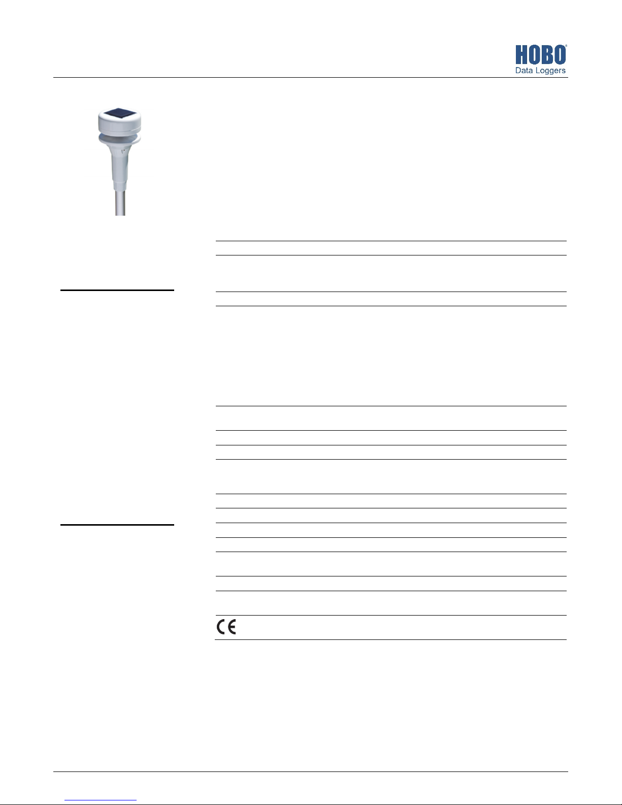
Ultrasonic Wind Speed and Direction Smart Sensor
W
(S-WCG-M003) Manual
The Ultrasonic Wind Speed and Direction smart sensor is designed to work with HOBO®
stations and is powered by its own built-in solar panel. The smart sensor has a plug-in modular
connector that allows it to be added easily to a HOBO station. All sensor parameters are stored
inside the smart sensor, which automatically communicates configuration information to the
logger without the need for any programming or extensive setup. Note: This sensor has been
modified to work with Onset station loggers only.
Specifications
Wind Speed/Gust Wind Direction
Measurement Range 0 to 41.16 m/s (0 to 92.07 mph) 0 to 359 degrees
Ultrasonic Wind Speed &
Direction Smart Sensor
S-WCG-M003
Items included:
• North alignment tool
• U-bolts with hex nuts,
brackets, spacers, and lock
nuts for mounting on a
mast or cross arm
Items required:
• Phillips-head screw driver
• 10 mm wrench (if
mounting on a mast or
cross arm)
• Screws and drill (if
mounting on a vertical
surface)
Accessories:
• Grounding kit (M-GKA)
Accuracy ±0.8 m/s (1.79 mph) or ±4% of
Resolution 0.4 m/s (0.89 mph) 1 degrees (0 to 359 degrees)
Measurement Definition Wind speed readings are taken
Operating Temperature Range
Without Icing
Environmental Rating Weatherproof
Housing Polyacetal
Dimensions Sensor length: 380 mm (14.96 inches)
eight 200 g (7 oz)
Power Supply Photovoltaic panel, LIFEP04 3.2 V -600 mAh battery
Bits per Sample 8 for each channel, 24 total
Number of Data Channels* 3
Measurement Averaging
Option
Cable Length Available 3 m (9.8 ft)
Length of Smart Sensor
Network Cable*
* A single HOBO station can accommodate 15 data channels and up to 100 m (328 ft) of smart sensor cable (the digital
communications portion of the sensor cables).
reading, whichever is greater
every three seconds for the
duration of the logging interval
Wind speed: Average speed for
the entire logging interval
Gust speed: The highest threesecond wind recorded during
the logging interval
See Measurement Operation.
-15°C to 55°C (5°F to 131°F)
Sensor head diameter: 60 mm (2.36 inches)
Sensor rod diameter: 16 mm (0.63 inches)
Automatic averaging (see Measurement Operation)
0.5 m (1.6 ft)
The CE Marking identifies this product as complying with all relevant
directives in the European Union (EU).
0.2 to 3 m/s (0.44–6.7 mph):
±4 degrees
>3 m/s (6.7 mph): ±2 degrees
Unit vector averaging used;
vector components for each
wind measurement are
calculated every three seconds
for duration of logging interval
(see Measurement Operation)
22408-B
Ultrasonic Wind Speed and Direction Smart Sensor (S-WCG-M003) Manual
Connecting the Sensor Battery
The smart sensor includes a factory-installed battery that has
been disconnected for shipping. When connected, this
rechargeable battery is charged by the solar panel on the top of
the sensor head. Follow these instructions for connecting the
battery.
Important: It is recommended that you only connect the
battery when you are ready to deploy the sensor because it will
require regular, direct sunlight to remain charged. Once the
battery is connected, it will lose its charge after 10 days if it
does not receive any sunlight.
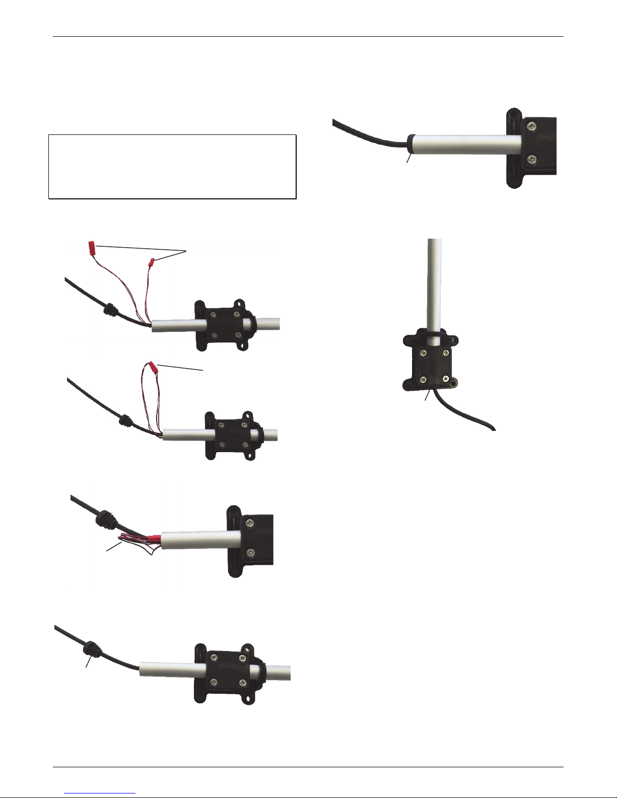
To connect the sensor battery:
1. Connect the two battery cables.
Battery cables unconnected
The cap should be fully seated in the sensor rod without
any gaps as shown below. If there is a gap, remove the cap
and push the battery cables further in the sensor rod to
make more room for the cap.
Cap fully seated
in sensor rod
4. Slide the sensor rod up so that the bottom is flush with the
bottom of the sensor base. Loosely tighten the four screws
to keep the sensor rod in place.
Battery cables
connected
2. Insert the connected battery cables into the sensor rod
tube.
Battery cables
being inserted
into sensor rod
3. Once the cables are fully inserted, push and twist the cap
into place at the end of the sensor rod.
Push this cap into
sensor rod end
Sensor rod flush
with bottom of
sensor base
Once these steps are complete, mount the sensor using the
guidelines in the next section.
Mounting
Mounting Guidelines
Use the following guidelines to determine the best location for
installing the sensor.
• The sensor can be damaged with improper handling. Store
the sensor in its shipping box until you are ready to install it.
• Mount the sensor in the sunlight within 10 days of
connecting the battery to prevent it from losing all charge.
• Choose a location free of turbulence and magnetic fields
resulting from electricity, engines, radio transmitters,
radars, etc.
• For the most accurate readings, the sensor should be
mounted 3 m (9.8 ft) or more above the ground and 10 m
(32.8 ft) away from nearby objects.
• When mounting the sensor on a roof, the sensor must be
mounted at a height equal to the building’s length or five
times the building’s height. Install the sensor in the middle
of the roof when possible. You may do this by mounting
the sensor on an Onset tripod or mast, or a metal pipe. It is
not recommended to install the sensor on a slanted roof
1-800-LOGGERS 2 www.onsetcomp.com
Ultrasonic Wind Speed and Direction Smart Sensor (S-WCG-M003) Manual
because it can generate upwards turbulence that will
affect the sensor measurements.
• You may mount the sensor on a wooden post.
• Mount the sensor in a location that receives direct sunlight
for several hours a day to ensure the built-in solar panel is
charged regularly. Make sure the sensor is positioned in
the sun and not under the forest canopy or obstructions.
• The sensor must be aligned to true north when mounted
to ensure accurate wind direction readings. Use the
alignment tool as described North Alignment.
• If the sensor is mounted on the same mast as a rain gauge,
mount the wind sensor away from the rain gauge on a half
cross arm (M-CAB) so that the wind sensor does not
interfere with rainfall measurements. If there is no rain
gauge on the same mast, mount the wind sensor directly
to the top of the mast.
• The tripod or mounting mast must be properly grounded.
For field installations, you can use Onset’s Grounding Kit
(M-GKA).
• If the station is deployed in an area subject to frequent
thunderstorms, installing a lightning rod nearby can
reduce the risk of damage.
• To minimize measurement errors due to ambient RF, keep
the sensor cable as far as possible from other cables
carrying high frequency or high-current signals.
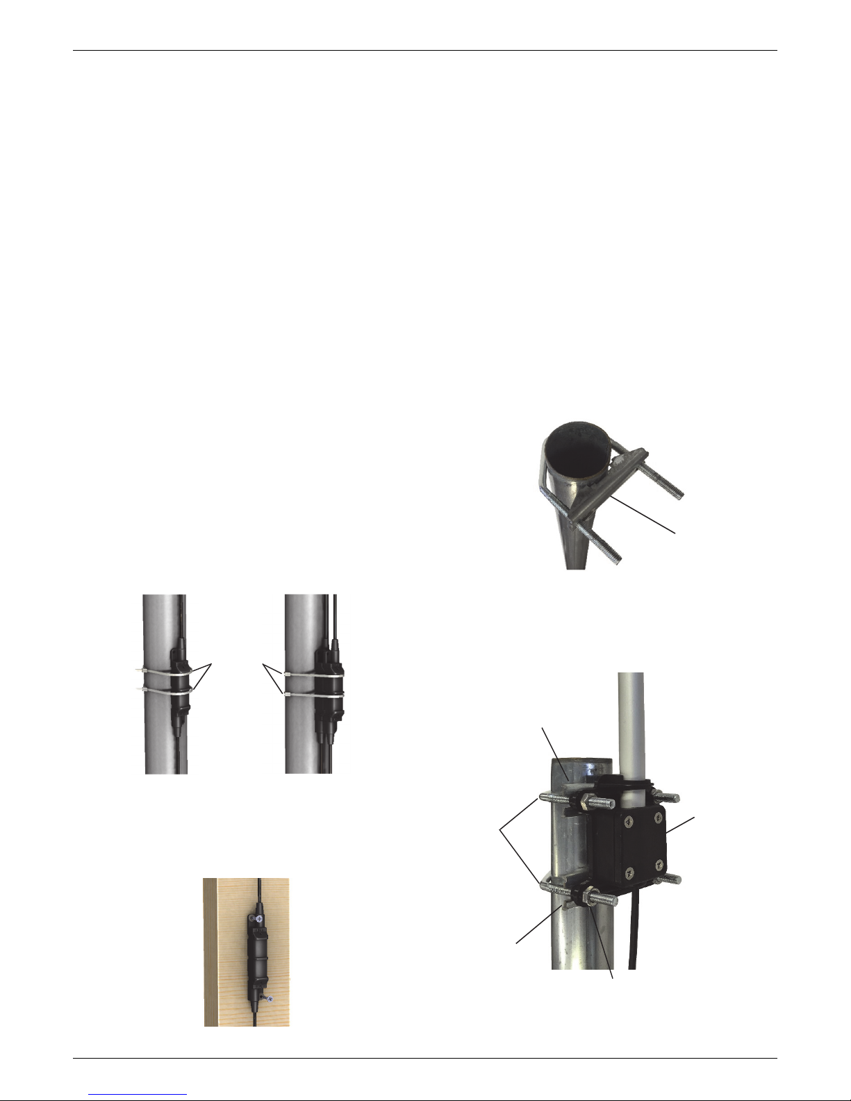
• After the sensor is mounted on a mast, secure the smart
sensor adapter to the mast with the cable ties as shown.
Multiple smart sensor adapters can be stacked as shown
in the example below on the right.
Smart sensor
adapter secured
with cable ties
• Secure the sensor cable with cable clips or weather
resistant cable ties to protect it from damage in the wind.
Place clips or cable ties approximately every 1 to 1.6 m (3
to 5 ft). Do not use metal staples to secure the cable as
they can cut the cable.
• Secure the mast that the sensor is mounted on so that it
does not vibrate. If you are using an Onset mast or tripod,
secure it with guy wires.
Mounting on a Mast
Follow these instructions for mounting the sensor on a tripod
or mast. The mounting U-bolts included can be used for
mounting the sensor on a mast or tripod with an outside
diameter ranging from 35–48 mm (1.38–1.89 inches).
1. Connect the battery if you haven’t already done so (see
Connecting the Sensor Battery).
2. Place the mounting U-bolt around the mast and slide the
bracket over the threaded U-bolt ends as shown in this
example. Make sure the flat part of the bracket is facing
out.
Mounting
bracket, flat
side facing out
3. Repeat step 2 with the other U-bolt and bracket.
4. Insert the ends of the U-bolts through the four holes in the
square sensor base at the bottom of the sensor rod. Loosely
install the hex nuts on the four bolt ends with a 10 mm
wrench.
One Smart Sensor
Adapter Mounted
Two Smart Sensor
Adapters Stacked
and Mounted
Alternatively, mount the smart sensor adapter to a flat
surface using two screws (no larger than a #6) and two
washers as shown in the example below.
1-800-LOGGERS 3 www.onsetcomp.com
Mounting
bracket
Mounting
U-bolts
around
mast
Mounting
bracket
One of four hex nuts
installed
Mounting base at
the bottom of the
sensor
 Loading...