

Page 1
Temperature/RH Smart Sensor (S-THB-M00x) Manual
W
The temperature/RH smart sensor is designed to work with smart sensor-compatible HOBO®
data loggers and stations. All sensor parameters are stored inside the smart sensor, which
automatically communicates configuration information to the logger without any
programming, calibration or extensive user setup.
Specifications
Temperature RH
Measurement Range -40°C to 75°C (-40°F to 167°F) 0-100% RH at -40° to 75°C (-40° to
Temperature/RH
Smart Sensor
Models: S-THB-M002
S-THB-M008
Accessories:
• Solar radiation shield
(M-RSA or RS3-B)
• Replacement RH sensor
(HUM-RHPCB-2)
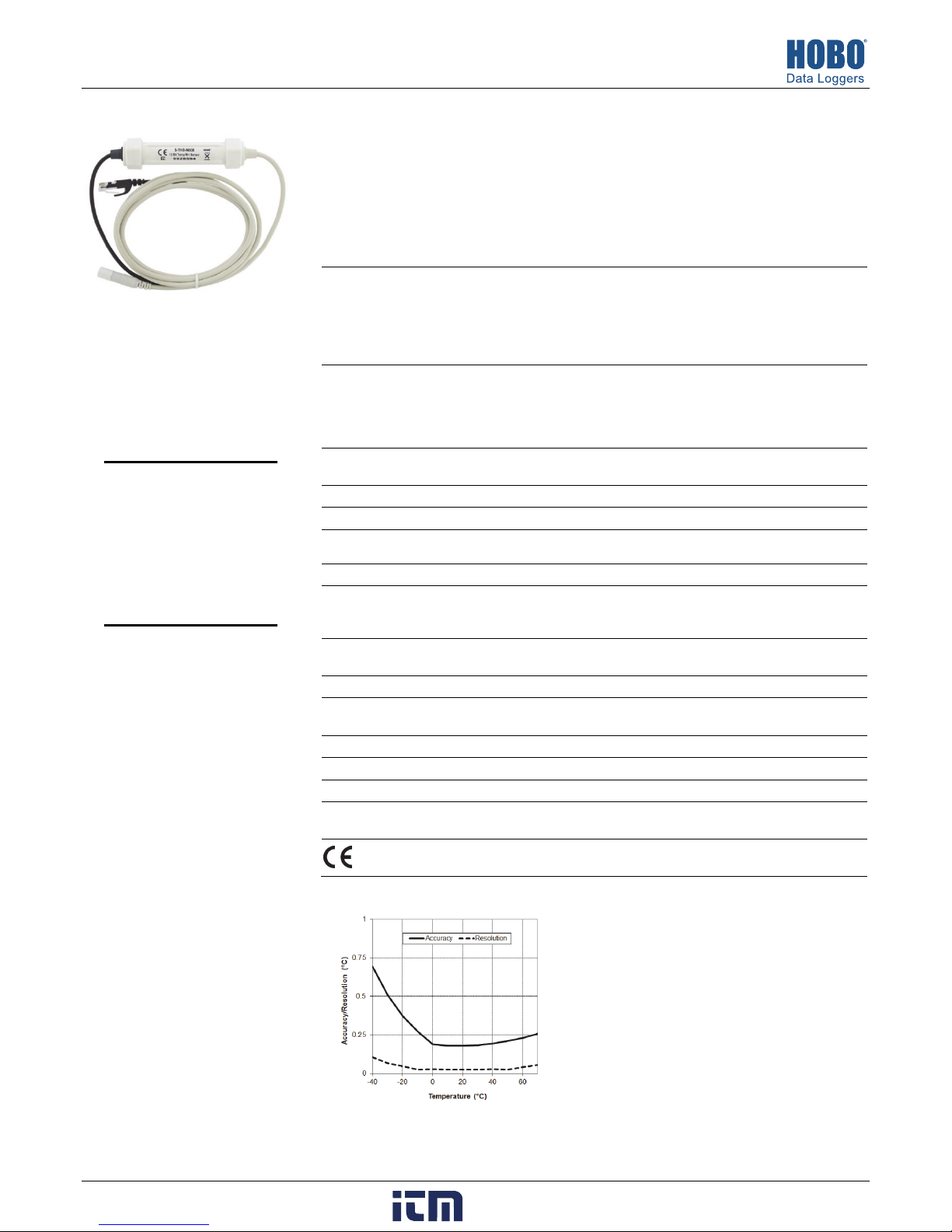
Accuracy ±0.21°C from 0° to 50°C (±0.38°F
Resolution 0.02°C at 25°C (0.04°F at 77°F);
Bits Per Sample 12 10
Drift
Response Time
Operating Temperature Range -40°C to 75°C (-40°F to 167°F)
Environmental Rating Weatherproof: 0 to 100% RH intermittent condensing environments.
Housing PVC cable jacket with ASA styrene polymer RH sensor cap; modified
Sensor Dimensions 10 x 35 mm (0.39 x 1.39 in)
eight
Number of Data Channels* 2
Measurement Averaging Option No
Cable Lengths Available
Length of Smart Sensor
Network Cable*
* A single HOBO station can accommodate 15 data channels and up to 100 m (328 ft) of smart sensor cable (the digital
communications portion of the sensor cables).
from 32° to 122°F); see Plot A
see Plot A
<0.1°C (0.18°F) per year <1% per year typical
5 minutes in air moving 1 m/sec 5 minutes in air moving 1 m/sec
For best results, the temp/RH smart sensor should be mounted inside
a protective enclosure, such as a solar radiation shield.
hydrophobic polyethersulfone membrane
S-THB-M002: 110 g (3.88 oz);
S-THB-M008: 180 g (6.35 oz)
2.5 m (8.2 ft); 8 m (26.2 ft)
0.5 m (1.6 ft); 6 m (19.6 ft)
The CE Marking identifies this product as complying with all relevant
directives in the European Union (EU).
167°F); exposure to conditions
below -20°C (-4°F) or above 95%
RH may temporarily increase the
maximum RH sensor error by an
additional 1%
±2.5% from 10% to 90% RH
typical to a maximum of ±3.5%
including hysteresis at 25°C
(77°F); below 10% and above
90% ±5% typical
0.1% RH
with protective cap
11427-M MAN-S-THB
Plot A: Temperature Accuracy and
Resolution
www. .com
information@itm.com1.800.561.8187
Page 2
Temperature/RH Smart Sensor (S-THB-M00x) Manual
Mounting
Typical Mounting
Solar Radiation Shield: Use
the washer and screw
(included with the M-RSA
radiation shield) or cable
clamps (included with the
RS3-B radiation shield) to
secure the smart sensor in
the radiation shield as shown
at right and below.
Temp/RH Sensor mounted in the
Solar Radiation Shield M-RSA
Temp/RH Sensor mounted in
Solar Radiation Shield RS3-B (cross-section)
Mounting Considerations
• A solar radiation shield is strongly recommended when
measuring air temperature in direct sunlight. Solar radiation
can be a significant source of error in the temperature and
RH readings.
• When mounting the probe, care should be taken to thermally
isolate the sensor from the mounting surface to ensure
accurate air temperature and humidity readings. The probe’s
temperature sensor is at the end of the cable, just below the
cup.
• It is recommended that the probe be protected from direct
exposure to the weather. This will prolong the sensor
accuracy.
• If you are running sensor cables along the ground, it is
recommended that you use conduit to protect against
animals, lawn mowers, exposure to chemicals, and so on.
• To provide long-term protection from moisture entry, the
smart sensor adapter must be mounted horizontally and with
the cable wires routed with drip loops so that water drains
away from the cable entry point as shown in the next
column. When mounted properly, the housing is
weatherproof (but not waterproof).
• Refer to the station manual and Tripod Setup Guide for more
information regarding setting up stations.
Smart
sensor
adapter
mounted
horizontally
Drip
loop
Drip loop
Connecting the Sensor to a Station or Logger
To connect the sensor to a station or logger, stop the station or
logger from logging and insert the smart sensor’s modular jack
into an available smart sensor port. See the station manual for
details on operating stations or loggers with smart sensors.
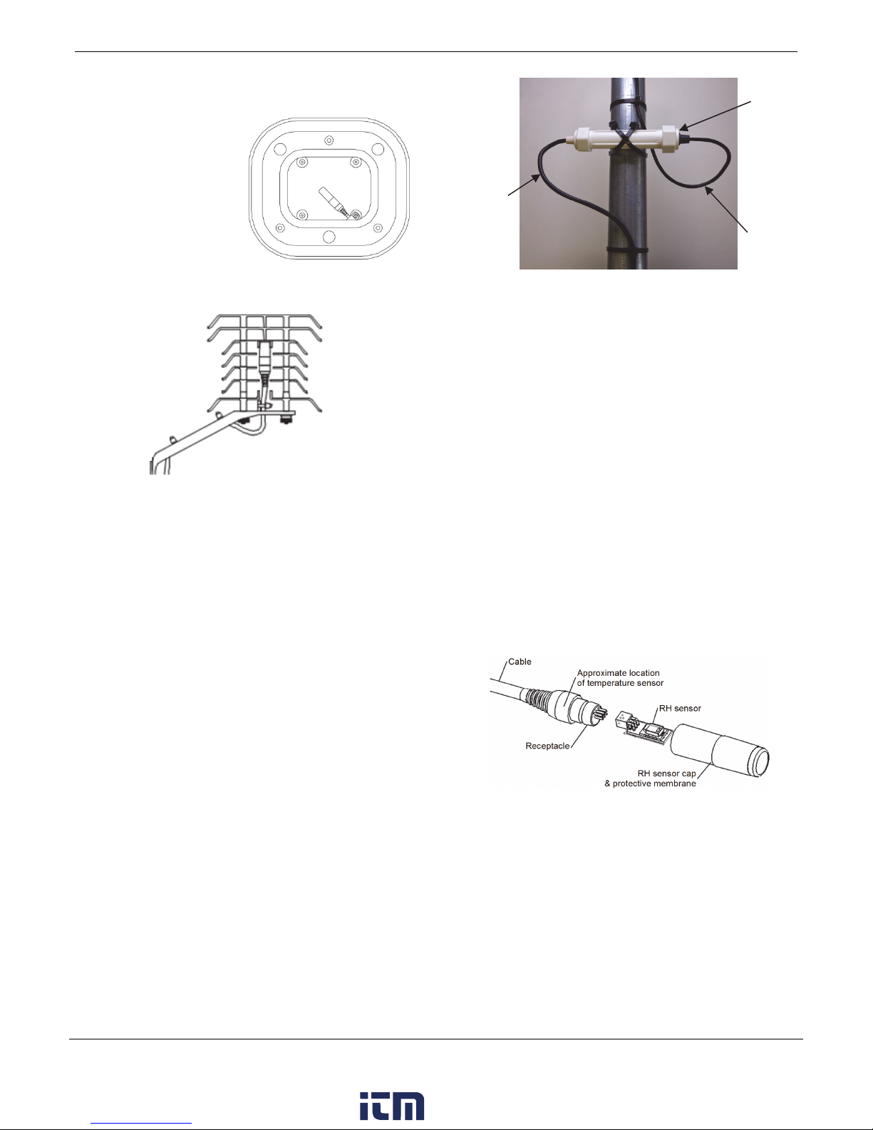
Replacing the RH Sensor
The RH sensor is protected by an ASA styrene polymer cap and
a modified hydrophobic polyethersulfone fluid barrier
membrane that allows vapor to penetrate while protecting the
sensor from condensation. RH sensor performance may
degrade over time. To replace the RH sensor, take the following
steps:
1. Remove the tape fastening the sensor cap to the receptacle.
Discard the tape.
2. Grasp the cap and membrane and pull firmly to remove
them. Discard them.
3. Note the orientation of the small circuit board containing
the RH sensor. Pull it out and discard it in compliance with
local disposal guidelines for circuit boards.
4. Push gently but firmly to install the new sensor (HUMRHPCB-2) in the same orientation.
5. Put the new sensor cap and membrane on. Do not force the
cap. If it does not go on easily, the sensor may be installed
backwards. Reverse the sensor and try again.
Maintenance
The temperature/RH smart sensor is sensitive to dust, salts and
other airborne contamination. Periodically inspect the RH
sensor. If contamination is present on the protective cap, gently
rinse it with cool fresh water. If the sensor itself is
contaminated, you can rinse it with distilled water. Do not use
hot water, organic solvents, or detergents. Dry before use.
© 2008–2017 Onset Computer Corporation. All rights reserved. Onset and HOBO are trademarks or registered
trademarks of Onset Computer Corporation. All other trademarks are the property of their respective
companies.
www. .com
11427-M MAN-S-THB
information@itm.com1.800.561.8187
 Loading...