

Page 1
15 Watt Solar Panel Installation Instructions (SOLAR-15W)
Items Included
• 15 watt solar panel with adjustable bracket mounting
hardware (tilt arm, bracket, clamps, bolts, lock washers,
washers, and nuts; additional optional hardware may be
included that is not required for this installation)
• Two U-bolts with saddle and two flanged nuts for
mounting solar panel to a 4.1 cm (1.63 in.) diameter mast
Tools Required
Note: Both Metric and English sizes are required.
• One 10 mm wrench
• Two ½ inch wrenches
Important: The solar panel must be mounted where it will
receive full sunlight or performance will be severely degraded.
Remove any plastic on the solar panel or hardware. It is
1
recommended that you lubricate all nuts and bolts with
multi-purpose or protective lithium grease to facilitate
easy removal at a later date. Two people may be needed
to perform some of these installation steps.
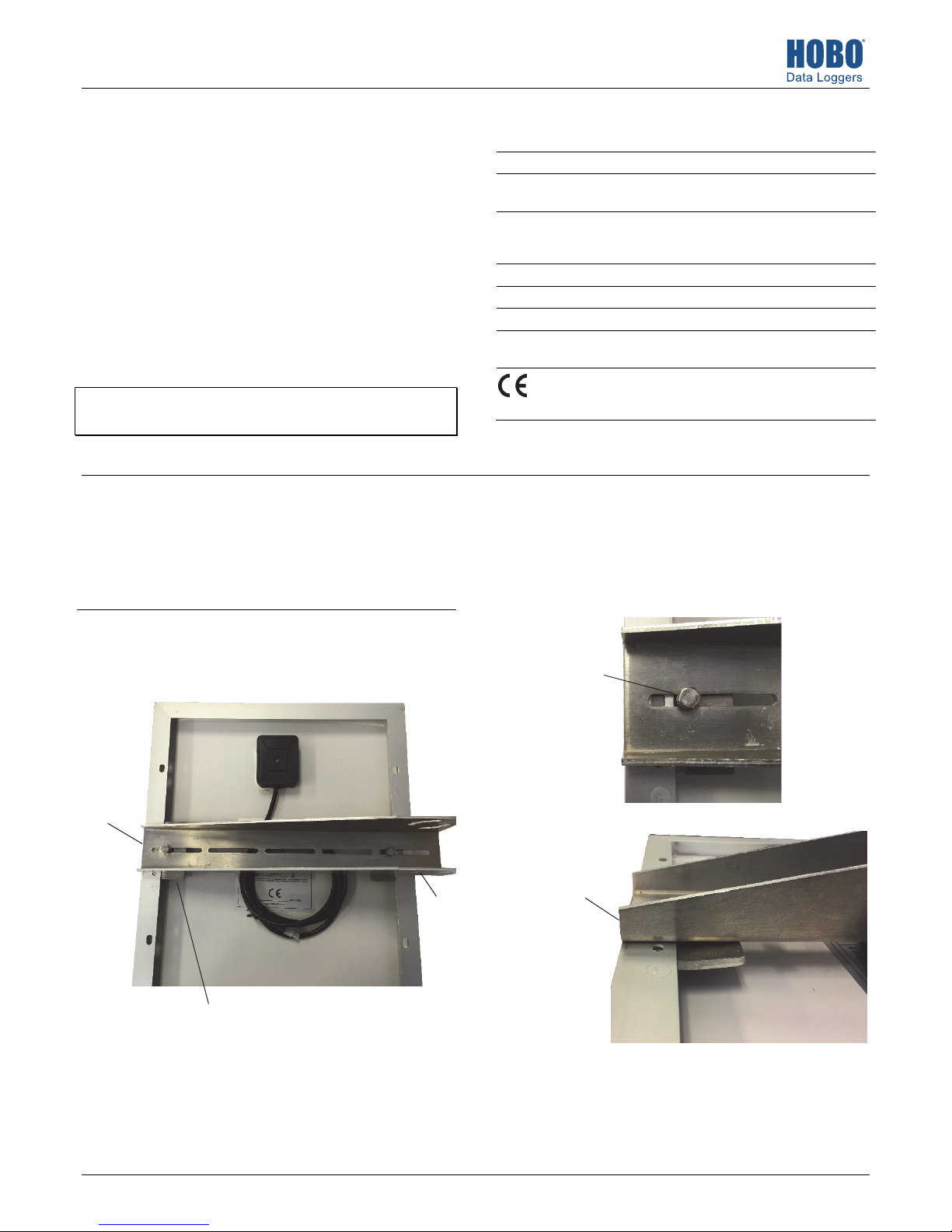
a. With the cable side of the solar panel facing up, center
2
the tilt arm on the solar panel, oriented as shown with
the shorter end of the tilt arm flush against the edge of
the solar panel frame.
Tilt arm flush
with edge of
solar panel,
(bolt assembly
will be added
in next steps)
Specifications
Power 15 Watts
Operating
Temperature Range
Materials Polycrystalline silicon solar cell; aluminum
Dimensions 428 x 357 x 30 mm (16.85 x 14.06 x 1.18 in)
Weight 2.2 kg (4.85 lb)
Cable Length 2 m (6 ft)
Environmental Rating Weatherproof when mounted properly, not
c. Place a lock washer, small washer, and medium washer
on the 20 mm (0.79 in.) bolt with the 10 mm head (the
lock washer is closest to the bolt head). Insert the
bolt/washer assembly through the slot in the tilt arm
and into the hole in the clamp as shown. Use a 10 mm
wrench to loosely tighten the bolt.
Bolt/washer
assembly
inserted
through slot in
tilt arm and
into clamp
below
-40° to 85°C (-40°F to 185°F)
frame and mounts; zinc-coated steel bolts,
nuts, washers, and U-bolts
waterproof
The CE Marking identifies this product as
complying with all relevant directives in the
European Union (EU).
Slide clamp below tilt arm
(described in step 2b)
b. Working on the flush edge first, slide a clamp under the
edge of the frame, lining up the hole in the center of
the clamp with the slot in the tilt arm.
21932-C MAN-SOLAR-15W
Side view of
proper tilt
arm/clamp
assembly
Large end of tilt
arm centered
on back of panel
(bolt assembly
will be added in
next steps)
d. Repeat steps 2b through 2c with the opposite side of
the tilt arm.
e. Tighten both bolts with the 10 mm wrench. Do not
overtighten the bolts.
Page 2
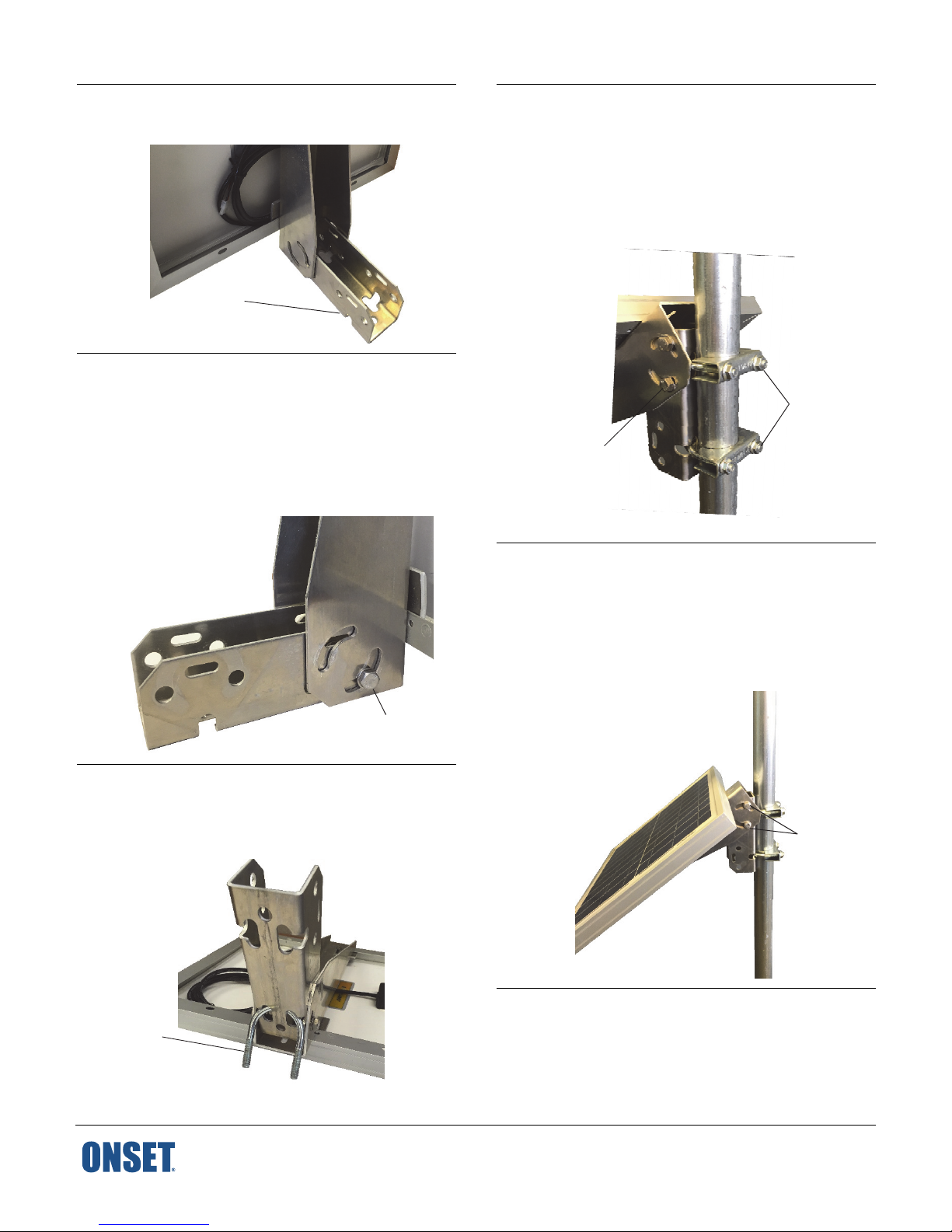
Insert the bracket into the larger end of tilt arm as shown.
3
The solar panel may not stand on its own; be sure to
support it.
Bracket
inserted into
tilt arm
Insert the larger bolt and medium washer into the bottom
4
arc hole on the tilt arm, making sure it protrudes through
the hole in the bracket. Place a medium washer and large
lock washer on the end of the bolt inside of the bracket
and finger tighten. Repeat with one other bolt in the
bottom arc hole on the opposite side of the tilt arm. Do
not install the two other bolts in the remaining arc holes
yet because you will need the bracket to be moveable
when inserting the U-bolt in the next step.
Insert the remaining two larger bolts and medium
6
washers into the other arc hole on the tilt arm as done in
step 4. Place a medium washer and large lock washer on
the end of the bolts inside of the bracket and finger
tighten. Insert the other U-bolt through the bracket and
attach it to the mast as shown. Attach the U-bolt saddles
and move the bracket to the desired position on the mast.
Use a ½ inch wrench to tighten the flanged nuts on the Ubolt assemblies.
U-bolt
assemblies
attaching
Second bolt
assembly in other
arc hole connecting
tilt arm to bracket
bracket to
mast
To adjust the angle of the solar panel, loosen the bolts on
7
the tilt arm and reposition them in the arc holes. Adjust
the angle to maximize the amount of light directed at the
solar panel during periods of the shortest duration of
daylight. Once the solar panel is at the desired angle, use
two ½ inch wrenches to tighten the bolts (one to hold the
bolt head steady, the other to tighten the lock washer
inside the bracket).
Bolt assembly in bottom arc
hole connecting tilt arm to
bracket
Insert a U-bolt through the bottom two holes in the
5
bracket as shown below. Adjust the bracket as necessary
to fit the U-bolt through the holes. Return the bracket to
its perpendicular position against the tilt arm once the
U-bolt is in place.
Insert a U-bolt
in the two
holes closest
to the solar
panel
1-800-LOGGERS (564-4377) • 508-759-9500
www.onsetcomp.com/support/contact
Reposition the
bolts on the
tilt arm to
adjust the
angle of the
solar panel
Make sure the battery is connected in the HOBO station
8
and then plug the solar panel cable into the station’s
charging port. Refer to the HOBO station user’s manual at
www.onsetcomp.com/support/manuals for the location
of the charging port on the station. Use zip ties to secure
the cable against the mast.
© 2017–2018 Onset Computer Corporation. All rights reserved. Onset and HOBO are registered trademarks
of Onset Computer Corporation. All other trademarks are the property of their respective companies.
21932-C MAN-SOLAR-15W
 Loading...