

HOBOnet® Wireless Sensor Network
W
O
C
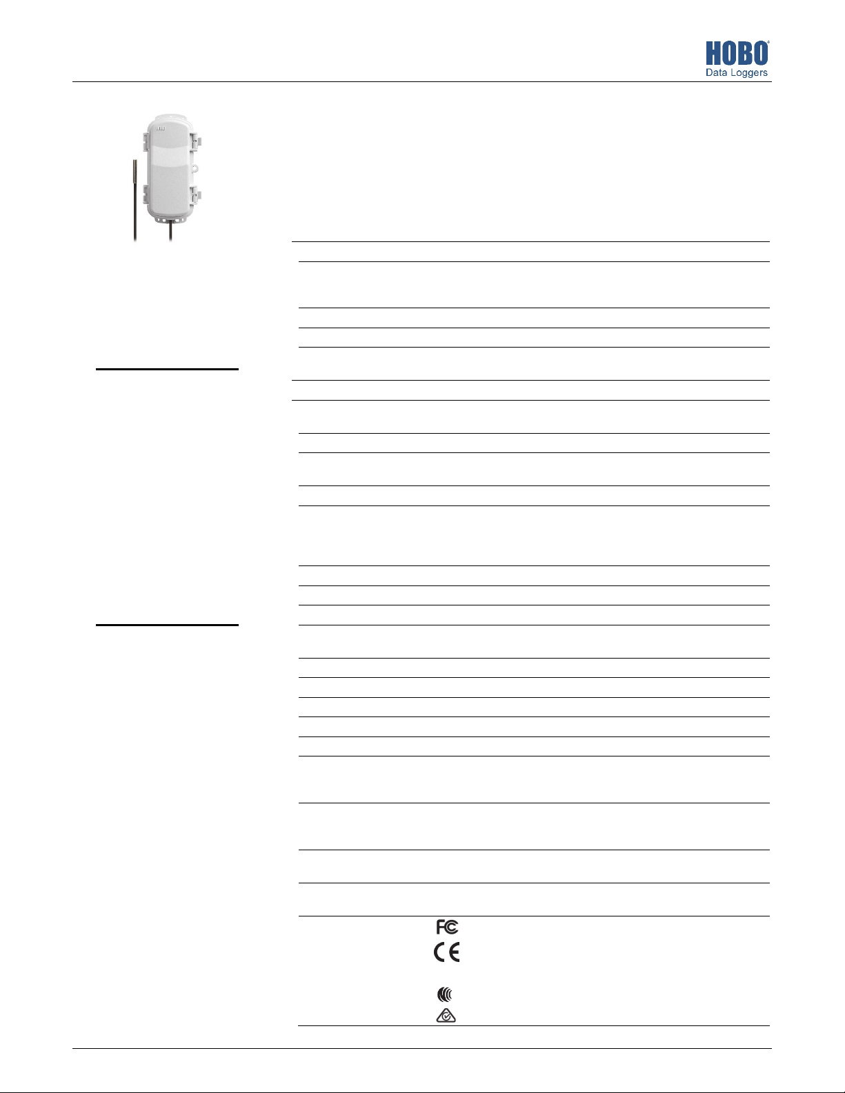
RXW Temperature Sensor (RXW-TMB-1-xxx and RXW-TMB-6-xxx) Manual
This sensor measures temperature and is designed to work with the HOBOnet (HOBO® RX)
Wireless Sensor Network in which data is transmitted wirelessly from the sensor mote across
the network to the station and then uploaded to HOBOlink® web-based software. With
HOBOlink, you can monitor sensor readings, view graphs, set up alarms, download data, and
more.
Specifications
Sensor
Measurement Range -40° to 100°C (-40° to 212°F)
RXW Temperature
Sensor
Models:
• RXW-TMB-1-900 and
RXW-TMB-6-900 (US)
• RXW-TMB-1-868 and
RXW-TMB-6-868
(Europe)
• RXW-TMB-1-921 and
RXW-TMB-6-921
(Taiwan)
• RXW-TMB-1-922 and
RXW-TMB-6-922
(Australia/NZ)
Included Items:
• Cable ties
• Screws
Accuracy ±0.25°C from -40° to 0°C (±0.45°F from -40° to 32°F)
Resolution 0.02°C (0.036°F)
Drift <0.01°C (0.018°F) per year
Response Time (typical, to
90% of change)
ireless Mote
perating Temperature
Range
Radio Power 12.6 mW (+11 dBm) non-adjustable
Transmission Range Reliable connection to 457.2 m (1,500 ft) line of sight at 1.8 m (6 ft) high
Wireless Data Standard IEEE 802.15.4
Radio Operating
Frequencies
Modulation Employed OQPSK (Offset Quadrature Phase Shift Keying)
Data Rate Up to 250 kbps, non-adjustable
Duty Cycle <1%
Maximum Number of
Motes
Logging Rate 1 minute to 18 hours
Number of Data Channels 2
Battery Type Two AA 1.5 V lithium batteries
Battery Life 1 year, typical use
Memory 16 MB
Dimensions Sensor: 5.3 x 33 mm (0.2 x 1.3 inches)
Weight Sensor and cable: 7.6 g (0.27 oz), RXW-TMB-1-xxx; 35.2 g (1.24 oz), RXW-
Materials Sensor: Stainless steel waterproof tip
Environmental Rating Sensor and cable: Immersion in water up to 50°C (122°F) for 1 year
ompliance Marks
±0.20°C from 0° to 70°C (±0.36°F from 32° to 158°F)
±0.25°C from 70° to 100°C (±0.45°F from 158° to 212°F)
2 minutes, 30 seconds in air moving 1 m/sec
-40° to 70°C (-40° to 158°F)
Reliable connection to 609.6 m (2,000 ft) line of sight at 3 m (10 ft) high
RXW-TMB-x-900: 904–924 MHz
RXW-TMB-x-868: 866.5 MHz
RXW-TMB-x-921: 921 MHz
RXW-TMB-x-922: 916–924 MHz
Up to 50 wireless sensors or 336 data channels per one HOBO RX station
Cable length: 0.3 m (1 ft), RXW-TMB-1-xxx; 1.8 m (6 ft), RXW-TMB-6-xxx
Mote: 16.2 x 8.59 x 4.14 cm (6.38 x 3.38 x 1.63 inches)
TMB-6-xxx
Mote: 223 g (7.87 oz)
Mote: PCPBT, silicone rubber seal
Mote: IP67, NEMA 6
RXW-TMB-1-900 and RXW-TMB-6-900: See last page.
RXW-TMB-1-868 and RXW-TMB-6-868: The CE Marking
identifies this product as complying with all relevant directives
in the European Union (EU).
RXW-TMB-1-921 and RXW-TMB-6-921: See last page.
RXW-TMB-1-922 and RXW-TMB-6-922: See last page.
25547-B
RXW Temperature Sensor (RXW-TMB-1-xxx and RXW-TMB-6-xxx) Manual
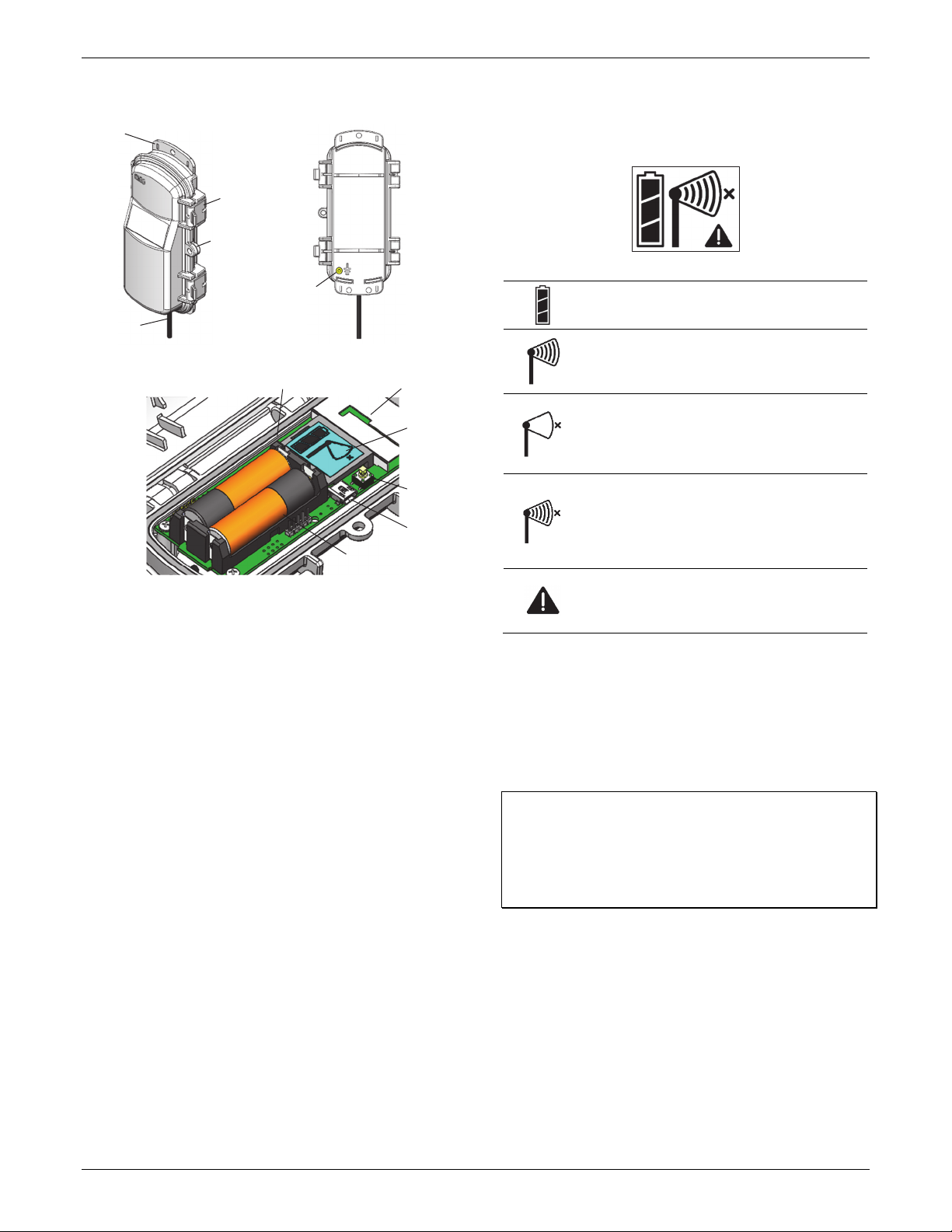
Mote Components and Operation
Mounting
Tab
Latch
Eyelet
Ground Wire
Port
Sensor Cable
Sensor Mote Closed, Front Sensor Mote Closed, Back
Mounting Tab: Use the tabs at the top and bottom of the mote
to mount it (see Deploying and Mounting).
Sensor Cable: This is the cable that connects the mote to the
sensor.
Eyelet: Use this eyelet to attach a 3/16 inch padlock to the
mote for security.
Latch: Use the two latches to open and close the mote door.
Ground Wire Port: Use this port to connect a ground wire (see
Deploying and Mounting).
Antenna: This is the built-in antenna for the radio
communications across the HOBOnet Wireless Sensor Network.
LEDs: There are two LEDs to the left of the LCD screen. The
green LED blinks during the process of joining a network,
blinking quickly while the mote searches for a network and
then slowly as the mote registers with the network. Once the
network registration process is complete, the blue LED blinks at
4 seconds to indicate normal operation. If the mote is not
currently part of a network, the blue LED will be off. If the blue
LED is on and not blinking, there is a problem with the mote.
Contact Onset Technical Support.
Battery Holder: The location where the batteries are installed
as shown (see Battery Information).
USB Port: Use this port to connect to the mote to a computer
via USB cable if you need to update the firmware (see Updating
Mote Firmware).
Button: Push this button for 1 second to illuminate the LCD or 3
seconds for the mote to search for an RX Wireless Sensor
Network to join (see Adding the Mote to the HOBOnet Wireless
Sensor Network).
LEDs
Battery Holder
Antenna
LCD Screen
Button
USB Port
Sensor Mote Opened
LCD Screen: The mote is equipped with an LCD screen that
displays details about the current status. This example shows all
symbols illuminated on the LCD screen followed by definitions
of each symbol in the table.
LCD Symbol Description
The battery indicator shows the approximate battery
charge remaining.
This is a signal strength indicator. The more bars, the
stronger the signal between motes. If there is no x
icon next to the signal strength indicator, then the
mote is part of a HOBOnet Wireless Sensor Network.
An empty signal strength icon plus the x icon
indicates that the mote is not currently part of a
network. See Adding the Mote to the HOBOnet
Wireless Sensor Network for details on how to add a
mote to the network.
When the mote is in the process of joining a
network, the signal strength icon will blink and then
the bars in the icon will cycle from left to right. The x
icon will blink during the last step in the network
registration process (see Adding the Mote to the
HOBOnet Wireless Sensor Network for details).
This indicates a problem with the sensor itself (the
mote is operational). Check the sensor and make any
adjustments to it as needed. Contact Onset
Technical Support if the problem persists.
Adding the Mote to the HOBOnet Wireless
Sensor Network
The mote must join a HOBOnet Wireless Sensor Network
before it can begin measuring temperature and transmitting
data. This requires accessing the station and the mote at the
same time so it is recommended that you complete these steps
before deploying the mote.
Important: If you are setting up a new station, follow the
instructions in the station quick start before setting up this
mote (go to www.onsetcomp.com/support/manuals/24380man-rx2105-rx2106-qsg for RX2105 and RX2106 stations or go
to www.onsetcomp.com/support/manuals/18254-MAN-QSGRX3000 for RX3000 stations).
To add a mote to the network:
1. If the LCD is blank on the station, press any button to wake
it up.
1-508-759-9500 (U.S. and International) 2 www.onsetcomp.com
1-800-LOGGERS (U.S. only)

RXW Temperature Sensor (RXW-TMB-1-xxx and RXW-TMB-6-xxx) Manual
2. Press the Select button once (which shows the number of
smart sensors installed) and then press it again to switch to
the module with the manager.
Press this button to view the module
3. Press the Search button (the magnifying glass). The
magnifying glass icon will blink while the station is in search
mode.
Press this button so the station is ready
to have motes join the network
4. Open the mote door and install the batteries if you have not
already done so.
5. Press the button on the mote for 3 seconds. The signal
strength icon will flash and then cycle.
Press this button
for 3 seconds for
the mote to join
the network
6. Watch the LCD on the mote.
network, the green LED turns off and the blue LED then
blinks indefinitely while the mote is part of the network.
Note: If the mote cannot find the network or has trouble
remaining connected during this process, make sure the
mote is in a vertical, upright position and within range of
the station.
7. Press the Search button (the magnifying glass) on the
station to stop searching for motes.
Press this button again to stop
searching for motes
If you added more than one more mote to the network, then
the total channel count on the station LCD for the manager
module will represent all measurement channels plus a battery
channel for each mote in the network.
Sensor measurements will be recorded at the logging interval
specified in HOBOlink, transmitted to the station, and uploaded
to HOBOlink at the next connection interval (readout). Use
HOBOlink to monitor mote status and health. If a mote is
temporarily offline, any logged data is saved until it is back
online. In addition, if a mote is offline for 30 minutes, the
station will automatically connect to HOBOlink and report the
mote as missing. Once the mote is back online, any logged data
will be uploaded the next time the station connects to
HOBOlink.
See the HOBOlink Help for details on how to change the logging
and connection intervals, view data, check mote status, add the
mote to a map, and more.
a.
This signal strength icon
blinks while searching for
a network.
c.
b.
Once a network is found,
the icon will stop flashing
and the bars will cycle from
left to right.
d.
Deployment and Mounting
Mounting and Positioning the Mote
• Mount the mote to a mast or pipe using cable ties or affix
the mote to a wooden post or flat surface with screws.
Insert the cable ties or screws through the holes on the
mounting tabs.
• Consider using plastic poles such as PVC to mount the
mote as certain types of metal could decrease signal
strength.
This network connection
“x” icon blinks while the
mote completes the
registration process.
which may take up to
five minutes.
Once the mote has finished joining
the network, the “x” icon is
removed and the channel count
on the station LCD increases by
two (one for temperature and one
for the mote battery).
This process may take up to five minutes. The green LED
• Make sure the mote remains in a vertical position once it
is placed in its deployment location for optimal network
communications.
• Make sure the mote door is closed, with both latches fully
locked to ensure a watertight seal.
• Consider using a 3/16 inch padlock to restrict access to the
mote. With the mote door closed, hook a padlock through
the eyelet on the right side of the door and lock it.
blinks quickly while the mote searches for a network to join
and then blinks slowly while it completes the network
registration. Once the mote has finished joining the
1-508-759-9500 (U.S. and International) 3 www.onsetcomp.com
1-800-LOGGERS (U.S. only)

RXW Temperature Sensor (RXW-TMB-1-xxx and RXW-TMB-6-xxx) Manual
• Make sure the mote is mounted a minimum of 1.8 m (6 ft)
from the ground to help maximize distance and signal
strength.
• Place the mote so there is full line of sight with the next
mote. If there is an obstruction between two sensor
motes or between the sensor mote and the manager, then
use a repeater mounted on the obstruction.
• There should not be more than five motes in any direction
at their maximum transmission range from the manager.
Data logged by a wireless sensor must travel or “hop”
across the wireless network from one mote to the next
until it ultimately reaches the manager connected to the
station. To make sure the data can successfully travel
across the network, the mote should not be more than
five hops away from the manager.
• The HOBOnet Wireless Sensor Network can support up to
50 wireless sensors or 336 data channels per one HOBO
RX station.
• Use a #4-40 screw to attach a ground wire to the port on
the back of the mote if you are deploying the mote in a
location where lightning is a concern.
Sensor Mounting Guidelines
• Mount the sensor so that at least 10 cm (4 inches) of the
sensor cable is placed in the medium that is being
measured. The temperature sensor is approximately 0.32
cm (0.126 inches) from the end of the stainless steel tip.
• To minimize measurement errors due to ambient RF, keep
the probe cable as far as possible from other cables.
• Refer to the station manual and Tripod Setup Guide at
www.onsetcomp.com/support/manuals for more
information regarding setting up stations.
Sensor Operating Environment
The temperature sensor can be used in air, soil, or water. The
sensor is designed to last at least one year in water as warm as
50°C (122°F). If the sensor is continually exposed to water for
more than a year, it will eventually drift. Exposure to water
above 50°C (122°F) is not recommended and may significantly
reduce the life of the sensor.
Maintenance
The temperature sensor does not require any maintenance
other than an occasional cleaning. If necessary, rinse the sensor
and cable with mild soap and fresh water.
Periodically inspect the mote and do the following:
• Verify the mote is free of visible damage or cracks.
• Make sure the mote is clean. Wipe off any dust or grime
with a damp cloth.
• Wipe off any water before opening the mote.
• Make sure the interior seal is intact and the latches are
fully locked when the mote door is closed.
Verifying Sensor Accuracy
It is recommended that you check the accuracy of the
temperature sensor annually. The temperature sensor cannot
be calibrated. Onset uses precision components to obtain
accurate measurements. If the sensor is not providing accurate
data, then it may be damaged or worn out if it has been in use
for several years.
Updating Mote Firmware
If a new firmware version is available for the mote, use
HOBOlink to download the file to your computer.
1. In HOBOlink, go to Devices, then RX Devices, and click your
station name.
2. On the station page, click Overview and scroll down to
Device Information.
3. Click the Wireless tab. This icon appears next to the
mote if there is a new version of firmware available.
4. Click the firmware upgrade link. Click Download and
save the firmware .bin file to your computer.
5. Connect the mote to the computer with a USB cable (open
the mote door and use the USB port to the right of the
LCD). The blue LED is illuminated while connected.
6. The mote appears as a new storage device in the
computer’s file storage manager. Copy the downloaded
firmware file to the new storage device (the mote). The
blue LED will blink slowly while the file is copying.
7. After the file is copied to the mote, the LED will stop
blinking and remain a steady blue. Eject the storage device
from the computer and disconnect the cable from the
mote. The firmware installation process will begin
automatically on the mote. The blue LED will blink rapidly
while the firmware is installed. Once the firmware
installation is complete, the LCD symbols return and the
mote will automatically rejoin the network.
Notes:
• Mac® users: A message may appear indicating the disk
has not ejected properly when disconnecting the mote
from the computer. The mote is operational and you can
ignore the message.
• If the blue LED turns off abruptly while copying the file or
installing the firmware, a problem has occurred. Contact
Onset Technical Support for help.
Battery Information
The mote uses two 1.5 V lithium batteries (HWSB-LI). Lithium
battery life is an estimated at 1 year, but varies based on the
ambient temperature where the mote is deployed, the logging
interval, the number of tripped alarms, and other factors.
Estimates are not guaranteed due to uncertainties in initial
battery conditions and operating environment.
To install lithium batteries:
1. Open the mote door.
2. Remove any old batteries and install the new ones
observing polarity.
1-508-759-9500 (U.S. and International) 4 www.onsetcomp.com
1-800-LOGGERS (U.S. only)

RXW Temperature Sensor (RXW-TMB-1-xxx and RXW-TMB-6-xxx) Manual
The mote contacts the network once the new batteries are
installed. The green LED blinks quickly while the mote searches
for a network to join and then blinks slowly while it completes
the network registration. Once the mote has finished joining
the network, the green LED turns off and the blue LED then
blinks indefinitely while the mote is part of the network.
WARNING: Do not cut open, incinerate, heat above 85°C
(185°F), or recharge the lithium batteries. The batteries may
explode if the mote is exposed to extreme heat or conditions
that could damage or destroy the battery cases. Do not mix
battery types, either by chemistry or age; batteries may rupture
or explode. Do not dispose of the logger or batteries in fire. Do
not expose the contents of the batteries to water. Dispose of
the batteries according to local regulations for lithium
batteries.
Federal Communication Commission Interference Statement
This equipment has been tested and found to comply with the limits for a Class B digital device, pursuant to Part 15 of the FCC Rules. These limits are designed to provide
reasonable protection against harmful interference in a residential installation. This equipment generates uses and can radiate radio frequency energy and, if not installed and
used in accordance with the instructions, may cause harmful interference to radio communications. However, there is no guarantee that interference will not occur in a
particular installation. If this equipment does cause harmful interference to radio or television reception, which can be determined by turning the equipment off and on, the user
is encouraged to try to correct the interference by one of the following measures:
• Reorient or relocate the receiving antenna
• Increase the separation between the equipment and receiver
• Connect the equipment into an outlet on a circuit different from that to which the receiver is connected
• Consult the dealer or an experienced radio/TV technician for help
This device complies with Part 15 of the FCC Rules. Operation is subject to the following two conditions: (1) This device may not cause harmful interference, and (2) this device
must accept any interference received, including interference that may cause undesired operation.
FCC Caution: Any changes or modifications not expressly approved by the party responsible for compliance could void the user's authority to operate this equipment.
Industry Canada Statements
This device complies with Industry Canada license-exempt RSS standard(s). Operation is subject to the following two conditions: (1) this device may not cause interference, and
(2) this device must accept any interference, including interference that may cause undesired operation of the device.
Avis de conformité pour l’Industrie Canada
Le présent appareil est conforme aux CNR d'Industrie Canada applicables aux appareils radio exempts de licence. L'exploitation est autorisée aux deux conditions suivantes : (1)
l'appareil ne doit pas produire de brouillage, et (2) l'appareil doit accepter tout brouillage radioélectrique subi, même si le brouillage est susceptible d'en compromettre le
fonctionnement.
To comply with FCC and Industry Canada RF radiation exposure limits for general population, the logger must be installed to provide a separation distance of at least 20cm from
all persons and must not be co-located or operating in conjunction with any other antenna or transmitter.
NCC Statement
經型式認證合格之低功率射頻電機,非經許可,公司、商號或使用者均不得擅自變更頻率、加大功率或變更原設計之特性及功能。
低功率射頻電機之使用不得影響飛航安全及干擾合法通信;經發現有干擾現象時,應立即停用,並改善至無干擾時方得繼續使用。前項合法通信,指依電信法規定作
業之無線電通信。低功率射頻電機須忍受合法通信或工業、科學及醫療用電波輻射性電機設備之干擾。
Translation:
Article 12
Without permission granted by the NCC, any company, enterprise, or user is not allowed to change frequency, enhance transmitting power or alter original characteristic as well
as performance to an approved low power radio-frequency device.
Article 14
The low power radio-frequency devices shall not influence aircraft security and interfere with legal communications. If found, the user shall cease operating immediately until no
interference is achieved. The said legal communications means radio communications is operated in compliance with the Telecommunications Act. The low power radiofrequency devices must be susceptible with the interference from legal communications or ISM radio wave radiated devices.
1-508-759-9500 (U.S. and International)
1-800-LOGGERS (564-4377) (U.S. only)
www.onsetcomp.com/support/contact
© 2021 Onset Computer Corporation. All rights reserved. Onset, HOBO, HOBOnet, and HOBOlink are
registered trademarks of Onset Computer Corporation. Mac is a registered trademark of Apple Inc. All other
trademarks are the property of their respective companies.
25547-B
 Loading...