

Page 1
HOBO® RX3000 Remote Monitoring Station Manual
Operating
Smart
Smart Sensor Network Cable
Length
Smart Sensor Data
Module Slots
Logging Rate
Time Accuracy
Battery Type
Rechargeable
Service
Memory
Alarm Notification Latency
Enclosure Access
LCD
Materials
Size
Weight
Mounting
Environmental Rating
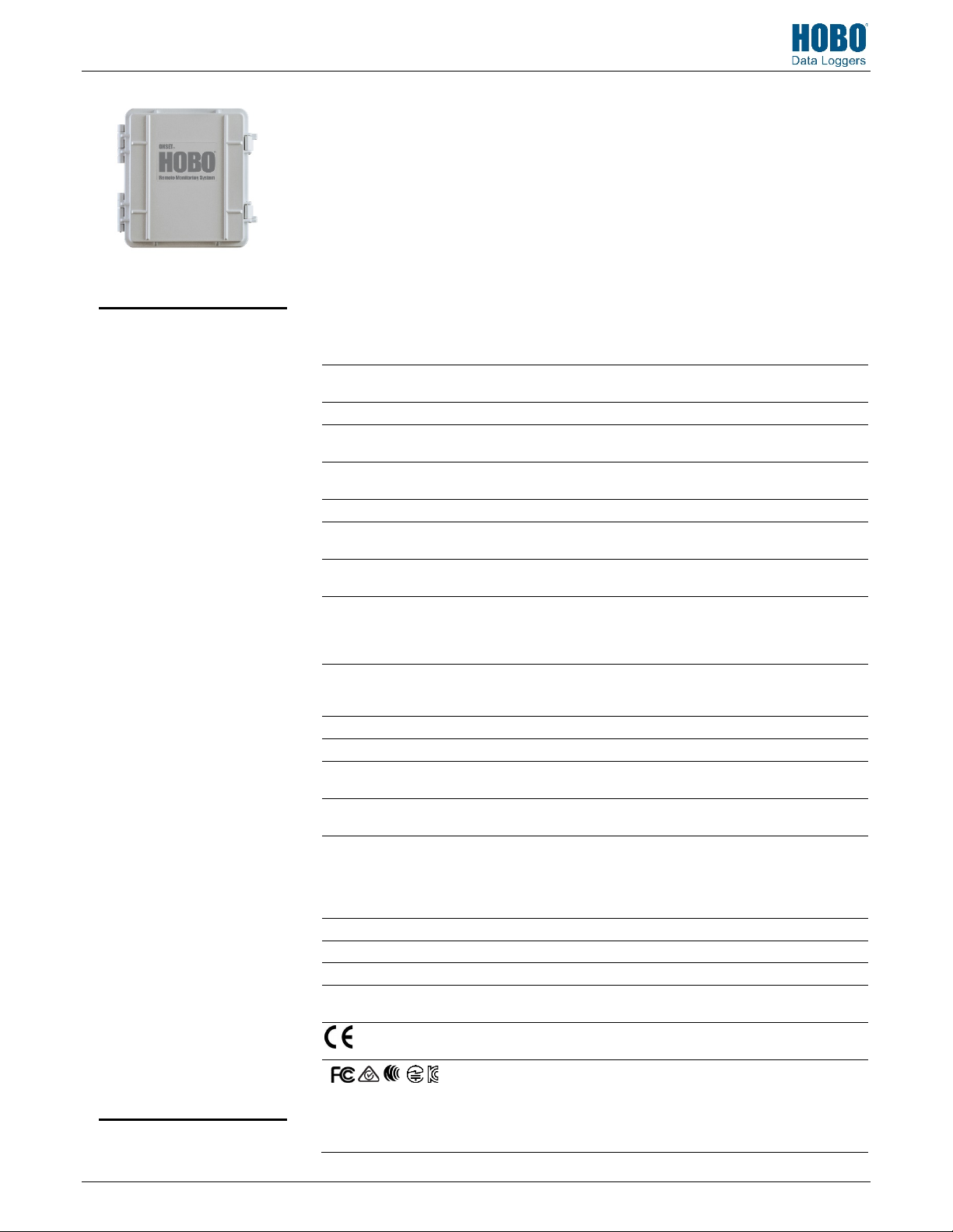
HOBO RX3000 Remote
Monitoring Station
Models: RX3001-00-01 Ethernet
Included Items:
• Two plates for cable access
openings with eight
thumbscrews and one wrench
• Two rubber cable channels
• Rubber plugs
• Grease packet
• Two mounting plates with
four screws
• Grounding wire
• Two U-bolts
Required Items:
• HOBOlink
• HOBOware
with USB cable for RX3002
Wi-Fi models (optional for
RX3001, RX3003, and RX3004
models)
• AC adapter (AC-U30) or solar
panel (SOLAR-xW)
Optional Items:
• Smart sensors
• Analog sensor module
(RXMOD-A1)
• Relay module (RXMOD-R1)
• RXW Manager (RXMOD-RXW-
xxx) and RXW motes
• Water level sensor module
(RXMOD-W1) with water level
sensor (MX2001-0x-SS-S or
MX2001-0x-Ti-S) and cable
(CABLE-RWLMOD-xxx)
• External DC power cable
(CABLE-RX-PWR)
• Tripod kit (M-TPA or M-TPB)
• Guy wire kit (M-GWA)
• 1/2 inch stake kit (M-SKA)
• Grounding kit (M-GKA),
required if using wind speed
or wind direction smart sensor
Sensors, modules, and
accessories are available at
www.onsetcomp.com.
18255-R
RX3002-00-01 Wi-Fi
RX3003-00-01 Cellular
RX3004-00-01 Cellular 4G
® 3.7.2 or later
The HOBO RX3000 Remote Monitoring Station provides continuous logging for a broad range of
energy and weather monitoring applications with up to ten smart sensors, optional analog sensor,
water level sensor, and relay modules, and wireless sensor motes. Data from the RX3000 station is
transferred at regular connection intervals to HOBOlink® web-based software where you can
check the latest conditions, view graphs, configure sensors and alarms, set up a dashboard,
download your data, or schedule data delivery via email or FTP. Inside its weatherproof enclosure,
this durable station has a built-in LCD screen to check the current system configuration and status,
start and stop logging, add and remove smart sensors, and connect to HOBOlink on demand. Up
to three individual relays can be activated on the optional relay module while the optional analog
module has four analog inputs that support excitation power, scaling, and statistics
measurements. An optional RXW Manager module is also available for the station to set up the
HOBOnet Wireless Sensor Network, which can support up to 50 motes. All easy-to-install modules
can be configured with HOBOlink.
Specifications
Range -40° to 60°C (-40° to 140°F); no remote communications for battery
Sensor Connectors 10
Channels Maximum of 15 (some smart sensors use more than one data channel;
2
1 second (RX3001 and RX3002) or 1 minute (RX3003 and RX3004) to 18
±8 seconds per month in 0° to 40°C (32°F to 104°F) range;
/Power Source 4 Volt, 10 AHr, rechargeable sealed lead-acid; external power required
Battery
Life
32 MB, 2 million measurements, continuous logging
Hinged door secured by two latches with eyelets for use with user-
LCD is visible from 0° to 50°C (32° to 122°F); the LCD may react slowly
Outer enclosure: Polycarbonate/PBT blend with stainless steel hinge
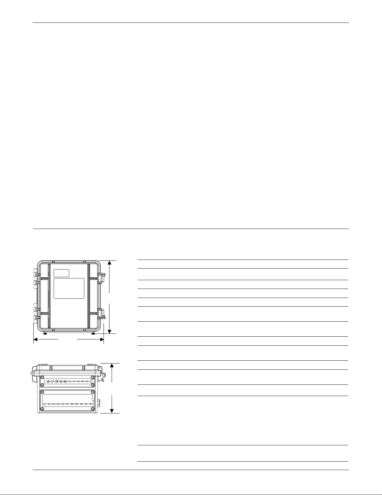
18.6 x 18.1 x 11.8 cm (7.3 x 7.1 x 4.7 in.); see diagrams on next page
2.2 kg (4.85 lb)
3.8 cm (1.5 inch) mast or wall mount
Weatherproof enclosure, NEMA 4X (requires proper installation of
voltage less than 3.9 V DC
100 m (328 ft) maximum
see sensor manual for details)
hours
±30 seconds per month in -40° to 60°C (-40° to 140°F) range
using one of these options: AC power adapter (AC-U30), solar panel
(SOLAR-xW), or external power source 5 V DC to 17 V DC with external
DC power cable (CABLE-RX-PWR)
Typical 3–5 years when operated in the temperature range -20° to 40°C
(-4°F to 104°F); operation outside this range will reduce the battery
service life
Logging interval plus 2–4 minutes, typical
supplied padlocks
or go blank in temperatures outside this range
pins and brass inserts; Inner enclosure: Polycarbonate; Gaskets:
Silicone rubber; Cable channel: EPDM rubber; Cable opening cover:
Aluminum with ABS plastic thumb screws; U-Bolts: Steel with zinc
dichromate finish
cable channel system)
The CE Marking identifies this product as complying with all relevant
directives in the European Union (EU)
See last page
RX3002: FCC ID R68XPICOW, IC ID 3867A-XPICOW
RX3003: FCC ID QIPEHS6, IC ID 7830A-EHS6; approved for use in
Taiwan and Japan
RX3004: FCC ID QIPPLS62-W, IC ID:7830A-PLS62W
Page 2
HOBO RX3000 Remote Monitoring Station Manual
Ethernet (RX3001)
Connector
Wi
Network Standards
Frequency Range
Antenna Connector
Data Rates
6, 9, 12, 18, 24, 36, 48, 54 Mbps (802.11g
Number of Selectable
Subchannels
Radio
Security
Maximum Receive Level
Receiver Sensitivity
Cellular (RX3003
Wireless Radio
Antenna
11.8 cm
4.7 in.
18.6 cm
(7.3 in.)
18.1 cm
Table of Contents
Specifications .......................................................................................... 1
Module Specifications ............................................................................. 3
Device Components and Operation ........................................................ 6
LCD Operation ......................................................................................... 7
Setting up the Station ............................................................................. 9
1. Log in to HOBOlink. ...................................................................... 9
2. Register the station. ..................................................................... 9
3. Install optional modules or user-supplied SIM. ............................ 9
4. Plug in the battery and charging device. ...................................... 9
5. Check and configure device communications. ........................... 10
6. Plug in and search for any smart sensors. .................................. 11
7. Add any wireless sensor motes. ................................................. 11
8. Connect analog sensors, relay devices, or water level sensors. . 12
9. Connect to HOBOlink. ................................................................ 13
10. Configure the station in HOBOlink. ............................................ 14
11. Start logging. .............................................................................. 17
12. If you installed a water level sensor module and sensor,
obtain a reference water level reading. ..................................... 17
13. If you installed a water level sensor module and sensor,
configure the water level and water flow channels in
HOBOlink. ................................................................................... 17
Viewing Data in HOBOlink ..................................................................... 18
Setting System and Sensor Alarms ........................................................ 19
System Alarms .................................................................................. 19
Sensor Alarms ................................................................................... 19
Setting up Water Level and Water Flow Channels in HOBOlink ............ 20
Setting up a Water Level Channel .................................................... 20
Setting up a Water Flow Channel for a V-Notch Weir ...................... 20
Setting up a Water Flow Channel for a Rectangular Weir ................ 21
Setting up a Water Flow Channel for a Trapezoidal Weir ................. 22
Setting up a Water Flow Channel for a General Flume .................... 23
Setting up a Water Flow Channel for a Stage-Discharge Table ......... 23
Starting and Stopping Logging .............................................................. 24
Adding or Removing Smart Sensors ...................................................... 25
Adding or Removing Modules ............................................................... 25
Adding or Removing Analog Sensors, Relay Devices, or Water Level
Sensors ................................................................................................. 26
Adding or Removing Motes .................................................................. 26
Managing Connections to HOBOlink ..................................................... 27
Checking Latest Conditions with HOBOware ........................................ 28
Deploying and Mounting the Station .................................................... 28
Guidelines for Deploying the Station................................................ 28
Guidelines for Deploying the HOBOnet RX Wireless Sensor
Network ..................................................................................... 28
Guidelines for Deploying a Water Level Sensor ............................... 29
Installing the Grounding Wire .......................................................... 30
Mounting the Station ....................................................................... 30
Installing the Weatherproof Rubber Cable Channel and Covers ..... 31
Care and Maintenance .......................................................................... 32
Troubleshooting.................................................................................... 32
Battery Information .............................................................................. 32
Specifications (continued)
(7.1 in.)
Dimensions
One RJ45/100BaseT
-Fi (RX3002)
IEEE 802.11b/g/n
2.412–2.484 GHz
1, no diversity supported
1, 2, 5.5, 11 Mbps (802.11b);
Radio
Modulations OFDM, DSSS, DBPSK, DQPSK, CCK, 16QAM, 64QAM
WEP 64/128, WPA-PSK, AES end-to-end encryption, WPA2,
-72 dBM for 54 Mbps, -87 dBm for 11 Mbps, -89 dBm for 5.5 Mbps,
and RX3004)
RX3003:
RX3003: Penta band
802.11n, HT20 MCS0 (6.5 Mbps) to HT20 MC87 (65 Mbps)
Up to 14 channels; profiles available will include USA, France, Japan,
Spain, Canada, and “Other” (multiple countries)
protocols not listed are not supported
-10 dBm (with PER <8%)
-90 dBm for 2.0 Mbps, -92 dBm for 1.0 Mbps
GSM/GPRS/EDGE: Quad band 850/900/1800/1900 MHz,
UMTS/HSPA+: Five band 800/850/900/1900/2100 MHz
RX3004:
GSM/GPRS/EDGE: Quad band 850/900/1800/1900 MHz
UMTS/HSPA+: Seven band 800/850/900/1800/1900/2100 MHz
LTE: Twelve Band 700/800/850/900/1800/1900/2100/2600 MHz
RX3004: 4G LTE
1-508-759-9500 (U.S. and International) 2 www.onsetcomp.com
1-800-LOGGERS (U.S. only)
Page 3
HOBO RX3000 Remote Monitoring Station Manual
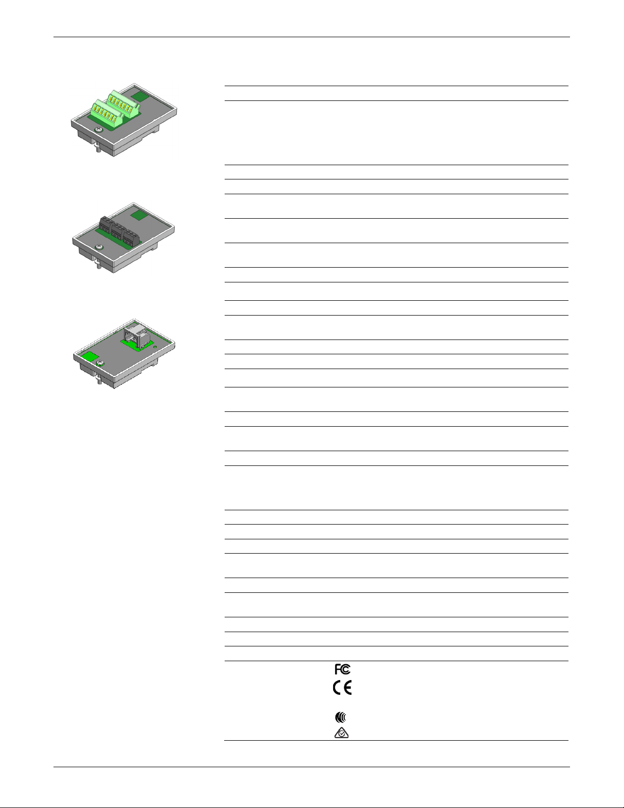
Optional Analog Sensor Module (RXMOD
Input Channels
Measurement Range
Accuracy
Resolution
Field Wiring
Minimum/Maximum Input
Voltage
Minimum/Maximum Input
Current
Minimum Source Impedance
for Current Measurement
Excitation Voltage
Optional Relay Module (RXMOD
Relays
Alarm Output Relays
Voltage
Current
Optional RXW Manager Module (RXMOD
Operating Temperature
Range
Radio Power
Transmission Range
At least 304.8 m (1,000 ft) line of sight at 1.8 m (6 ft) from the ground,
Wireless Data Standard
Radio Operating Frequencies
Modulation Employed
Data Rate
Duty Cycle
Maximum Number of Motes
Power Source
Dimensions
Weight
Materials
Environmental Rating
Compliance Marks
Module Specifications
-A1)
Four, single-ended, in addition to smart sensor data channels
Analog Sensor Module (RXMOD-A1)
Relay Module (RXMOD-R1)
and
15 bits
Two- or three-wire via screw terminals, 16–24 AWG
12 V DC ±5% at 200 mA maximum per module
Three independent relays
Each relay contact closure can be configured as normally open,
30 V max
1 Amp max
0–25.6 mA DC, ±5 µA ± 0.15% of reading
0–2.5 V DC, ±0.25 mV ±0.2% of reading
0–5 V DC, ±0.25 mV ±0.2% of reading
0–10 V DC, ±0.3 mV ±0.2% of reading
0–20 V DC, ±0.6 mV ±0.2% of reading
0–33 V DC, ±1.20 mV ±0.2% of reading
0/33 V DC
0/25.6 mA
20 KΩ
-R1)
normally closed, or pulsed for one second
RXW Manager Module
(RXMOD-RXW-xxx)
1-508-759-9500 (U.S. and International) 3 www.onsetcomp.com
1-800-LOGGERS (U.S. only)
-RXW-xxx)
12.6 mW (+11 dBm) non-adjustable
IEEE 802.15.4
OQPSK (Offset Quadrature Phase Shift Keying)
Up to 250 kbps, non-adjustable
<1%
Powered by the RX3000 station
Mote: 16.2 x 8.59 x 4.14 cm (6.38 x 3.38 x 1.63 inches)
Mote: 159 g (5.62 oz)
Mote: PCPBT, silicone rubber seal
Mote: IP67
-25° to 60°C (-13° to 140°F)
457.2 m (1,500 ft) typical
RXMOD-RXW-900: 904–924 MHz
RXMOD-RXW-868: 866.5 MHz
RXMOD-RXW-921: 921 MHz
RXMOD-RXW-922: 916–924 MHz
Up to 50 wireless sensors or 336 data channels per one HOBO RX
station
Cable length: 2 m (6.56 ft)
RXMOD-RXW-900: See last page
RXMOD-RXW-868: The CE Marking identifies this product as
complying with all relevant directives in the European Union
(EU).
RXMOD-RXW-921: See last page
RXMOD-RXW-922: See last page
Page 4
HOBO RX3000 Remote Monitoring Station Manual
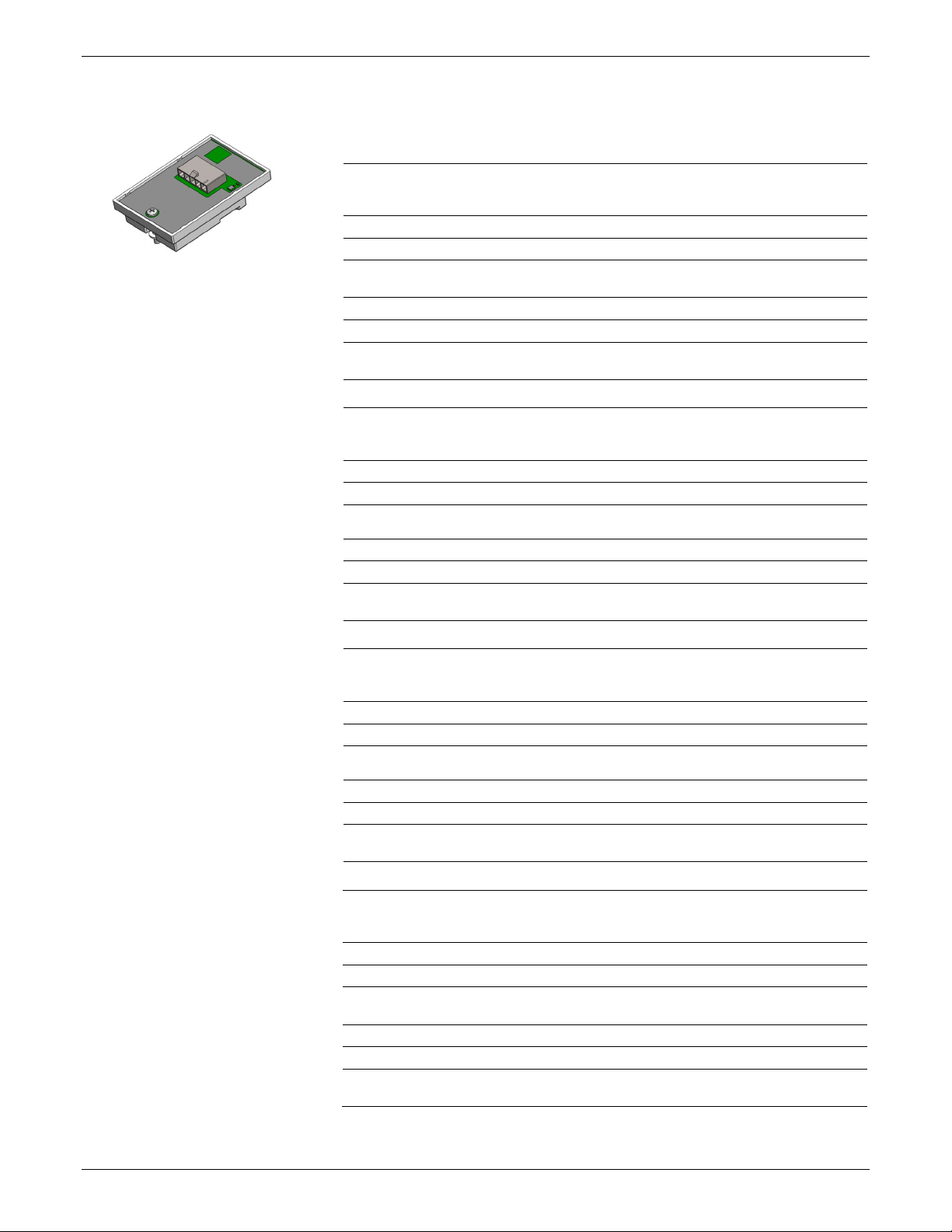
Optional Water Level Sensor Module (RXMOD
Pressure (Absolute) and Water Level Measurements
Operation Range
Factory Calibrated Range
Burst Pressure
Water Level Accuracy*
Raw Pressure Accuracy**
Resolution
Pressure Response Time
(90%)***
Pressure (Absolute) and Water Level Measurements
Operation Range
Factory Calibrated Range
Burst Pressure
Water Level Accuracy*
Raw Pressure Accuracy**
Resolution
Pressure Response Time
(90%)***
Pressure (Absolute) and Water Level Measurements
Operation Range
Factory Calibrated Range
Burst Pressure
Water Level Accuracy*
Typical error: ±0.05% FS, 3.8 cm (0.125 ft) water
Raw Pressure Accuracy**
Resolution
Pressure Response Time
(90%)***
Pressure (Absolute) and Water Level Measurements
Operation Range
Factory Calibrated Range
Burst Pressure
Water Level Accuracy*
Raw Pressure Accuracy**
Resolution
Pressure Response Time
(90%)***
Module Specifications (continued)
-W1)
MX2001-01-SS-S and MX2001-01-Ti-S
Water Level Sensor Module
(RXMOD-W1)
0 to 207 kPa (0 to 30 psia); approximately 0 to 9 m (0 to 30 ft) of
310 kPa (45 psia) or 18 m (60 ft) depth
Typical error: ±0.05% FS, 0.5 cm (0.015 ft) water
<0.02 kPa (0.003 psi), 0.21 cm (0.007 ft) water
0 to 400 kPa (0 to 58 psia); approximately 0 to 30.6 m (0 to 100 ft) of
500 kPa (72.5 psia) or 40.8 m (134 ft) depth
<0.04 kPa (0.006 psi), 0.41 cm (0.013 ft) water
water depth at sea level, or 0 to 12 m (0 to 40 ft) of water at 3,000 m
(10,000 ft) of altitude
69 to 207 kPa (10 to 30 psia), 0° to 40°C (32° to 104°F)
Maximum error: ±0.1% FS, 1.0 cm (0.03 ft) water
±0.3% FS, 0.62 kPa (0.09 psi) maximum error
<1 second at a stable temperature
MX2001-02-SS-S
water depth at sea level, or 0 to 33.6 m (0 to 111 ft) of water at
3,000 m (10,000 ft) of altitude
69 to 400 kPa (10 to 58 psia), 0° to 40°C (32° to 104°F)
Typical error: ±0.05% FS, 1.5 cm (0.05 ft) water
Maximum error: ±0.1% FS, 3.0 cm (0.1 ft) water
±0.3% FS, 1.20 kPa (0.17 psi) maximum error
<1 second at a stable temperature
MX2001-03-SS-S
0 to 850 kPa (0 to 123.3 psia); approximately 0 to 76.5 m (0 to 251 ft)
of water depth at sea level, or 0 to 79.5 m (0 to 262 ft) of water at
3,000 m (10,000 ft) of altitude
69 to 850 kPa (10 to 123.3 psia), 0° to 40°C (32° to 104°F)
1,200 kPa (174 psia) or 112 m (368 ft) depth
Maximum error: ±0.1% FS, 7.6 cm (0.25 ft) water
±0.3% FS, 2.55 kPa (0.37 psi) maximum error
<0.085 kPa (0.012 psi), 0.87 cm (0.028 ft) water
<1 second at a stable temperature
MX2001-04-SS-S and MX2001-04-Ti-S
0 to 145 kPa (0 to 21 psia); approximately 0 to 4 m (0 to 13 ft) of
water depth at sea level, or 0 to 7 m (0 to 23 ft) of water at 3,000 m
(10,000 ft) of altitude
69 to 145 kPa (10 to 21 psia), 0° to 40°C (32° to 104°F)
310 kPa (45 psia) or 18 m (60 ft) depth
Typical error: ±0.075% FS, 0.3 cm (0.01 ft) water
Maximum error: ±0.15% FS, 0.6 cm (0.02 ft) water
±0.3% FS, 0.43 kPa (0.063 psi) maximum error
<0.014 kPa (0.002 psi), 0.14 cm (0.005 ft) water
<1 second at a stable temperature
1-508-759-9500 (U.S. and International) 4 www.onsetcomp.com
1-800-LOGGERS (U.S. only)
Page 5
HOBO RX3000 Remote Monitoring Station Manual
Water Level Sensor and Cable
Dimensions
Weight
Materials
Environmental Rating
Barometric Pressure (RXMOD
Operation Range
Temperature Calibrated
Range
Accuracy
Water Level Accuracy*
Resolution
Response Time
Stability (Drift)
Temperature (Water Level Sensors MX2001
Operation Range
Accuracy
Resolution
Response Time (90%)
Stability (Drift)
Module Specifications (continued)
Sensor (MX2001-0x-SS-S and MX2001-0x-Ti-S): 2.54 cm (1.0 inches)
Stainless sensor (MX2001-0x-SS-S): Stainless steel housing, Viton
IP68; cable is waterproof for continuous immersion up to 112 m
66 to 107 kPa (9.57 to 15.52 psia)
±0.2 kPa (±0.029 psi) over full temperature range at fixed pressure;
Typical error: ±0.075% FS, 0.3 cm (0.01 ft) water
<0.01 kPa (0.0015 psi)
<1 second at stable temperature
<0.01 kPa (0.0015 psi) per year
diameter, 9.91 cm (3.9 inches) length
Cable (CABLE-RWLMOD-xxx): 0.47 cm
diameter, 0.2 to 400 m (0.65 to 1,312 ft) length
Note: The length of the water level logger cable can vary -0% to +3%
+10 cm (3.9 inches) from the length ordered.
Stainless sensor (MX2001-0x-SS-S): Approximately 141.4 g (4.99 oz)
in air; approximately 93.4 g (3.3 oz) in fresh water
Titanium sensor (MX2001-0x-Ti-S): Approximately 80 g (2.83 oz) in
air; approximately 37 g (1.3 oz) in fresh water
Cable (CABLE-RWLMOD-XXX): 39 g (1.38 oz) per 1 meter (3.28 ft)
and Buna-N O-rings, ceramic sensor in stainless steel end cap
Titanium sensor (MX2001-0x-Ti-S): Acetal housing, Viton and BunaN O-rings, ceramic sensor in Titanium end cap
Cable (CABLE-RWLMOD-XXX): Polycarbonate end cap, PVC end cap,
nylon collar nut, Viton O-rings, polyurethane jacket
(368 ft), refer to sensor model specifications for sensor depth rating
-W1)
-20° to 50°C (-4° to 122°C)
maximum error ±0.5% FS
Maximum error: ±0.15% FS, 0.6 cm (0.02 ft) water
±0.03 (0.185 inches ±0.01)
Plot A
1-508-759-9500 (U.S. and International) 5 www.onsetcomp.com
1-800-LOGGERS (U.S. only)
-0x-SS-S and MX2001-0x-Ti-S)
-20° to 50°C (-4° to 122°F)
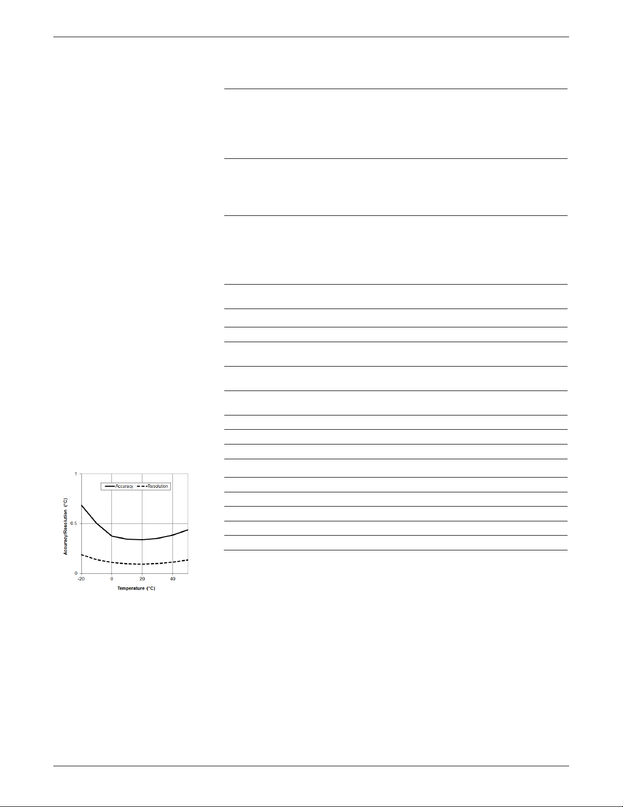
±0.44°C from 0° to 50°C (±0.79°F from 32° to 122°F), see Plot A
0.1°C at 25°C (0.18°F at 77°F), see Plot A
5 minutes in water (typical)
0.1°C (0.18°F) per year
* Water Level Accuracy: With accurate reference water level measurement, known water density,
and a stable temperature environment. System Water Level Accuracy equals the sum of the
Barometric Water Level Accuracy plus the selected sensor Water Level Accuracy.
** Raw Pressure Accuracy: Absolute pressure sensor accuracy includes all sensor drift, temperature,
and hysteresis-induced errors.
*** Changes in Temperature: Allow 20 minutes in water to achieve full temperature compensation of
the pressure sensor. There can be up to 0.5% of additional error due to rapid temperature changes.
Measurement accuracy also depends on temperature response time.
Page 6
HOBO RX3000 Remote Monitoring Station Manual
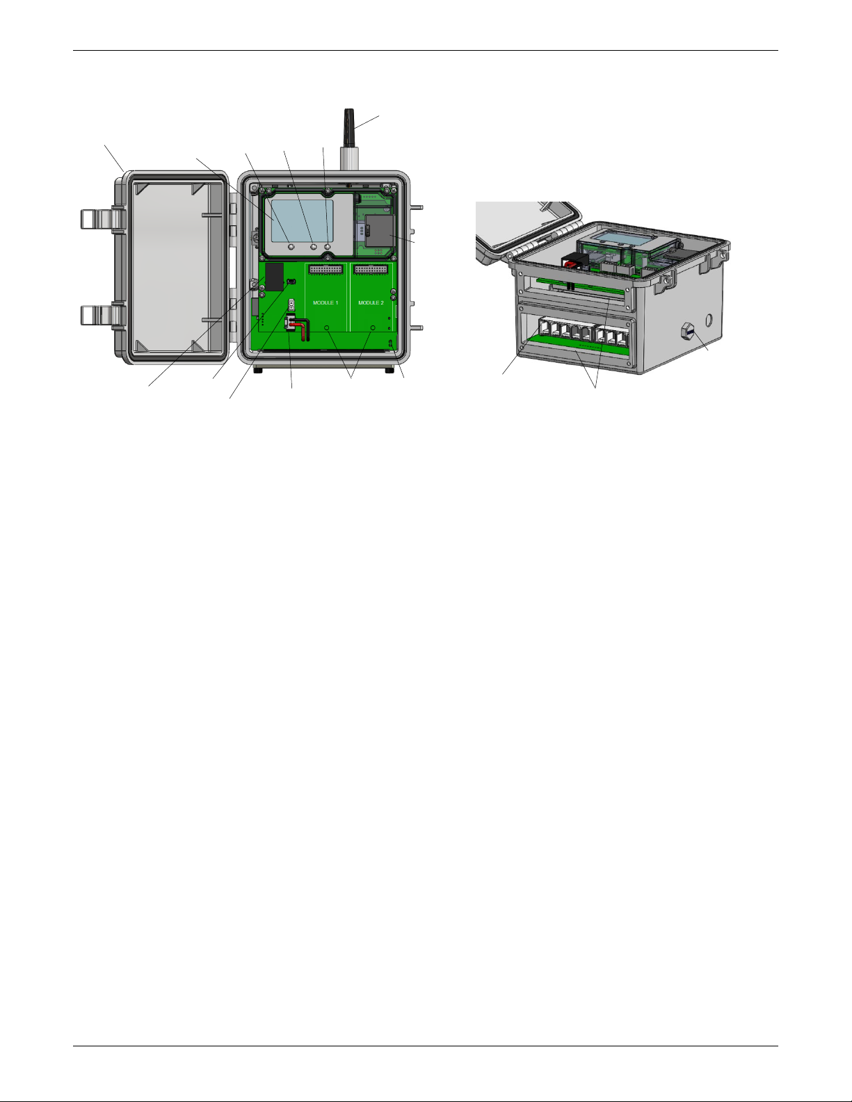
Battery Port
Smart Sensor
Cable Access Openings
Vent
SIM Card
LCD Screen
Ethernet
(RX3001)
Charging Port
USB Port
Module Slots
Station Door
Antenna
Grounding
Wire Port
Connect/
Start/
Button
Select
Button
Device Components and Operation
(RX3003)
Connector
Stop
Search
Button
Station Door: This is the protective, hinged door covering the
LCD and electronics. The station serial number and device key
needed for HOBOlink registration are located on the inside of
the door.
LCD Screen: This shows details about system, module, and
sensor operation (see LCD Operation).
Select Button: Use this button to cycle through information
about the smart sensors and optional modules (see LCD
Operation).
Start/Stop Button: Use this button to start and stop logging or
clear a fault code (see LCD Operation).
Connect/Search Button: Use this button to connect to
HOBOlink or search for new smart sensors (see LCD Operation).
Antenna: This is the external radio antenna for cellular
communication in the RX3003 model. The RX3002 and RX3004
models use an internal antenna.
SIM Card/Micro SIM Card: A SIM card is installed in the RX3003
model or a micro SIM card is installed in the RX3004 model to
enable cellular communications.
Grounding Wire Port: Use this port to connect a grounding wire
(see Deploying and Mounting the Station).
Module Slots: These are two slots for installing optional analog
sensor, relay, water level sensor, or RXW Manager modules
(see Setting up the Station).
(RX3003) or
Micro SIM Card
(RX3004)
Connectors
Battery Port: Use this port to plug in the internal battery cable
(see Setting up the Station and Battery Information).
Charging Port: Use this port to plug in an AC adapter, solar
panel, or external power source to keep the battery charged
(see Setting up the Station and Battery Information).
USB Port: Use this port to connect the station to the computer
via USB cable as needed for HOBOware.
Ethernet Connector: Use this port to connect an Ethernet RJ45
cable for the RX3001 model (see Setting up the Station).
Smart Sensor Connectors: Use these input jacks to connect up
to 10 smart sensors (see Setting up the Station). The station can
support up to 15 smart sensor data channels; some smart
sensors have more than one data channel.
Cable Access Openings: These are the two openings for
connecting cables and wires to the station (see Setting up the
Station). Install the cover plates and rubber cable channels in
these openings to create a weatherproof seal (see Deploying
and Mounting the Station).
Vent. This vent allows pressure to equalize inside the station
while keeping water out. Note that the pressure inside the
station does not match the outside air pressure exactly.
Therefore, a barometric pressure sensor deployed within the
case cannot measure the true atmospheric pressure unless it
has its own unrestricted vent to the outside.
1-508-759-9500 (U.S. and International) 6 www.onsetcomp.com
1-800-LOGGERS (U.S. only)
Page 7
HOBO RX3000 Remote Monitoring Station Manual
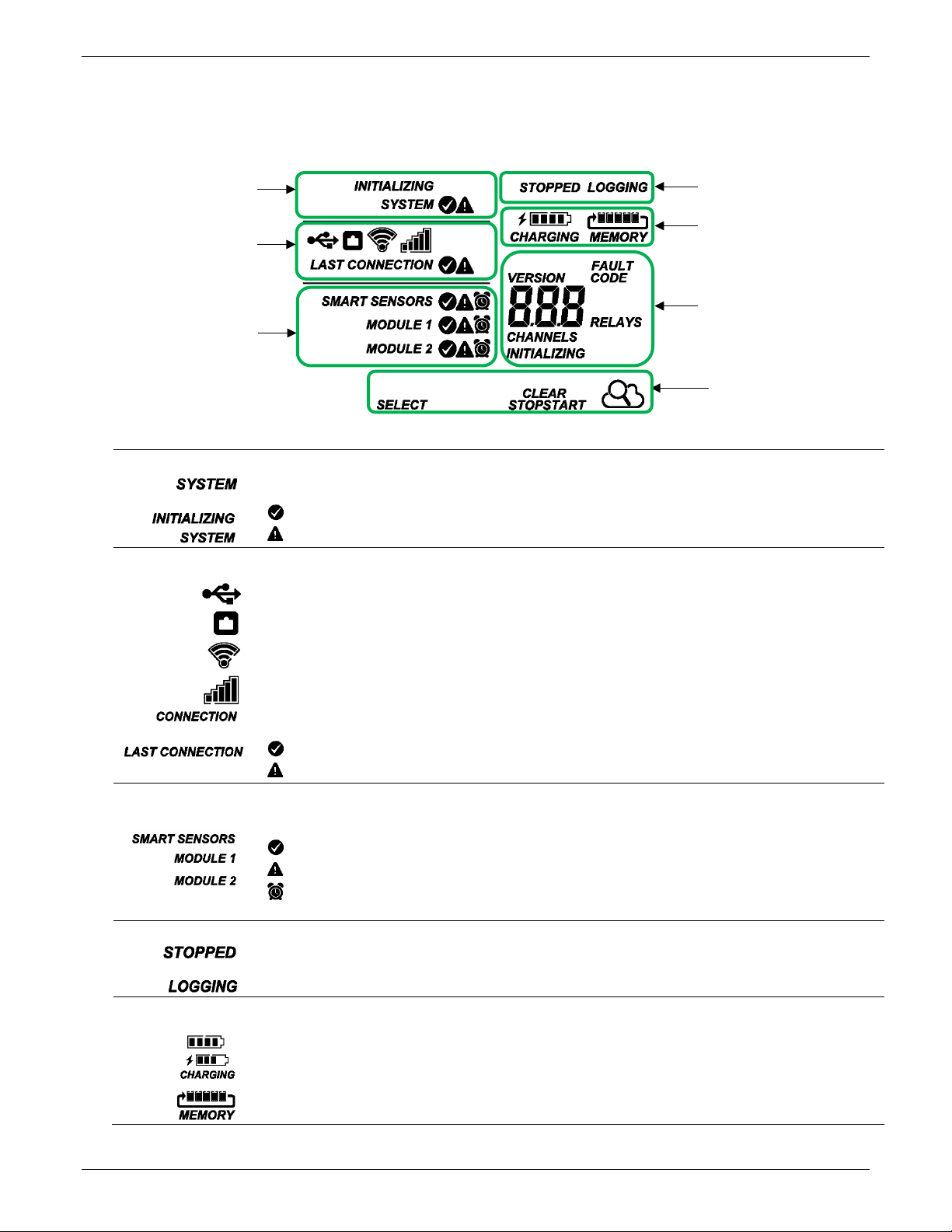
System Status
When the station is powered up, “Initializing System” flashes in the upper left part of the LCD. After initialization is
Connection Status
This part of the LCD shows the communication method used for connecting to HOBOlink and the system connection
status.
This indicates the station is using Wi-Fi to connect to HOBOlink. This also shows the strength of the wireless signal; the
more bars there are, the stronger the signal. This will blink while connecting to HOBOlink.
indicates there was a problem with the last connection; check the Connections log in HOBOlink.
Smart Sensor and
This part of the LCD shows the status of the smart sensors and any optional modules installed. Module 1 is installed in the
One of the following symbols will also appear next to smart sensors or a module (if applicable):
Logging Status
Battery and
Memory Status
This part of the LCD shows the current battery level and memory.
The battery indicator shows the approximate battery power remaining. In this example, the battery is fully charged. The
When the station is logging, it will record data indefinitely, with newest data overwriting the oldest data until the station is
System Status
Connection Status
Smart Sensor and
Logging Status
Battery and Memory Status
Channel and Device
Button Symbols
LCD Operation
This example shows all symbols illuminated on the LCD screen with an overview of what each section of the LCD represents. Refer to the
table below for details about each section and associated symbols.
Information
Module Status
This part of the LCD shows the overall system status.
complete, “System” remains illuminated and one of these symbols will appear:
or
indicates the system is ok.
indicates there is a problem with the system; check the Device Information panel on your station page in HOBOlink.
Module Status
This indicates the station is connected via a USB cable.
This indicates the station is using Ethernet to connect to HOBOlink. This will blink while connecting to HOBOlink.
This indicates the station is using a cellular network to connect to HOBOlink. This also shows the strength of the cellular
signal; the more bars there are, the stronger the signal. This will blink while connecting to HOBOlink.
When the station is attempting to connect or is currently connected to HOBOlink, “Connection” flashes on the LCD. After
the connection is complete, “Last Connection” remains illuminated and one of these symbols will appear:
or
indicates the last connection to HOBOlink was ok.
left slot and Module 2 in the right slot.
indicates the smart sensor or module is ok.
indicates there is a problem with the smart sensor or module; check your device page in HOBOlink.
indicates a sensor alarm has tripped and will flash on the LCD until the alarm is cleared; check the Alarms log in
HOBOlink.
This part of the LCD indicates whether the station is currently logging.
“Stopped” indicates the station is not currently logging while “Logging” indicates it is currently logging. Press the
Start/Stop button to start or stop logging as desired. Note that “Logging” will blink until the first data point is logged after
or
the Start button is pressed.
or
lightning bolt will appear when an AC adapter, solar panel, or external power source is plugged into the station. “Charging”
will flash while the battery is being charged.
stopped. This continuous logging is represented by the arrow in this symbol.
1-508-759-9500 (U.S. and International) 7 www.onsetcomp.com
1-800-LOGGERS (U.S. only)
Page 8
HOBO RX3000 Remote Monitoring Station Manual
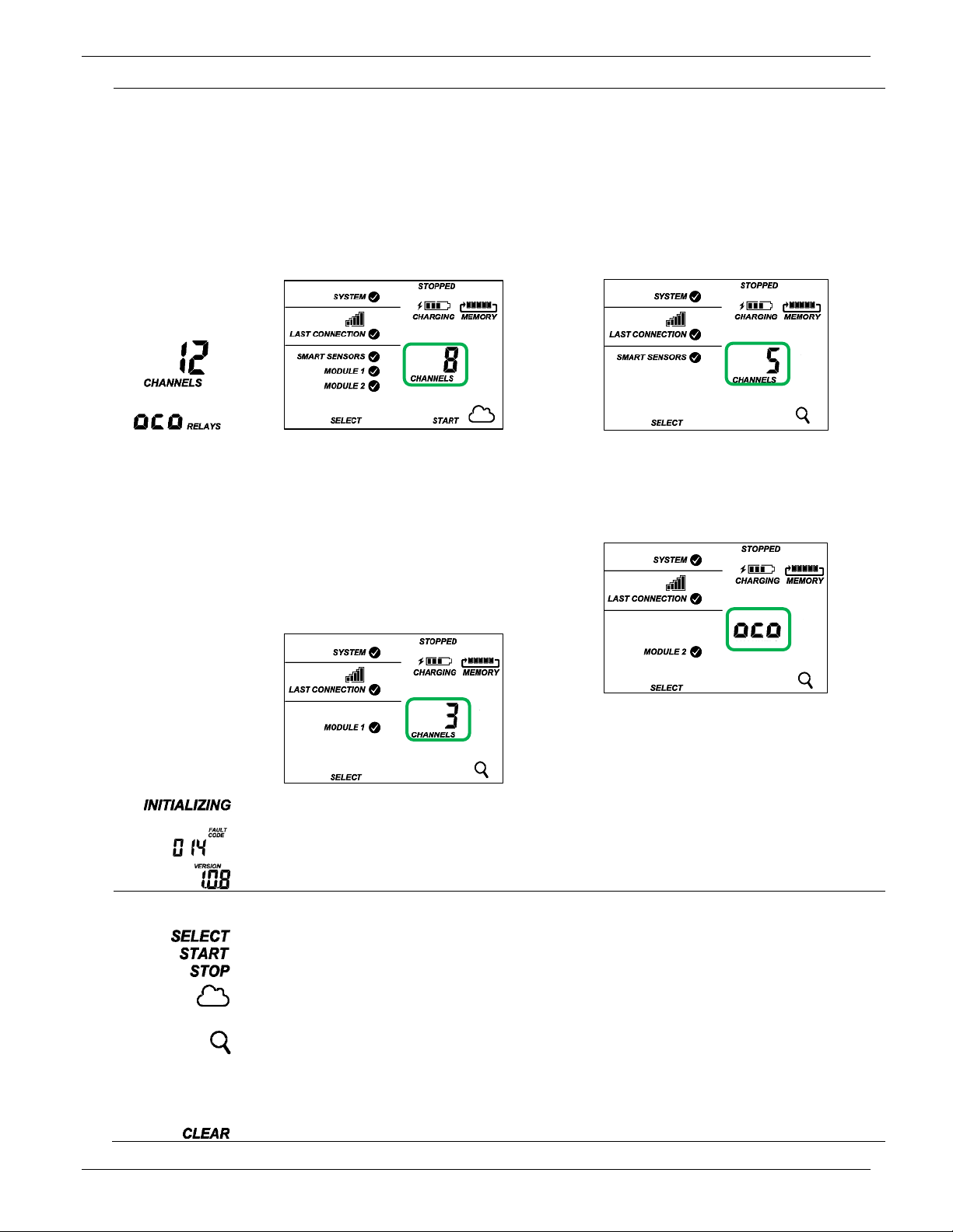
Channel and
This part of the LCD shows the number of channels and other information about each module. It also shows general device
This is a numerical code that appears when a system fault has occurred. You may need to provide this code to Onset
This is the version number of the station firmware. It only appears when powering up the device.
Button Symbols
Press this button to cycle through status information about the smart sensors and two optional modules.
Press this button to start logging. This option is not available while the station is actively connected to HOBOlink.
Press this button to connect to HOBOlink. This option is only available on the main LCD screen. It is not available when
a connection is underway or active.
Use this button to clear a fault code.
Device
Information
or
information. Press the Select button to scroll through four screens: the main screen, smart sensors screen, Module 1, and
Module 2 screens.
Main Screen
When viewing the main LCD screen, the total number of
channels in use by the system is displayed. This is a
combination of smart sensor channels and enabled
sensor channels. For example, if there are 5 smart sensor
channels and 3 analog sensor channels, then 8 channels
are shown on the main screen, as in the following
example.
Smart Sensors Screen
When viewing the smart sensors screen, the number of smart
sensor channels is displayed. Note that some smart sensors
have more than one channel associated with them so the
number of channels may not match the number of physical
smart sensors. In this example, there are 5 smart sensor
channels.
Module 1 and 2
When viewing the Module 1 or Module 2 screen,
information about that particular module is displayed. If
an analog sensor module is installed, the number of
enabled analog sensors is displayed in the channels count
(three sensors in this example). If an RXW Manager
module is installed, the channel count represents all
measurement channels plus a battery channel for each
mote in the HOBOnet RX Wireless Sensor Network. For
example, one temp/RH wireless sensor has a channel
count of three as shown below: two for temperature and
RH and one for the mote battery.
When a relay module is installed, the state of each relay is
shown on the module screen. In this example, a relay module
is installed in the Module 2 slot so this shows whether each
relay is open “o” or closed “c”. In this example, the first and
third relays are open, and the second one is closed.
If a water level sensor module is installed, the channel count is
listed as 4. This represents barometric pressure, water
pressure, differential pressure, and water temperature. Water
level and water flow channels are derived in HOBOlink and not
included in the channel count shown on the station LCD.
This will blink in the lower right part of the LCD when a firmware update is underway. It will display which module or
element is being updated.
Technical Support. See Troubleshooting for details.
Use the three buttons below the following symbols to operate the station. Press any of the three buttons to turn on the
LCD.
Press this button to stop logging. This option is not available while the station is actively connected to HOBOlink.
scrolling through smart sensor and module information with the Select button. In addition, this option is not available while
Press this Search button for the station to detect all currently installed smart sensors or to add motes to your HOBOnet RX
Wireless Sensor Network. As you add or remove smart sensors while the station is stopped, press the Select button and
then the Search button for the system to recognize your changes. This option is not available for smart sensors while the
station is logging. To add motes to the HOBOnet RX Wireless Sensor Network, press the Select button to switch to the
module for the RXW Manager and then press the Search button for the station to find the motes. The station can search for
motes whether it is logging or stopped.
1-508-759-9500 (U.S. and International) 8 www.onsetcomp.com
1-800-LOGGERS (U.S. only)
Page 9
HOBO RX3000 Remote Monitoring Station Manual
Connect the battery cable here
Plug in an AC adapter
or solar panel here
Insert the connectors
Tighten the screw on installed modules
Notes on LCD Operation:
• The LCD will turn off after 5 minutes of inactivity. Press
any button to turn the LCD back on.
• There can be a delay before the LCD updates. For
example, if you plug in an AC adapter, it may take a few
seconds before the lightning bolt icon appears on the
LCD. This delay is by design to preserve battery life.
Setting up the Station
Follow these steps to set up the station.
1. Log in to HOBOlink.
Go to www.hobolink.com and log in to an existing account
or create a new one. You’ll receive an email to activate the
new account.
2. Register the station.
In HOBOlink, click Devices, RX Devices, and then the
Register a Device link. Give the station a name and enter
the serial number and device key from the label inside the
station door.
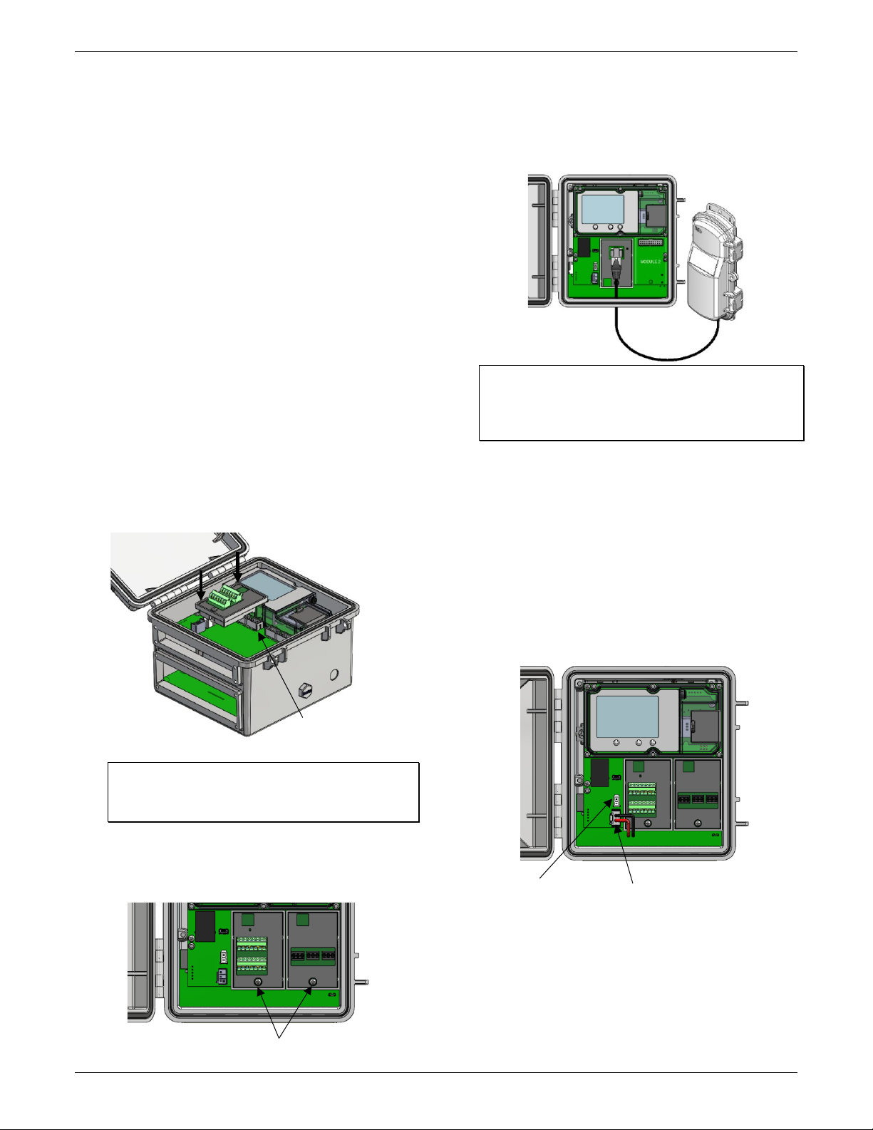
3. Install optional modules or user-supplied SIM.
a. Make sure the station is powered down (unplug any
charging device and then disconnect the battery).
b. Insert the connector on the back of the module into the
receptacle in the left or right module slot. Add a second
module to the other slot if desired.
If you installed an RXW Manager module:
Plug the cable from the RXW Manager mote into the jack on
the module, making sure the cable is inserted through the
bottom of the station case. Do not reconnect the power on
the station until the mote is plugged in as shown.
WARNING: If you inadvertently install modules while the
power is on, you must disconnect and then reconnect the
battery and charging device to guarantee proper
operation.
If you are installing your own SIM:
Before continuing, follow the instructions at
https://www.onsetcomp.com/support/ manuals/installingsim-rx3000-station.
4. Plug in the battery and charging device.
a. Plug in the battery cable.
b. Feed the AC adapter or solar panel cable through the
smaller of the two cable openings and plug it in. You can
also use an optional external DC power cable (CABLERX-PWR) with your own powering device in place of the
AC adapter or solar panel.
Tip: Install the analog module, water level sensor, or
RXW Manager module on the left and the relay module
on the right for easier cable routing.
3. Using a Phillips-head screwdriver, tighten the screw at
the bottom of each module. In this example, an analog
module is installed in the Module 1 slot and a relay
module is installed in the Module 2 slot.
1-508-759-9500 (U.S. and International) 9 www.onsetcomp.com
1-800-LOGGERS (U.S. only)
on the module here
Page 10
HOBO RX3000 Remote Monitoring Station Manual
“Initializing
A checkmark
Plug in an Ethernet cable here
A checkmark
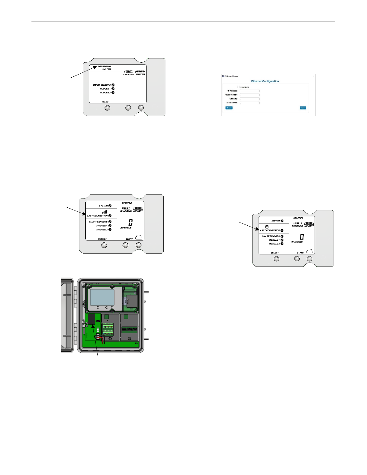
c. Once the battery cable is plugged in, “Initializing
System” will flash on the LCD. A checkmark appears next
to “System” after the station initialization is complete.
System”
flashes when
the battery
cable is first
plugged in
5. Check and configure device communications.
For RX3003 and RX3004 cellular models:
After the station powers up in the previous step, it will
connect to HOBOlink automatically within two minutes. The
cellular icon and “Connection” will flash while the
connection is underway. Once the connection is complete, a
checkmark appears next to Last Connection. Note that the
entire initialization process may take several minutes; wait
until Last Connection and the checkmark appears before
continuing to step 6.
appears next to
Last Connection
after connecting
to HOBOlink
For RX3001 Ethernet models:
a. Plug in an Ethernet cable.
b. The station uses DHCP by default. If your network uses
DHCP, skip to step i.
If your network uses static IP addresses, connect the
station to the computer with the USB cable. (Consult
your Network Administrator if you are unsure whether
your network uses static IP addresses or for help with
the following steps).
c. In HOBOware, select Manage RX Station from the
Device menu. (On a computer with Microsoft®
Windows®, you may see a warning that Windows
Firewall has blocked some features. Select Domain
networks and click Allow Access.)
d. In the RX Station Manager, click the Actions button and
select Network Access.
e. Deselect the Use DHCP checkbox.
f. Enter the IP Address, Subnet Mask, Gateway, and DNS
Server. Consult your Network Administrator for the
appropriate addresses to complete these fields.
g. Click Save in the RX Station Manager. Click Done and
then close the RX Station Manager.
h. Disconnect the USB cable.
i. Press the Connect button on the station (the cloud
should be visible on the LCD screen) to connect to
HOBOlink. The Ethernet icon and “Connection” will flash
while the connection is underway. Once the connection is
complete, a checkmark appears next to Last Connection.
Wait for the checkmark and then continue to step 6.
appears next to
Last Connection
after connecting
to HOBOlink
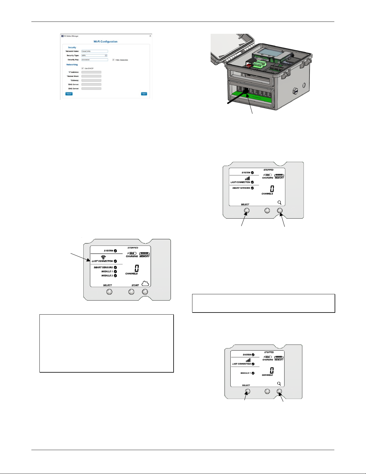
For RX3002 Wi-Fi models:
a. Connect the station to the computer with the USB
cable.
b. In HOBOware, select Manage RX Station from the
Device menu. (On a computer with Microsoft®
Windows®, you may see a warning that Windows
Firewall has blocked some features. Select Domain
networks and click Allow Access.)
c. In the RX Station Manager, click the Actions button and
select Network Access.
d. Enter the Security information for your Wi-Fi network.
Type the Network Name, select the Security Type, and
type the Security Key. Select the Hide characters
checkbox to hide any characters typed into the Security
Key field. Consult your Network Administrator or
wireless router documentation for help with
determining your network security type.
1-508-759-9500 (U.S. and International) 10 www.onsetcomp.com
1-800-LOGGERS (U.S. only)
Page 11
HOBO RX3000 Remote Monitoring Station Manual
Press the Select button to view
Press the Search button for the station
Plug in smart sensors here
A checkmark
Press the Search button for the
Press the Select button to switch to the
e. The station uses DHCP by default. If your network uses
DHCP, skip this step.
If your network uses static IP addresses, deselect the
Use DHCP checkbox. Enter the IP Address, Subnet Mask,
Gateway, and DNS Server. Consult your Network
Administrator if you are unsure whether your network
uses static IP addresses or for the appropriate addresses
to enter in this fields.
b. Press the Select button to view the smart sensors on the
LCD and then press the Search button (the magnifying
glass icon should be visible as in the following example).
The station will search for all connected smart sensors
and show the number of channels after a few seconds.
f. Click Save in the RX Station Manager. Click Done and
then close the RX Station Manager.
g. Disconnect the USB cable.
h. Press the Connect button on the station (the cloud
should be visible on the LCD screen) to connect to
HOBOlink. The Wi-Fi icon and “Connection” will flash
while the connection is underway. Once the connection
is complete, a checkmark appears next to Last
Connection. Wait for the checkmark and then continue
to step 6.
the smart sensor screen
to find all connected smart sensors
appears next to
Last Connection
after connecting
to HOBOlink
6. Plug in and search for any smart sensors.
Important: If this RX3000 station is a replacement for an
existing U30 station, it is imperative that you power down
the U30 station being replaced (disconnect the battery
and AC adapter or solar panel) before you remove the
smart sensors and connect them to the RX3000. Do not
repower the U30 station or allow it to connect to
HOBOlink again unless at least one different smart sensor
is connected to the U30 station first.
a. Feed the smart sensor cable for one smart sensor
through the larger of the two cable openings and plug it
into one of the 10 smart sensor connectors. Repeat for
any additional smart sensors.
Note that some smart sensors have more than one
channel associated with them so the number of
channels may not match the physical number of smart
sensors connected (for example the temperature/RH
smart sensor has two channels: one for temperature
and one for RH).
7. Add any wireless sensor motes.
Important: Keep the mote(s) near the RX3000 station while
completing these steps.
a. Press select to switch to the module where the RXW
Manager is installed (Module 1 or Module 2) and then
press the Search button to wait for motes to join the
network.
module with RXW Manager installed
station to search for motes to join
1-508-759-9500 (U.S. and International) 11 www.onsetcomp.com
1-800-LOGGERS (U.S. only)
Page 12

HOBO RX3000 Remote Monitoring Station Manual
J1
J2
This signal strength icon
a network.
Once a network is found,
left to right.
c.
d.
This network connection “x”
to five minutes.
Once the mote has finished
a.
b.
Press this button for 3 seconds
Feed analog sensor,
b. Install the rechargeable batteries in the mote and press
the button on the mote for 3 seconds.
c. Watch the mote LCD during the process of joining the
network.
blinks while searching for
icon blinks while the mote
completes the registration
process, which may take up
the icon will stop flashing
and the bars will cycle from
joining the network, the “x”
icon is removed and the
channel count on the station
LCD increases by the number
of measurement channels
for the mote plus the
Note: If the mote cannot find the network or has
trouble remaining connected during this process, make
sure the mote is in a vertical, upright position and
within range of the station.
Repeat these steps to add other motes. Press the
Search button on the station when finished adding
motes.
Important: If you will be installing the weatherproof rubber
cable channel in the cable access opening as described in
Deploying and Mounting the Station, the cable diameter for
analog sensors or relay devices must be 4.0 mm (0.156 in.) to
fit through one of the smaller holes or 6.4 mm (0.25 in.) to fit
through one of the larger holes. If the cable diameter is too
small, build up the diameter using heat shrink. If the cable is
too big, splice on another cable with a smaller diameter to fit
through the hole. If you are using the rubber cable channel
designed for the water level sensor, reserve the medium
holes for the water level sensor cable.
To connect analog sensors:
You can connect a two- or three-wire sensor or transducer
to one of the four terminals in the analog module.
a. Loosen the screw for each pin on the screw terminal.
b. Feed the wire through the smaller of the two cable
access openings.
c. Insert the appropriate wire into the screw terminal (see
the pinout table below). The wire should be trimmed to
expose 0.25 inches ±0.04 inches of bare wire.
d. Tighten the screw.
e. Plug in the battery and then the charging device to
power up the station.
Analog Module Pinout Table
Pin # Pin Description
1 CH1 SIGNAL 1 CH3 SIGNAL
2 CH1 GND 2 CH3 GND
3 +12V Excitation 3 +12V Excitation
4 GND (EX. RTN) 4 GND (EX. RTN)
5 CH2 SIGNAL 5 CH4 SIGNAL
6 CH2 GND 6 CH4 GND
7 SHIELD 7 SHIELD
Pin # Pin Description
8. Connect analog sensors, relay devices, or water level sensors.
Note: You may wait to connect these until you are at the
deployment site.
Power down the station (unplug any charging device and
then disconnect the battery). Connect any sensors or
devices to the optional modules as described in the
following sections. Be sure to feed any cables or wires
through the smaller cable access opening shown below.
1-508-759-9500 (U.S. and International) 12 www.onsetcomp.com
1-800-LOGGERS (U.S. only)
relay, and water level
sensor cables through
this opening to
connect them to the
optional modules
Note: All four input channels share the same common ground.
Analog Module Functional Diagram
To connect relay devices:
You can connect up to three devices to the relay module.
The relays are only for low power switching. To switch to
higher power, use an appropriately rated relay and use the
station relay to switch the external relay on or off.
a. Loosen the screw for each pin on the screw terminal.
Page 13

HOBO RX3000 Remote Monitoring Station Manual
Pin Desc.
Pin Desc.
Pin Desc.
Press the Connect button
Press the Select button to
Insert this
Use one of these two medium holes
for the water level sensor cable
b. Feed the wire through the smaller of the two cable
access openings.
c. Insert the appropriate wire into the screw terminal (pins
1 and 2 are interchangeable, pin 3 is optional; see the
pinout table).
d. Tighten the screw.
e. Plug in the battery and then the charging device to
power up the station.
Relay Module Pinout Table
RELAY-1
1 Relay 1 Relay 1 Relay
2 Relay 2 Relay 2 Relay
3 Shield 3 Shield 3 Shield
RELAY-2
RELAY-3
To install a water level sensor:
a. Feed the water level sensor cable through the smaller of
the two cable access openings.
b. Insert the connector at the end of the cable into the
receptacle on the module as shown below. The
connector will snap into place once installed. Be careful
not to push, pull, or twist the cable while installing the
connector.
iv. Close the cable channel and press it into the opening.
v. Install the cover plate with loosely installed
thumbscrews.
vi. Lightly coat rubber plugs with a small amount of
grease and use them to fill the empty holes. Use one
of the rubber plugs included with the water level
sensor module to fill the empty medium hole. Use the
rubber plugs from the channel kit included with the
station to fill any remaining large and small holes.
Insert the thin part of the plug into the hole and push
it in until the thick part fills the hole.
vii. Tighten the thumbscrews on the cover plate.
viii. Repeat these steps with the large cable channel. See
Installing the Weatherproof Rubber Cable Channel
and Covers for additional details.
e. Insert the water level sensor cable jack into the water
level sensor. Screw on the locking nut (hand tight).
connector onto
the receptacle
on the module
c. Install any other sensors and cables that will be using the
top cable access opening.
d. Install the top rubber cable channel into the cable access
opening.
i. Use silicone grease to lightly coat all four outer edges
and the inside of the rubber cable channel shipped
with the water level sensor module (do not use the
small rubber cable channel shipped with the RX3000
station).
ii. Use the grease to lightly coat the portion of the water
level sensor cable that will be in the cable channel.
Repeat for all other cables.
iii. Position the cable channel around the cables, routing
the cables through the proper grooves. Use one of
the medium-sized holes shown below for the water
level sensor cable.
Important: Make sure the O-rings on the cable jack end
and the sensor mating housing surfaces are clear of any
debris. Any contamination of these surfaces can cause
leaks that may lead to sensor failure.
f. Plug in the battery and then the charging device to power
up the station.
9. Connect to HOBOlink.
Use the Select button to return to the main LCD screen that
shows all sensors and modules and then press the Connect
button (the cloud icon should be visible as shown in the
following example). This is necessary for HOBOlink to
identify the newly added sensors (it does not start logging;
this will be done later in this procedure). Note that analog
sensors will not be listed in the channels count on the LCD
until they are configured in HOBOlink in the next step.
1-508-759-9500 (U.S. and International) 13 www.onsetcomp.com
1-800-LOGGERS (U.S. only)
return to the main LCD screen
Page 14

HOBO RX3000 Remote Monitoring Station Manual
Or, you can choose a specific item
Use the Next button to save changes and
10. Configure the station in HOBOlink.
Select Devices, RX Devices, and then click the icon next
to your station. Use the configuration screens in HOBOlink
to finish setting up the station, starting with General
Configuration (the nickname, time zone, and image for the
station). Use the Next button to move from one
configuration screen to the next or use the left menu to
select a specific item to configure. Follow the steps in the
next subsections to configure the readout settings, smart
sensors, wireless sensors, and optional modules. Any
changes you make will take effect the next time the station
connects to HOBOlink. Note: Click Save or Next in any
screen to save your changes. You will lose any changes
made if you click Back without clicking Next or Save first.
move through each configuration screen
Smart Sensors Logging and Configuration
You can configure both the global settings that affect all smart
sensors (logging interval and sampling interval) and the settings
for each smart sensor (labels, graphs, and scaling).
a. Click Smart Sensors Logging from the menu on the left.
b. Select the logging interval. This will be used by all
configured smart sensors.
c. Enable the sampling interval and enter the rate to use in
minutes and seconds.
Tip: When a sampling interval is configured, the station
will take multiple measurements within a given logging
interval and then average them together to create a
single logged data point. This is only an option for the
following smart sensors that support measurement
averaging: temperature (S-TMB-M0xx), PAR (S-LIAM003), solar radiation (S-LIB-M003), barometric
pressure (S-BPA-CM10 and S-BPB-CM50), 4-20mA input
(S-CIA-CM14), 12-bit voltage input (S-VIA-CM14), and
FlexSmart TRMS module (S-FS-TRMSA-D). Disable the
sampling interval if none of your smart sensors support
measurement averaging to avoid unnecessary drain on
the battery power.
d. Click Save or click Next.
to configure from this menu
Readout Configuration
a. Set the connection interval, which is how often the
station will connect to HOBOlink. For the RX3003 and
R3004 cellular models, the minimum connection
interval depends on your communication plan.
b. If you wish to set up a second connection interval, select
the “Night mode” checkbox. Select when night mode
should begin and end and then enter the connection
interval you want to use during that part of the day.
(The night mode schedule can take effect any time
during the day; it does not have to be at night.) Use this
option to save data in your communications plan (if
applicable) or to conserve battery power at night when
solar charging is unavailable. You can view current plan
usage in the Device Information section on your
station’s page in HOBOlink.
c. Click Save or click Next.
e. Click a smart sensor from the menu.
f. Type a label for the smart sensor (optional) and click to
enable or disable the graph (enabled by default).
g. To set up scaling for the smart sensor, click the Enable
Scaling checkbox and fill in the Scaled Units, Multiplier,
Offset, and Scaled Measurement Type fields.
h. Click Save. You can also click Next to move from one
smart sensor to the next.
1-508-759-9500 (U.S. and International) 14 www.onsetcomp.com
1-800-LOGGERS (U.S. only)
i. Repeat steps e–h for any additional smart sensors you
need to configure.
Water Level Sensor Module Configuration
You can configure both the global settings that affect all
water level sensor channels (logging interval and sampling
Page 15

HOBO RX3000 Remote Monitoring Station Manual
interval) and the settings for each individual channel. The
water level sensor includes the following four channels that
automatically record data at each logging interval:
barometric pressure, water pressure, differential pressure,
and water temperature. You can also configure water level
and water flow channels that calculate data based on the
logged data from the four sensor channels and the values
you enter in HOBOlink.
a. Click Water Level Sensors Logging from the
Configuration menu.
b. Select the logging interval. This will be used by all
channels associated with this sensor.
c. Enable the sampling interval (if desired) and enter the
rate to use in minutes and seconds.
d. Click Save or Next.
To add labels or scaling:
a. Click Barometric Pressure from the Configuration menu.
b. Type a label for the channel (optional) and click to enable
or disable the graph (enabled by default).
c. To set up scaling for the channel, click the Enable Scaling
checkbox and fill in the Scaled Units, Multiplier, Offset,
and Scaled Measurement Type fields.
d. Click Save. Repeat steps a–d for Water Pressure, Diff
Pressure, and Water Temperature.
Wireless Sensor Configuration
You can configure both the global settings for the RXW
Manager module that affect all sensor motes (logging
interval) and the settings for each individual mote (labels,
enabled graphs, and scaling).
a. Click Module <#>: Wireless Sensors Logging from the
menu on the left.
b. Select the logging interval to be used for all wireless
sensors, which can be different than the one used for
smart sensors and analog sensors (if applicable).
c. Click Save or Next.
d. Click one of the motes from the menu under Module <#>:
Wireless Sensors Logging as shown in the following
example. Click the serial number or name for the mote,
not the measurement type.
e. Type a label for the mote (optional) and click to enable
the battery graph for the mote if desired. The label will
also automatically be applied to any mote sensors
without a default label.
f. Click Save or click to Next to move to either the next
mote (if it was a repeater) or the sensor measurement
type for that mote.
Important: Do not configure the water level and water flow
channels yet. Configure any other sensors or relays as
necessary, continue to step 11 to start logging, and then
obtain a water reference level reading in step 12.
1-508-759-9500 (U.S. and International) 15 www.onsetcomp.com
1-800-LOGGERS (U.S. only)
Page 16

HOBO RX3000 Remote Monitoring Station Manual
g. Click one of the mote measurement types from menu
under Module <#>: Wireless Sensors Logging as shown
in the following example
h. Type a label for the measurement type (optional) and
click to enable or disable the graph (enabled by default).
i. To set up scaling for the wireless sensor, click the Enable
Scaling checkbox and fill in the Scaled Units, Multiplier,
Offset, and Scaled Measurement Type.
j. Click Save or click Next.
k. Repeat steps d–j for any additional motes you need to
configure for the module.
Analog Module and Sensor Configuration
You can configure both the global settings for the analog
module that affect all connected analog sensors (logging
interval, statistics, and excitation) and the settings for each
individual analog sensor (enabled logging and graphs,
labels, sensor type, and scaling).
a. Click Module <#>: Analog Sensors Logging from the
menu on the left.
b. Select the logging interval to be used for all analog
sensors, which can be different than the one used for
smart sensors and wireless sensors (if applicable).
d. Enable “Use excitation power” if you want sensors to
use the 12 V DC excitation voltage provided by the
station. Select warmup and enter the seconds or
milliseconds (5 milliseconds to 120 seconds), or select
continuous. Note that the excitation power selected will
be used for all of the module’s configured sensors.
• With warmup, the station supplies excitation power,
12 V DC, for a brief period prior to each
measurement. This allows you to select the minimum
warm-up time needed to allow for sensor
stabilization while conserving battery power. For
example, if you specify a warm-up of one second and
set the logging interval for the module to one minute,
the station will power the external sensor for one
second, log a measurement, and then turn off the
excitation power for the next 59 seconds. Note that
the excitation mode is automatically set to
Continuous if the warmup time selected is within one
second of or greater than the logging or sampling
intervals.
• With continuous, the station supplies constant
excitation power to the sensor for the entire duration
of the deployment. Continuous mode is required if the
sensor needs more than two minutes of warm-up time.
Important: Continuous mode operation will greatly affect
battery operating life and is not recommended.
Note that excitation power will not be enabled until
logging begins (if “Logging” is blinking on the LCD, then
excitation is not being used).
e. Click Save. You can also click Next to move from one
analog channel to the next.
f. Click one of the four analog sensor channels from the
menu, such as Channel 1 shown in this example.
g. Select “Enable Graph” if you want the sensor data to be
graphed in HOBOlink.
h. Select “Enable this channel” if you want the station to
c. Click the Enable checkbox under Sampling Interval if you
want to log statistics. Enter the sampling interval to be
used for calculating the statistics (must be a factor of
the logging interval). Select the statistics to be logged:
minimum, maximum, average, and standard deviation.
The selected statistics will be calculated between each
logging interval at the sampling interval rate you select.
Each statistical value will then be logged at each logging
interval.
1-508-759-9500 (U.S. and International) 16 www.onsetcomp.com
1-800-LOGGERS (U.S. only)
record data for this channel. If the channel is not
enabled, then it will not be part of the channel count
shown on the LCD.
i. Type a label for the sensor (optional).
j. Select the sensor/input type, which is needed to set the
voltage or current range for the analog input.
k. Click the Enable Scaling checkbox and then enter the raw
and scaled unit values as defined in the sensor manual.
Type the scaled measurement type.
Page 17

HOBO RX3000 Remote Monitoring Station Manual
Press this button to start logging
“Logging”
begins
Channel count
l. Click Save. You can also click Next to move from one
channel to the next.
m. Repeat steps f–l for any additional analog sensors you
need to configure for the module.
Relay Module Configuration
a. Click one of the three relays from the menu on the left,
such as Relay 1 in the following example.
b. Type a label and select Open or Closed for the Normal
Relay State. The label can be used to show what Open
or Closed corresponds to in your system (for example,
“closed relay turns pump on”).
c. Select what should happen on the next connection with
the station: open relay, close relay, or leave it at its
current state.
d. Click Save or click Next.
e. Repeat steps a–d for any additional relays you wish to
configure.
Tip: Refer to Setting System and Sensor Alarms for details on
using sensor alarms to activate the relays.
11. Start logging.
After you have finished configuring all the settings in
HOBOlink, you can start logging when ready. Press the Start
button on the station to start logging. The station will
connect to HOBOlink (“Connection” will blink on the LCD)
and then logging will begin at the logging interval specified
for smart sensors and analog sensors (if applicable).
Once logging begins, “Logging” appears in the upper right
corner of the LCD as shown in the following example.
“Logging” will blink until the first logging sample is
recorded. At that point, it will stop blinking and remain
illuminated until logging is stopped. Also note that the
channels count on the LCD screen will be updated to
include any analog sensors that were enabled in HOBOlink.
appears
when logging
updated for any
enabled analog
sensors
Important: See Deploying and Mounting the Station for
installation steps and other deployment guidelines. If using
the station outdoors or in harsh indoor conditions, you
must install the sensor cable channels and the plates for
weatherproofing. This must be completed before
continuing to step 12 if you are using a water level sensor.
12. If you installed a water level sensor module and sensor, obtain a reference water level reading.
Make sure the water level sensor is deployed in its final
location and the station is logging. Take a reference level
reading, measuring the water level from your reference
point.
Important: Note the reference level reading as well as the
date and time it was taken.
13. If you installed a water level sensor module and
sensor, configure the water level and water flow
channels in HOBOlink.
Perform the following steps in the field in HOBOlink with a
mobile device to verify that the system is logging the
water level correctly while you are still at the station site.
Water Level Configuration
a. In HOBOlink, select Devices and then RX Devices and
click the icon next to your station.
b. Under the water level sensors module in the
Configuration menu, select Water Level.
You can also start logging from HOBOlink. Select Start/Stop
from the Configure menu in HOBOlink and click Start.
Logging will not begin until the next time the station
connects to HOBOlink. Press the Connect button on the
station to connect to HOBOlink at any time.
1-508-759-9500 (U.S. and International) 17 www.onsetcomp.com
1-800-LOGGERS (U.S. only)
Page 18

HOBO RX3000 Remote Monitoring Station Manual
next scheduled connection, press the Cloud button on the
station LCD to connect to HOBOlink immediately. Note that the
reference water level information entered in this step will not
affect data already stored in HOBOlink.
Viewing Data in HOBOlink
Data is uploaded to HOBOlink each time the device connects.
For a snapshot of the latest conditions, click Devices, then RX
Devices, and click the device name to view the readings from
the last connection for smart sensors and logged analog
sensors. You can also view any enabled graphs as shown in the
following example.
c. Click the checkbox to Enable Channel.
d. Click the checkbox to Enable Graph and type a label
(optional).
e. Enter the reference water level and date and time
noted in step 12.
• If the water level surface is below the reference
point, enter the reference water level as a negative
number.
• If the water level surface is above the reference
point, enter the reference water level as a positive
number.
See Setting Up Water Level and Water Flow Channels
in HOBOlink for example diagrams showing reference
points.
f. Select the appropriate water density.
g. Click Save.
Water Flow Configuration
a. Select Water Flow from the Configuration menu.
b. Click the checkbox to Enable Channel.
c. Click the checkbox to Enable Graph and type a label
(optional).
d. Choose the measurement method for water flow.
e. Enter the appropriate information for the method
selected. See Setting Up Water Level and Water Flow
Channels in HOBOlink for more details on water flow
measurement methods.
f. Click Save.
Water level and flow data will be calculated starting with the
next connection to HOBOlink. If you don’t want to wait for the
Logged data is saved in a database. You can export this data on
demand as needed or set up automatic exports that are
delivered to email and/or FTP addresses on a schedule you
specify.
To download and export data:
1. In HOBOlink, click Data and Exports.
2. Click Create New Export.
3. Follow the instructions on the screen to select the name,
format, time zone, and time frame, and then the devices
and sensors to include in the export. Reorder the sensors as
needed.
4. Click Save to keep these settings for future use or click
Export Data to export immediately.
To set up a scheduled data delivery:
1. Click Data and then click Data Delivery).
2. Click Create New Delivery.
3. Under General Settings, type the name of the delivery
schedule and the frequency of delivery. Enable the Active
checkbox. Select other settings if desired.
4. Under Select Data to Export, choose the name of the
custom data export you want to be delivered (or follow the
previous set of steps to set up a custom data export).
5. Under Data Destination, select FTP/SFTP or Email for the
delivery method and fill in the appropriate fields.
6. Click Save. Data will then be delivered on the schedule you
selected.
For more information on Data Delivery, see the HOBOlink Help.
See also HOBOlink Help for other ways to monitor your station,
including setting up a map or using dashboards.
1-508-759-9500 (U.S. and International) 18 www.onsetcomp.com
1-800-LOGGERS (U.S. only)
Page 19

HOBO RX3000 Remote Monitoring Station Manual
Tripped smart
Setting System and Sensor Alarms
You can set up both system and sensor alarms in HOBOlink.
System alarms can trip when there is a missed connection, the
battery is low, or if there is a smart sensor failure. With a
sensor alarm, you can configure an alarm to trip at one level
and clear at another.
System Alarms
To add a system alarm:
1. In HOBOlink, click Devices, then RX Devices, and find the
station you want to configure. Click the arrow next to
and select Alarm Configuration.
2. Click Edit System Alarms.
3. For Missed Connection alarms:
a. Under Communication, select the Missed Connection
checkbox.
b. Set the length of time for HOBOlink to wait after the
station has missed a connection before an alarm trips.
c. Select the action to be taken when this alarm trips: send
an email or text. Enter the details and then select “Send
on Clear Also” if you want an email or text when the
alarm clears as well.
Important: Standard data fees and text messaging rates
may apply when using text notifications. Onset does not
charge a fee or guarantee delivery of text alerts, which is
subject to your carrier’s service and location. See the
HOBOlink Help for additional details on alarm
notifications.
d. Click Add Action if you want multiple actions to be taken
when the alarm trips (for example send an email and a
text).
4. For Battery Low and Sensor Failure alarms:
a. Under Device, select the Battery Low and/or Sensor
Failure checkboxes.
b. Select how you want to be notified when these alarms
trip: by email or text. Enter the appropriate addresses
and then select “Send on Clear Also” if you want an
email or text when these alarms clear as well.
5. Click Add Action if you want multiple actions to be taken
when the alarm trips (for example send an email and a
text).
6. Click Save. Changes will take effect the next time the station
connects to HOBOlink.
Red alarm symbols will appear in HOBOlink when these alarms
trip (if enabled).
Note for wireless sensors: If a wireless sensor mote goes
offline from the network for 30 minutes, the station will
automatically connect to HOBOlink to report the missing mote
regardless of any alarm settings in place. Unless the mote has
no battery power, it will continue logging data even if it is
offline from the network. Once the mote is back online, any
logged data will be uploaded during regular connections to
HOBOlink. Note: Once a mote is back online, it enters recovery
mode as HOBOlink receives the data logged while it was offline.
During this period of recovery, data for that mote will
temporarily be unavailable for data delivery, dashboards, and
data feeds. See the HOBOlink help for additional details.
Sensor Alarms
To add a sensor alarm:
1. In HOBOlink, click Devices, then RX Devices, and find the
station you want to configure. Click the arrow next to
and select Alarm Configuration.
2. Click Add a Sensor Alarm.
3. Select the sensor.
4. Select whether the alarm should trip above or below a
value or within a range.
5. Enter the sensor reading(s) for the alarm threshold.
6. Enter the number of logged data points you want the
station to record before the alarm trips.
7. If you selected the alarm to trip above or below a specific
reading, then select when the alarm should clear: above or
below the same value or a different value. Enter the value if
necessary.
8. Select the action to be taken when the alarm trips: send an
email or text or close, open, or pulse one of the three relays
if a relay module is installed. For email or text, enter the
details and then select “Send on Clear Also” if you want an
email or text when the alarm clears as well.
Important: Standard data fees and text messaging rates
may apply when using text notifications. Onset does not
charge a fee or guarantee delivery of text alerts, which is
subject to your carrier’s service and location. See the
HOBOlink Help for additional details on alarm
notifications.
9. Click Add Action if you want multiple actions to be taken
when the alarm trips (for example, close the relay and send
an email).
10. Add any optional notes for this alarm.
11. Click Save. Changes will take effect the next time the station
connects to HOBOlink.
12. Repeat steps 2 through 11 for each additional sensor alarm
you want to add.
A red alarm symbol appears next to that sensor in HOBOlink
when it trips. An alarm symbol will also appear on the LCD.
sensor alarm
and analog
sensor alarm
1-508-759-9500 (U.S. and International) 19 www.onsetcomp.com
1-800-LOGGERS (U.S. only)
Page 20

HOBO RX3000 Remote Monitoring Station Manual
Setting up Water Level and Water Flow Channels in HOBOlink
If both a water level sensor module (RXMOD-W1) and water
level sensor are installed, the station will automatically log four
measurement channels:
• Barometric pressure
• Water pressure
• Differential pressure
• Water temperature
In addition, you can set up two additional channels in
HOBOlink:
• Water level
• Water flow
These derived channels are only available once enabled in
HOBOlink. The data for these two channels are calculated at
each logging interval based on the measurements from the
pressure and temperature channels and the settings and values
you enter in HOBOlink.
If a water level sensor is not physically connected to the
module, barometric pressure will be the only channel logged
related to the water level sensor. You will not be able to set up
water level and water flow unless you install the water level
sensor as described in Setting up the Station. Similarly, if you
unplug a water level sensor while a station is logging, only
barometric pressure will be logged and the rest of the water
level sensor channels will report errors.
Setting up a Water Level Channel
Important: Make sure the station has started logging and you
have taken a reference water level reading from the location
where the sensor is deployed with the date and time of the
reading before performing these steps.
To set up a water level channel:
1. In HOBOlink, select Devices and then RX Devices and click
the icon next to your station.
2. Under the water level module in the Configuration menu,
select Water Level.
3. Click the checkbox to Enable Channel.
4. Click the checkbox to Enable Graph and type a label
(optional).
5. Enter the reference water level and date and time the
reading was taken.
• If the water level surface is below the reference point as
shown below, enter the reference water level as a
negative number.
• If the water level surface is above the reference point as
shown below, enter the reference water level as a
positive number.
6. Select the appropriate water density for your deployment
location.
7. Click Save.
Water level will be calculated starting with the next connection
to HOBOlink. Note that the reference water level information
entered in this step will not affect any previously logged data. It
will only be use for data logged from the point of the next
connection to HOBOlink forward. If this is the first time that
water level has been configured for this station, then the data
stored will go back to the date and time of the reference water
level. If you make other updates to the reference water level,
then the data will only be updated from the time of the next
connection to HOBOlink.
Setting up a Water Flow Channel for a V-Notch Weir
If you are using a v-notch weir similar to the upper diagram
below along with the water level sensor, then HOBOlink can
calculate the flow rate for each water level reading using the
following two values that you enter:
• The notch (vertex) angle in degrees or radians, which is
represented as θ in the second diagram.
• The distance from the reference point to the v-notch
vertex, which is represented as WLv in the second
diagram. This value must be entered in the same units as
the reference water level you entered for the water level
channel (meters or feet).
1-508-759-9500 (U.S. and International) 20 www.onsetcomp.com
1-800-LOGGERS (U.S. only)
Page 21

HOBO RX3000 Remote Monitoring Station Manual
The HOBOlink water flow calculations for a v-notch weir
assume the following:
• The stilling well with the water level sensor should be
placed at a distance of at least 4 x hmax upstream of the
weir.
• In general, if the notch area is small relative to the area of
the approach channel, the weir is “fully contracted” and
these flow equations will work. More specifically, the ratio
of the channel width to the v-notch width should be
greater than 3, and the ratio of hmax/p should be less than
1. It may also work for weirs not meeting these guidelines
if the approach channel is smooth, straight, and
rectangular.
• The weir should be between 0.8 and 2 mm (0.03 and 0.08
inches) thick in the v-notch. If the bulk of the weir is
thicker than 2 mm (0.08 inches), the downstream edge of
the v-notch can be chamfered at an angle greater than 45°
(60° is recommended) to achieve the desired thickness of
the edges. Avoid water clinging to the downstream face of
the weir.
• The head height (h) must be no more than 35% of the
distance from the channel bottom to v-notch-vertex (P).
• The head height must be at least 6 cm (2.36 inches). When
the head height is less than 6 cm (2.36 inches), the flow
calculation will not be as accurate.
• The average width of the approach channel should be
greater than 91 cm (3 ft).
• The bottom of the v-notch should be at least 45 cm (1.5 ft)
above the bottom of the upstream channel.
• If the reference point is below the water level, then enter
a positive number.
8. Click Save.
Water flow will be calculated starting with the next connection
to HOBOlink.
Tip: It is good practice to set an alarm for the water level just
below the top of the v-notch so you know when the flow data is
close to exceeding its valid range. See Setting System and
Sensor Alarms.
Setting up a Water Flow Channel for a Rectangular Weir
If you are using a rectangular thin-plate weir similar to the
diagram below on the left along with the water level sensor,
then HOBOlink can calculate the flow rate for each water level
reading using four values that you enter. Note that these values
must be entered in the same units as the reference water level
you entered for the water level channel (meters or feet). The
values are:
• The notch width, which is represented as b in the second
diagram.
• The channel width, which is represented as B in the
second diagram.
• The notch height above the channel floor, which is
represented as P in the second diagram.
• The distance from the water level reference point to the
notch crest, which is represented as WLc in the second
diagram.
Important: Make sure the station has started logging and you
have configured the water level channel with a reference level
reading before performing these steps.
To set up a water flow channel using a v-notch weir:
1. Click Devices and then RX Devices, and find the station you
want to configure. Click the arrow next to the icon and
select Module/Sensor Configuration.
2. Under the water level module in the Configuration menu,
select Water Flow.
3. Click the checkbox to Enable Channel.
4. Click the checkbox to Enable Graph and type a label
(optional).
5. For the Measurement Method, select V-Notch Weir.
6. Enter the notch (vertex) angle of the weir in degrees or
radians.
7. For the “Water level at vertex,” enter the distance from the
reference point to the v-notch vertex in either meters or
feet (using the same reference point and units you used for
the reference water level in the water level channel).
• If the vertex is the reference point, then enter 0.
• If the reference point is the bottom of the channel, then
the value is represented as P in the diagram earlier in this
section.
• If the reference point is above the water level (such as
when using ground level as the reference point in a storm
sewer), then enter a negative number.
The HOBOlink water flow calculations for a rectangular weir
assume the following:
• The range for the weir opening width is 0.15 to 6 m (0.5 to
20 ft).
• The notch height (P) must be at least 0.1 m (0.33 ft).
• Either B = b (full-width weir) or B - b must be at least 0.2 m
(0.66 ft) (contracted weir).
• The weir should be between 1 to 2 mm (0.03 to 0.08
inches) thick in the opening. If the bulk of the weir is
thicker than 2 mm (0.08 inches), the downstream edge of
the opening can be chamfered at an angle greater than
45° (60° is recommended) to achieve the desired thickness
of the edges, and avoid water clinging to the downstream
face of the weir.
• The range for the head height (h) is 0.03 to 1.4 m (0.18 to
4.5 ft).
1-508-759-9500 (U.S. and International) 21 www.onsetcomp.com
1-800-LOGGERS (U.S. only)
Page 22

HOBO RX3000 Remote Monitoring Station Manual
• The range for the flow rate is from 3.45 to 17,188 l/s
(0.122 to 607 ft3/s).
• The value of h/p cannot be greater than 2.5.
• Water surface downstream of the weir should be at least
0.06 cm (2.36 inches) below the weir crest (i.e. below the
bottom of the opening).
Important: Make sure the station has started logging and you
have configured the water level channel with a reference level
reading before performing these steps.
To set up a water flow channel using a rectangular weir:
1. Click Devices and then RX Devices, and find the station you
want to configure. Click the arrow next to the icon and
select Module/Sensor Configuration.
2. Under Module 2: Water Level Sensors Logging on the left
menu, select Water Flow.
3. Click the checkbox to Enable Channel.
4. Click the checkbox to Enable Graph and type a label
(optional).
5. For the Measurement Method, select Rectangular Weir.
6. Enter the notch width in either meters or feet. Note: Use
the same units for this and all rectangular weir values as
you entered for the reference water level in the water level
channel.
7. Enter the channel width in either meters or feet.
8. Enter the notch height above the channel floor in either
meters or feet.
9. For the Distance from Water Level Ref Point to Notch, enter
the distance from the reference point to the notch crest in
either meters or feet.
• If the notch crest is the reference point, then enter 0.
• If the reference point is the bottom of the channel, then
the value is represented as P in the diagram earlier in this
section.
• If the reference point is above the water level (such as
when using ground level as the reference point in a
storm sewer), then enter a negative number.
• If the reference point is below the water level, then enter
a positive number.
10. Click Save.
Water flow will be calculated starting with the next connection
to HOBOlink.
Setting up a Water Flow Channel for a Trapezoidal Weir
If you are using a trapezoidal or Cipoletti thin-plate weir similar
to the diagram below on the left along with the water level
sensor, then HOBOlink can calculate the flow rate for each
water level reading using two values that you enter. Note that
these values must be entered in the same units as the
reference water level you entered for the water level channel
(meters or feet). The values are:
• The width at the base of the notch, which is represented
as b in the second diagram.
• The distance from the water level reference point to the
notch crest, which is represented as WLc in the second
diagram.
The HOBOlink water flow calculations for a trapezoidal weir
assume the following:
• The slopes of the notch sides must be 4 (vertical change /
horizontal change).
• Head height (h) should be measured at a distance of at
least 4 x hmax upstream of the weir.
• The weir should be between 1 to 2 mm (0.04 to 0.08
inches) thick in the opening. If the bulk of the weird is
thicker than 2 mm (0.08 inches), the downstream edge of
the opening can be chamfered at an angle greater than
45° (60° is recommended) to achieve the desired thickness
of the edges and avoid water clinging to the downstream
face of the weir.
• Water surface downstream of the weir should be at least
0.06 m (0.2 ft) below the weir crest (i.e. below the bottom
of the opening).
• The head height (h) must be at least 0.06 m (0.2 ft), but
less than b/3.
• The crest height above the channel floor (P) is measured
from the bottom of the upstream channel and should be
greater than 2 x hmax.
• “S” is measured from the sides of the channel and should
be greater than 2 x hmax.
Important: Make sure the station has started logging and you
have configured the water level channel with a reference level
reading before performing these steps.
To set up a water flow channel using a trapezoidal weir:
1. Click Devices and then RX Devices, and find the station you
want to configure. Click the arrow next to the icon and
select Module/Sensor Configuration.
2. Under Module 2: Water Level Sensors Logging on the left
menu, select Water Flow.
3. Click the checkbox to Enable Channel.
4. Click the checkbox to Enable Graph and type a label
(optional).
5. For the Measurement Method, select Trapezoidal Weir.
1-508-759-9500 (U.S. and International) 22 www.onsetcomp.com
1-800-LOGGERS (U.S. only)
Page 23

HOBO RX3000 Remote Monitoring Station Manual
6. Enter the notch width at the bottom in either meters or
feet, using the same units as you entered for the reference
water level in the water level channel.
7. For the Distance from Water Level Ref Point to Notch, enter
the distance from the reference point to the notch crest in
either meters or feet (using the same reference point and
units you used for the reference water level).
• If the notch crest is the reference point, then enter 0.
• If the reference point is the bottom of the channel, then
the value is represented as P in the diagram earlier in this
section.
• If the reference point is above the water level (such as
when using ground level as the reference point in a storm
sewer), then enter a negative number.
• If the reference point is below the water level, then enter
a positive number.
8. Click Save.
Water flow will be calculated starting with the next connection
to HOBOlink.
Setting up a Water Flow Channel for a General Flume
If you are using a flume along with the water level sensor, then
HOBOlink can calculate the water flow using a general flow
equation supported by a wide range of flumes that require only
one water level measurement to calculate flow, including ramp,
cutthroat, Parshall as well as broad-crested rectangular weirs.
The equation that HOBOlink uses is: Water Flow (Q) = C *
(Water Level - Head Offset)
or three water level measurements to calculate flow are not
supported.
For this equation to be accurate, there are constraints on the
flow conditions and flume design, including:
• Minimum and maximum flow rates
• Minimum and maximum head levels
• Ratio of the width of the weir/flume to the head
• Ratio of the height of the weir/flume to the head
• Location in the flume or weir for measuring the head.
The constraints depend on the type and characteristics of the
flume you are using, which can be obtained from the flume
manufacturer.
Important: Make sure the station has started logging and you
have configured the water level channel with a reference level
reading before performing these steps.
To set up a water flow channel using a general flume:
1. Click Devices and then RX Devices, and find the station you
want to configure. Click the arrow next to the icon and
select Module/Sensor Configuration.
2. Under the water level module in the Configuration menu,
select Water Flow.
3. Click the checkbox to Enable Channel.
4. Click the checkbox to Enable Graph and type a label
(optional).
5. For the Measurement Method, select General Flume.
n
. Flumes that require require two
6. For the Flume Coefficient, enter the C value listed in your
flume’s equation table, which can typically be found in the
flume manufacturer’s documentation. The Flume
Coefficient may also be labeled K by some manufacturers so
be sure to check how the coefficient is being used in their
equation to make sure it is the right one to enter here.
7. For the Head Offset, enter the value in either meters or
feet, using the same units as you entered the reference
water level in the water level channel. An example of Head
Offset is shown in the following diagram of a ramp flume.
• If you are using a ramp flume as shown in the diagram
below and the top of the ramp is the reference point,
then enter 0.
• If you are using a ramp flume and the bottom of the
channel leading to the ramp (or crest) is the reference
point, then enter the height of the ramp or crest for the
Head Offset (represented as P in the diagram).
For other types of flumes, such as this example diagram
where the water level (or H) is being measured from the
bottom of the flume:
• If the bottom of the flume is the reference point for both
the water level and head, then enter 0 for the head
offset.
• If the reference point is above the water level (such as
when using ground level as the reference point in a
storm sewer), then enter a negative number.
• If the reference point is below the water level, then enter
a positive number.
8. For the Head Exponent, enter the n value listed in your
flume’s equation table, which can typically by found in the
flume manufacturer’s documentation.
9. Click Save.
Water flow will be calculated starting with the next connection
to HOBOlink.
Setting up a Water Flow Channel for a Stage-Discharge Table
You can set up a water flow channel that is calculated based on
up to 20 stage-discharge points that you enter. Keep in mind
that the units of the stage-discharge table for water flow are
assumed to be the same as those entered for the reference
water level. If the reference water level was entered in meters,
1-508-759-9500 (U.S. and International) 23 www.onsetcomp.com
1-800-LOGGERS (U.S. only)
Page 24

HOBO RX3000 Remote Monitoring Station Manual
Press this button to start logging
The station is stopped
then points in the table must be entered in meters and l/s
(liters per second). If the reference water level was entered in
feet, then points in the table must be entered in feet and cfs
(cubic feet per second).
Before you begin setting up the channel, you will need to
determine the values to enter into the stage-discharge table.
HOBOlink does not derive a stage discharge curve. Use another
method to determine the stage-discharge curve for your site
and then enter points from that curve into the HOBOlink stagedischarge table. HOBOlink linearly interpolates between the
points that you enter. You can estimate and enter intermediate
points as needed to match your stage-discharge curve as best
as possible. HOBOlink does not extrapolate beyond the lowest
and highest stage values that you enter so make sure to enter
values that span the full range of potential stage levels for your
site, including flood conditions. Any measured water levels that
are outside of the range you enter will be shown as sensor
errors (-888.88) for the water flow channel.
Follow these guidelines for getting a stage-discharge rating
curve for your site:
• If you are working with a USGS gaging site, you can use the
USGS WaterWatch Customized Rating Curve Builder to get
the rating curve for that site at
https://waterwatch.usgs.gov/?id=mkrc
• If there is not an existing stage-discharge rating curve for
your site, then you will need to build one. This requires
measuring stage and discharge at multiple stage levels over
time and then creating a stage-discharge curve. A good
reference on measuring stage and discharge is at
https://www.usgs.gov/special-topic/water-scienceschool/science/how-streamflow-measured?qtscience_center_objects=0#qt-science_center_objects. More
detailed information can also be found at
https://pubs.usgs.gov/tm/tm3-a8/pdf/tm3-a8.pdf.
Once you have enough stage and discharge measurements
for your site, you can use those measurements to create
the stage-discharge curve for the site. There are two
common ways to do this:
Use a commercially available rating curve software tool,
such as AQUARIUS or DataWise.
Create your own stage-discharge curve fit for your stage-
discharge measurements with a spreadsheet, such as
Excel, or with a statistical program, such as R. The most
common equation used for stage-discharge curves is
Manning’s Equation.
o Once you have selected the type of equation to use,
try different coefficients in the equation to determine
which ones provide the best fit for your stagedischarge measurements.
o Use the selected equation to determine a set of values
to enter in the HOBOlink stage-discharge table. If there
are any levels at which there is a significant change in
the stream profile, you will need to account for those
as well. For example, when a stream overflows its
banks, the stage-discharge relationship will change
dramatically. The curve fit equation will no longer be
valid so you will need a different curve-fit equation for
stage levels in this range.
.
Important: Make sure the station has started logging and you
have configured the water level channel with a reference level
reading before performing these steps.
To set up a water flow channel using a stage discharge table:
1. Click Devices and then RX Devices, and find the station you
want to configure. Click the arrow next to the icon and
select Module/Sensor Configuration.
2. Under the water level module in the Configuration menu,
select Water Flow.
3. Click the checkbox to Enable Channel.
4. Click the checkbox to Enable Graph and type a label
(optional).
5. For the Measurement Method, select Stage Discharge
Table.
6. Enter each pair of stage-discharge points. Click Add A Row
to add up to 20 pairs of points.
• If you entered the reference water level in meters when
setting up the water level channel, then the points in the
table must be entered in meters and l/s.
• If you entered the reference water level in feet when
setting up the water level channel, then the points in the
table must be entered in feet and cfs.
7. Click Save (or click Next to move to the next configuration
page).
Water flow will be calculated starting with the next connection
to HOBOlink.
Starting and Stopping Logging
You can start and stop logging with the Start/Stop button on
the station or from HOBOlink.
To start and stop logging with the station:
1. When the station is stopped, press the Start button to start
logging. The device will connect to HOBOlink (“Connection”
will blink on the LCD) and then logging will begin at the
logging interval specified for smart sensors, wireless sensors
and analog sensors (if applicable).
1-508-759-9500 (U.S. and International) 24 www.onsetcomp.com
1-800-LOGGERS (U.S. only)
Page 25

HOBO RX3000 Remote Monitoring Station Manual
Press this button to stop logging
The station is logging
2. To stop logging, press the Stop button. Logging stops
immediately. Note that the station will continue to connect
to HOBOlink even if it is not logging.
To start and stop the station from HOBOlink:
1. Click Devices, then RX Devices, and find the station you
want to start or stop. Click the arrow next to and select
Start/Stop.
2. Click Start or Stop. The station will start or stop logging the
next time it connects to HOBOlink.
Adding or Removing Smart Sensors
To add or remove smart sensors from the station:
1. If the station is currently logging, press the Stop button to
stop it.
2. Press the Connect button and wait for the station to
connect to HOBOlink so that all the latest data is offloaded
before changing smart sensors.
3. If using the rubber cable channel, unscrew the plates and
push the cable channel out of the case. Open it to access
any smart sensors.
4. Unplug any smart sensors you wish to remove. Plug in any
new smart sensors.
5. Press the Select button to view the smart sensors on the
LCD screen.
6. Press the Search button for the station to detect all the
smart sensors currently connected.
7. Press the Start button to begin logging again. The station
will automatically connect to HOBOlink.
8. If using the rubber cable channel, grease and place any
smart sensor cables or plugs, reinsert the rubber cable
channel, and reinstall the plates. See Installing the
Weatherproof Rubber Cable Channel and Covers for details.
9. Make any configuration changes in HOBOlink as desired,
such as adding sensor labels or scaling (see Setting up the
Station).
Note that any existing alarms associated with removed sensors
will still be listed in HOBOlink. See the HOBOlink Help for details
on deleting alarms. Also, if you are using alarms to activate
relays, check that the relays are in the proper state.
Adding or Removing Modules
The RX3000 has two slots in which optional analog, relay, water
level sensor, or RXW Manager modules can be installed. You
can add or remove these modules as desired.
To add a module:
1. Stop the station if it is currently logging.
2. Press the Connect button and wait for the station to
connect to HOBOlink so that all the latest data is offloaded
before adding a new module.
3. Power down the station (unplug any charging device and
then disconnect the battery).
4. Insert the module into the left or right module slot.
5. Using a Phillips-head screwdriver, tighten the screw at the
bottom of the module.
6. If you installed a water level sensor module, feed the cable
through the top cable access opening and slide the
connector at the end of the cable into the receptacle on the
module. Insert the cable jack on the other end into the
water level sensor and screw on the locking nut (see the
steps in Setting up the Station for more details).
7. If you installed an RXW Manager module, plug the cable
from the RXW Manager mote into the jack on the module,
making sure the cable is inserted through the upper cable
access opening on the bottom of the station case. Do not
reconnect the power on the station until the mote is
plugged in as shown.
8. Plug in the battery and then the charging device, and wait
for the device to power up. Verify that the new module is
listed on the LCD screen with a checkmark.
9. The station should automatically connect to HOBOlink
(press the Connect button on the station if needed). Check
your station’s page to make sure the new module is listed.
10. Do the following to complete the setup:
• Connect any analog sensors or relays (see step 7 in
Setting up the Station for details).
• Add any wireless motes (see Adding or Removing
Motes).
• If you added a water level sensor module, be sure to
obtain a reference water level reading and configure the
water level and water flow channels as described in
Setting up the Station and Setting up Water Level and
Water Flow Channels in HOBOlink.
• Make any configuration changes as needed in HOBOlink
and start logging again when ready.
1-508-759-9500 (U.S. and International) 25 www.onsetcomp.com
1-800-LOGGERS (U.S. only)
Page 26

HOBO RX3000 Remote Monitoring Station Manual
Press this button to view the module
Press this button so the station is ready
Press this level
WARNING: If you inadvertently install modules while the power
is on or, you must disconnect and then reconnect the battery
and charging device to guarantee proper operation. In addition,
if you did not plug the manager mote into the module while the
power was off, it may not be recognized by the station.
Disconnect and reconnect the battery and charging device.
To remove a module:
1. Stop the station if it is currently logging.
2. Press the Connect button and wait for the station to
connect to HOBOlink so that all the latest data is offloaded
before adding a new module.
3. Power down the station (unplug any charging device and
then disconnect the battery).
4. Disconnect any analog sensors, relay devices, or the water
level sensor. If removing an RXW Manager module, unplug
the RXW Manager mote.
5. Using a Phillips-head screwdriver, unscrew the bottom
screw on the module until loosened (it will remain attached
to the module).
6. With your fingers on the top and bottom edges of the
module, carefully pull it out of the slot.
7. Plug in the battery and then the charging device. Make sure
the station connects to HOBOlink (press the Connect button
on the station if needed).
8. Make any configuration changes as needed in HOBOlink and
start logging again when ready.
WARNING: If you inadvertently remove modules while the
power is on, you must disconnect and then reconnect the
battery and charging device to guarantee proper operation.
out from the receptacle on the module being careful to
not put stress on the cable wires.
as you slide the
connector out
to remove the
water level
sensor from the
module
• After adding a sensor or device, be sure to install the
rubber cable channel and cover plate before deploying
the station (see Installing the Weatherproof Rubber
Cable Channel and Covers).
Adding or Removing Motes
To add a mote to the HOBOnet RX Wireless Sensor Network:
Important: Keep the mote near the RX3000 station
while completing these steps.
1. If the LCD is blank on the RX3000 station, press any button
to wake it up.
2. Press the Select button once (which shows the number of
smart sensors installed) and then press it again once if the
HOBO RXW Manager is installed in the left slot (module 1)
or twice if it is installed on the right slot (module 2).
Note that any existing alarms associated with removed
modules will be listed in HOBOlink. See the HOBOlink Help for
details on deleting alarms. Also, if you are using alarms to
activate relays, check that the relays are in the proper state.
Adding or Removing Analog Sensors, Relay Devices, or Water Level Sensors
Power down the station (unplug any charging device and then
disconnect the battery) when adding or removing sensors or
devices connected to modules installed in the station.
• If removing a sensor or device, uninstall the cover plate
and the rubber cable channel first.
• To add or remove an analog sensor or relay device, see the
“Connect analog sensors, relay devices, or water level
sensors” step in Setting up the Station.
• To remove a water level sensor, press down on the level
on the connector shown below and slide the connector
where the RXW Manager is installed
3. Press the Search button (the magnifying glass). The
magnifying glass icon will blink while the RX3000 is in search
mode.
to have motes join the network
4. Open the mote door and install the batteries if you have not
already done so.
1-508-759-9500 (U.S. and International) 26 www.onsetcomp.com
1-800-LOGGERS (U.S. only)
Page 27

HOBO RX3000 Remote Monitoring Station Manual
Press this button for 3
This network connection
Once the mote has finished joining
This signal strength icon
a network.
Once a network is found,
left to right.
c.
d.
a.
b.
Press this button again to
5. Press the button on the mote for 3 seconds. The signal
strength icon will flash and then cycle.
6. Watch the LCD on the mote.
blinks while searching for
“x” icon blinks while the
mote completes the
registration process,
which may take up to
five minutes.
The green LED blinks quickly while the mote searches for a
network to join and then blinks slowly while it completes
the network registration. Once the mote has finished
joining the network, the green LED turns off and the blue
LED then blinks indefinitely while the mote is part of the
network.
Note: If the mote cannot find the network or has trouble
remaining connected during this process, make sure the
mote is in a vertical, upright position and within range of
the station.
7. Repeat steps 4–6 for any additional motes to add.
8. Press the Search button (the magnifying glass) on the
RX3000 station to stop searching for motes.
Measurements will be recorded at the logging interval specified
in HOBOlink, transmitted to the RX3000 station, and uploaded
to HOBOlink at the next connection interval (readout).
seconds for the mote to
join the network
the icon will stop flashing
and the bars will cycle from
the network, the “x” icon is
removed and the channel count on
the station LCD increases by the
number of measurement channels
for the mote plus the battery.
stop searching for motes
To remove a mote from the HOBOnet RX Wireless Sensor
Network:
a. In HOBOlink, click Devices, then RX Devices, and find the
station with the mote you want to delete. Click the
arrow next to and select Module/Sensor
Configuration.
b. Select the mote serial number or name from the
Configuration menu as shown in the following example.
c. Click Delete to remove the mote from the network.
d. If the mote you are deleting is currently active on the
network (i.e. powered up and transmitting data), the
station will need to connect to HOBOlink to complete
the removal process. Otherwise, the mote will not
officially leave the network and can attempt to
automatically rejoin the network in the future. To
connect to HOBOlink, press the Connect button on the
station. Once the station is connected, a command is
sent to the station and the mote permanently leaves the
network.
Managing Connections to HOBOlink
The station will connect to HOBOlink on the connection interval
you selected in Readout Configuration.
To change the connection schedule:
1. Click Devices, then RX Devices, and find the station you
want to configure. Click the arrow next to on the
Devices page and select Readout Configuration.
2. Set the connection interval. For the RX3003 and RX3004
cellular models, the minimum connection interval depends
on your communication plan.
3. If you wish to set up a second connection interval, select
the “Night Mode” checkbox. Select when night mode
should begin and end and then enter the connection
interval you want to use during that part of the day.
4. Click Save. The changes to the connection interval will take
place the next time the station connects to HOBOlink.
You can also connect to HOBOlink from the station at any time,
regardless of the connection schedule. Press the Connect
button on the station to connect to HOBOlink. Unless the
station is running on a night mode connection interval, the
normal connection schedule will then restart after the
connection is complete. For example, a station is configured to
connect hourly and the last connection on its regular schedule
1-508-759-9500 (U.S. and International) 27 www.onsetcomp.com
1-800-LOGGERS (U.S. only)
Page 28

HOBO RX3000 Remote Monitoring Station Manual
occurred at 10:05. If you use the Connect button on the station
to connect to HOBOlink at 10:15, the next connection will then
be about 11:15 based on the one-hour connection interval.
Similarly, if a station misses a connection, the connection
schedule will shift depending on the time of the next successful
connection. While the station is using a second, night mode
schedule, all connections will follow that schedule only; any
extra connections while the station is in night mode will not
cause a shift in the connection schedule.
Also note that the station will connect to HOBOlink when the
device is powered up and when you press the Start button.
For RX3003 and RX3004 cellular models: All connections to
HOBOlink count toward your communications plan. If the
station is nearing its limit for monthly cell use, minimize
unscheduled connections. This includes any connections for
alarms or changes you make to the connection schedule. You
can also increase the connection interval to reduce the number
of connections to HOBOlink per day. Check the Device
Information section on your station page in HOBOlink to check
the status of the monthly communications plan usage for the
station.
Checking Latest Conditions with HOBOware
The RX Station Manager within HOBOware is available for
showing the current sensor readings in an RX3000 Station
connected to a computer. To do this:
1. Connect the station to the computer with a USB cable and
open HOBOware.
2. From the Device menu in HOBOware, select Manage RX
Station. Note for Windows: You may see a warning that
Windows Firewall has blocked some features. Select
Domain networks and click Allow Access.
3. In the RX Station Manager, the Latest Conditions panel
shows the currently configured sensors and modules for the
device. Click the refresh button in the Latest Conditions
panel to take a measurement for each sensor and display
the value. (Note: Sensor readings do not refresh
automatically.) You can also view general information about
the RX3000 Station in the Device information panel.
4. Close the RX Station Manager when done and disconnect
the USB cable.
Note: The Latest Conditions and Device Information available in
the RX Station Manager are for reference only. Use HOBOlink to
view complete station details, access logged data, and
configure the device.
Deploying and Mounting the Station
Follow the guidelines and steps in this section for deploying and
mounting the station.
Guidelines for Deploying the Station
• Check the signal strength on the LCD in the location you
wish to deploy the station to make sure it will be able to
reliably connect to HOBOlink (RX3002 Wi-Fi and RX3003
and RX3004 cellular models). The station may have
difficulty connecting if there is only one bar illuminated in
the Wi-Fi or cellular LCD symbol. (The signal strength
shown on the LCD is from the last connection.)
• The RX3003 and RX3004 cellular models must be mounted
at least one foot from all sensors to avoid interference
from the built-in radio module and antenna with the
measurements made by the sensors.
• Make sure the station remains in a vertical position once it
is placed in its deployment location. If it is mounted
horizontally, the battery could be damaged over time as it
is charged and the antenna (if applicable) will not have
optimal range.
• If you haven’t already done so, plug in an AC adapter, solar
panel, or other external power source to keep the battery
charged.
• If you are using a wind speed/direction sensor or if the
station will be installed on a roof or in a location with
exposure to lightning, use the grounding wire included
with this station and ground the tripod or mast using
appropriate grounding, such as the Grounding Kit (MGKA). A grounding wire may also reduce potential sensor
errors that can result from installing near other radio or
electrical equipment or antennas. See Installing the
Grounding Wire.
• Make sure all cables and wires are fastened securely,
routed through the cable access openings, and placed in
the rubber cable channels. Any empty holes in the cable
channels need to be filled with the appropriate size plug to
ensure the station is weatherproof. See Installing the
Weatherproof Rubber Cable Channel and Covers.
• Do not store excess sensor cable wire coiled inside the
station case or within one foot outside the case.
• Protect cables and wires with conduit. Exposed cables can
be chewed by rodents.
• Make sure the total cable length for all installed smart
sensors does not exceed 100 m (328 ft).
• Consider using a padlock to restrict access to the station.
With the station door closed, hook a padlock through one
of the latches on the right side of the door and lock it.
Guidelines for Deploying the HOBOnet RX Wireless Sensor Network
• Stay close to the RX3000 station when adding motes to the
wireless network because you will need to access both the
station and the mote at the same time. After the mote has
successfully joined the wireless network, you can then
move it to its deployment location.
• Check the signal strength on the mote LCD on the location
where you want to place the mote. If there is only one or
two bars on the signal strength indicator, consider moving
the mote to a location where the signal strength is
stronger.
• Consider using a plastic pole such as PVC to mount the
motes.
1-508-759-9500 (U.S. and International) 28 www.onsetcomp.com
1-800-LOGGERS (U.S. only)
Page 29

HOBO RX3000 Remote Monitoring Station Manual
• Make sure motes are mounted a minimum of 1.8 m (6
feet) above the ground or vegetation to help maximize
distance and signal strength as shown below.
• Make sure each sensor mote and repeater is positioned so
that the built-in solar panel receives optimal sunlight
throughout each season as shown. It may be necessary to
periodically adjust the mote position as the path of the
sunlight changes throughout the year or if tree and leaf
growth alters the amount of sunlight reaching the solar
panel.
• Obstructions between motes can prevent reliable network
communication. If the mote is blocked by a small
obstruction (e.g. a pole, the RX3000 station, shrubbery),
then move the mote to a location where the obstruction is
not blocking the path to the nearest mote. If there is a
change in elevation between motes or a large obstruction
is in the way (e.g. a building or tree), then either reposition
the mote until there is full line of sight to the next mote or
add a repeater between them.
RX3000 station. To make sure the data can successfully
travel across the network, the mote should not be more
than five hops away from the manager.
• Use the Map feature in HOBOlink for a bird’s eye view of
the network and wireless paths. See the HOBOlink Help
for details on this and other ways to monitor the status of
your network and sensor data.
• Use cable ties or screws to mount the mote via the holes
on the mounting tabs.
• Make sure the mote remains in a vertical position once it
is placed in its deployment location for optimal network
communications.
• Make sure the mote door is closed, with both latches fully
locked to ensure a watertight seal.
• Consider using a 3/16 inch padlock to restrict access to the
mote. With the mote door closed, hook a padlock through
the eyelet on the right side of the door and lock it.
• Mount the manager as high as possible above the RX3000
station to increase the radio signal and line of sight.
Guidelines for Deploying a Water Level Sensor
If a water level sensor module (RXMOD-W1) is installed in the
station, follow these guidelines when deploying the water level
sensor:
• The absolute pressure sensor in the water level sensor is
temperature compensated over the range of 0° to 40°C
(32° to 104°F). The barometric pressure sensor is
temperature compensated over the range of -20° to 50°C
(-4° to 122°F). To obtain the highest level of accuracy, both
the sensor and station should be allowed to come to full
temperature equilibrium (approximately 20 minutes)
before the reference level is entered in HOBOlink as
described in Setting up the Station.
• Sudden temperature changes should be avoided.
• When deploying the water level sensor in a well, make
sure the well is vented to the atmosphere. Typically, a
small hole can be drilled in the side of the well cap to
ensure that the pressure inside and outside the well is at
equilibrium. Use the Onset well cap (WELL-CAP-02) if it is a
5 cm (2 inch) well. Otherwise, you will need to find
another method of attaching the cable at the top of your
well so that the sensor stays in position. The sensor cable
includes a Kevlar® strength member so it can support the
weight of the sensor and its cable. You can attach a clamp
around the cable, such as a hose clamp, but be careful not
to damage the cable.
• Make sure the vent on the side of the station does not
collect water, which will block proper barometric pressure
readings. The best way to avoid water collecting is to
mount the station vertically.
• There should not be more than five motes in any direction
at their maximum transmission range from the RXW
Manager. Data logged by a wireless sensor must travel or
“hop” across the wireless network from one mote to the
next until it ultimately reaches the RXW Manager at the
1-508-759-9500 (U.S. and International) 29 www.onsetcomp.com
1-800-LOGGERS (U.S. only)
Page 30

HOBO RX3000 Remote Monitoring Station Manual
Connect the grounding wire here
Screw the
station
Use the holes on the mounting plates to
affix the station to a board or flat surface
Attach the
Make sure the
level
10.0 mm (0.39 in.)
• The sensor face located in the nose cone of the sensor end
needs to be in the water to measure water level.
sensor face
(represented by
dashed lines in
this diagram) is in
the water to
measure water
• Any change in length of the sensor cable will result in a 1-
to-1 corresponding error in the depth measurement.
Always pull-test a cable prior to deploying a logger in a
well to make sure it does not stretch.
• If you are deploying the sensor in a lake, river, or stream,
you must first build a stilling well to protect it and the
cable. A simple stilling well can be constructed with PVC or
ABS pipe. A properly constructed stilling well holds the
sensor in position and protects the sensor from currents,
wave action, and debris. Suspend the sensor in the stilling
well so it is always underwater, but not on the bottom to
be buried by silt.
For more information, see the Technical Application Note for
Constructing a Stilling Well at:
http://www.onsetcomp.com/water_level_stilling_well.html
• To prevent the sensor from moving in currents and to
ensure the support cable is kept straight during
deployment, you may need to add a weight to the
suspension cable just above the sensor or hang a weight
below the sensor. In some cases, you may need to both
add a weight and use a stilling well.
• Be very careful not to exceed the burst pressure for the
sensor. The pressure sensor will burst if the maximum
depth is exceeded (see Specifications). The sensor should
be positioned at a depth where it will remain in the water
for the duration of the deployment, but not exceed the
rated bursting depth.
• If the cable is too long, loop the cable and secure the cable
with multiple zip ties to ensure the loop does not slip. The
looped cable should be tight enough that the cable can be
easily pulled out of the well if necessary, but it must not
bend the cable any tighter than a 1.25 cm (0.5 inch) radius
to prevent damage to the cable.
Installing the Grounding Wire
Insert the grounding wire through the larger of the two cable
access openings and plug it into the ground connector. You may
need pliers to connect it to the station. The grounding wire
must be connected to a properly grounded mast (typically on
one side of the U-bolt) when the station is mounted.
Mounting the Station
Attach the mounting plates with a Phillips-head screwdriver to
the back of the station to mount it on a flat surface. Mount the
station vertically to a wall or board using screws.
mounting
plates to
the back of
You can also mount the station vertically to a mast or pole and
tripod using U-bolts (unscrew the nut on the U-bolt to place
around the mast or pole). Screw the mounting plates to the
back of the station as shown above. Make sure the mounting
plates are mounted against the flat part of the U-bolt saddle
clamps. If using the grounding wire, attach it to one end of the
U-bolt. Refer to the Tripod Setup Guide for full details.
station to a
pole or mast
with U-bolts
1-508-759-9500 (U.S. and International) 30 www.onsetcomp.com
1-800-LOGGERS (U.S. only)
Page 31

HOBO RX3000 Remote Monitoring Station Manual
Cables placed
Channel in place with
Insert thin end of
Use one of these two
water level sensor cable
Use these four large
holes for larger cables
Use these four small
holes for smaller cables
Cable channel for water
Installing the Weatherproof Rubber Cable Channel and Covers
Important: This is required for outdoor and weatherproof
deployments and recommended for harsh indoor environments
where debris could enter the station.
1. Make sure all sensors and cables are installed, including the
solar panel, AC adapter cable, or external DC power cable,
and the grounding wire.
2. If a water level sensor module is installed, you will need to
use the rubber cable channel packaged with the water level
sensor module rather than the smaller of the two rubber
cable channels from the RX3000 Channel Kit packaged with
the station.
3. Grease one of the two rubber cable channels.
a. Apply a small amount of silicone grease (about the size
of a pea) onto your fingertip.
b. Lightly coat all four outer edges on the rubber cable
channel with grease.
c. Open the cable channel and lightly coat the inside of
both halves (the part with the grooves).
4. Lightly coat the portion of each cable that will be in the
channel with grease.
5. Position the cable channel around the cables, routing the
cables through the proper grooves.
a. Open the greased rubber cable channel so that the
channel’s hinged side is oriented to the left.
b. Place each cable or wire into a single groove in the cable
channel, installing them from left to right.
• For the large cable channel, place smart sensor cables
in the grooves. If using the grounding wire, place the
black portion of it into the rightmost hole in the cable
channel (the hole farthest from the hinged side).
in grooves of
rubber cable
channel
• If you are using the small cable channel that was
shipped with the RX3000 station (not the cable
channel shipped with the water level sensor module),
place the AC adapter or solar panel cable and any
analog sensor cables or relay wires in each of the
grooves. Place larger cables in the five grooves on the
left closest to the hinged side and smaller cables in the
five grooves on the right.
• If you are using the small cable channel that was
shipped with the water level sensor module (not the
cable channel shipped with the station), place the
water level sensor cable in one of the two medium
holes. Place the AC adapter or solar panel cable and
any analog sensor cables or relay wires in each of the
remaining grooves, with larger cables in the four
largest grooves and smaller cables in the four smallest
grooves.
medium holes for the
level sensors
Important: The cable diameter must be 4.0 mm (0.156
in.) to fit through one of the smaller holes or 6.4 mm
(0.25 in.) to fit through one of the larger holes in the
rubber cable channel. If the cable diameter is too small,
build up the diameter using heat shrink. If the cable is
too big, splice on another cable with a smaller diameter
to fit through the hole. If you are using the rubber cable
channel designed for the water level sensor, reserve the
medium holes for the water level sensor cable.
6. Close the rubber cable channel making sure the cables and
wires remain in their grooves.
7. Press the cable channel into the opening until it is flush with
the outside of the case (when fully seated, the channel will
project slightly into the inside of the case). To reduce the
amount of excess cable in the case, gently pull the cables
toward you as you press the channel into place.
8. Using thumbscrews, install the plate on the cable access
opening to hold the rubber cable channel in place. (Use the
smaller plate for the top opening and the larger plate for
the larger opening.) Do not fully tighten the thumbscrews
yet; keep them loosely installed while you install the rubber
plugs in the next step.
9. Lightly coat rubber plugs with a small amount of grease and
use the plugs to fill any empty holes in the two cable
channels. Insert the thin part of the plug into the hole and
push it in until the thick part of the plug fills the hole. Use
the large plugs in the larger holes and the small plugs in the
smaller holes. If you are using the rubber cable channel
designed for the water level sensor, then use one of the
medium plugs included with the water level sensor module
to fill an empty medium-sized hole.
plate (thumbscrews
not tightened); fill
holes with plugs
plug into hole in
cable channel
10. Repeat steps 2 through 9 with the other rubber cable
channel.
1-508-759-9500 (U.S. and International) 31 www.onsetcomp.com
1-800-LOGGERS (U.S. only)
Page 32

HOBO RX3000 Remote Monitoring Station Manual
Fault
producing an error. You may need to
Fault
remove or replace the smart sensor if
Connection Interval
Logging Interval
Typical Run Time
Both cable
11. Use the included wrench to tighten the four thumb screws
on each of the two plates until the plates are flat against
the case.
channels
installed with
plugs
Care and Maintenance
The station is designed for outdoor use, but should be
inspected periodically. When inspecting the station, do the
following:
• Verify the station enclosure and any wireless sensor motes
are free of visible damage or cracks.
• Make sure the station or mote enclosure is clean. Wipe
any dust or grime off with a damp cloth.
• Wipe any water off the station or mote before opening it.
• Check that all cables and wires are free of damage, such as
cracks, cuts, and splits.
• Make sure cables and wires are still fastened securely and
any conduit is still intact.
• Verify that all cables and wires are free of corrosion. If
moisture is visible inside the station or if there is any sign
of corrosion on the connectors, spray WD-40® or an
equivalent electronics-safe corrosion inhibitor on the
connectors. This will displace moisture and prevent
additional corrosion. Be sure to determine the source of
the moisture and fix it. Check the cable channel and cover
seals for any sign of moisture entry.
• Make sure any interior seals or cable channels are intact
and the latches are fully locked when the station and any
mote doors are closed.
Troubleshooting
Error codes can appear on the LCD if a problem arises with the
station or a sensor. This table describes common error codes
that may appear. Contact Onset Technical Support for help.
Code # Description Action to Take
the smart sensor is consistently
reporting erroneous data.
036 Missing
037 Module
129
132 Analog
Module
Improperly
Installed
Smart
Sensor Bus
Fault
Excitation
Bus Fault
A previously installed module has gone
missing. Power cycle the station
(disconnect the battery and charging
device, wait for a minute, and then
plug the battery and charging device
back in).
The station must be powered off when
installing a module to guarantee
proper operation. Power cycle the
station (disconnect the battery and
charging device, wait for a minute, and
then plug the battery and charging
device back in).
There is a problem with one or more of
the smart sensor connections. Check
that all smart sensors are fully plugged
in (follow the instructions in Adding or
Removing Smart Sensors). Also check
that the smart sensor cables are ok.
Check the analog sensor connection
and the excitation settings for the
sensor in HOBOlink.
Battery Information
The station uses one rechargeable 4 volt, 10Ah, sealed leadacid battery. Use the AC adapter (AC-U30), solar panel (SOLARxW), or external DC power cable (CABLE-RX-PWR) with your
own charging device to keep the battery charged. If using a
solar panel, the quality and quantity of solar light can affect
whether the battery is sufficiently charged to last through the
night and cloudy periods. Without a charging device connected,
expected battery life varies based on the ambient temperature
where the station is deployed, the logging or sampling interval,
frequency of connections to HOBOlink, the number of channels
that are active, excitation in analog modules, the number of
tripped alarms, and other factors. Deployments in extremely
cold or hot temperatures, a logging interval faster than 1
minute, or a sampling interval faster than 15 seconds can
impact battery life. Estimates are not guaranteed due to
uncertainties in initial battery conditions and operating
environment.
Use the following table as a guideline for estimating how long
the station will run using a fully charged battery and no source
of external power. For these examples, the station has up to 10
smart sensors installed and no excitation enabled for the
analog sensor module.
Code # Description Action to Take
001
004 Sensor
1-508-759-9500 (U.S. and International) 32 www.onsetcomp.com
1-800-LOGGERS (U.S. only)
System
Failed
Initialization
Error/Fault
Power cycle the station (disconnect the
battery and charging device, wait for a
minute, and then plug the battery and
charging device back in).
Check the smart sensor data in
HOBOlink to see which smart sensor is
10 minutes 1 minute 20 days
1 hour 15 minutes 50 days
6+ hour 30 minutes 75 days
All communications will stop if the battery voltage drops below
3.9 V. The station will stop logging if the battery voltage drops
Page 33

HOBO RX3000 Remote Monitoring Station Manual
below 3.6 V. If the station has stopped logging due to low
battery voltage, plug in an AC adapter, solar panel, or external
power source to recharge it. It may take several minutes for the
station to power back up; the lower the remaining voltage, the
longer it will take for power to return. Also note that it will take
longer for power to return with a solar panel than with an AC
adapter. If the charging device is not recharging a dead battery,
contact Onset Technical Support.
Important: Due to the self-discharge characteristics of this type
of battery, it is imperative that you charge the battery for at
least 12 hours every six months at minimum, even if you are
not actively using the station. Otherwise, permanent loss of
battery capacity may occur.
For information on mote batteries, refer to the wireless sensor
or repeater manual at www.onsetcomp.com/support/manuals.
1-508-759-9500 (U.S. and International) 33 www.onsetcomp.com
1-800-LOGGERS (U.S. only)
Page 34

1
1
www.onsetcomp.com/support/contact
18255-R
This station can be used with sensors that may be installed in an energized electrical
enclosure or on an energized conductor. Installation of sensors in an energized
This station contains a radio and is not approved for use on airplanes. Disconnect the
DANGER! HIGH VOLTAGE HAZARD!
electrical enclosure or on an energized conductor can result in severe injury or death.
These sensors are for installation by qualified personnel only. To avoid electrical shock,
do not install or service these sensors unless you are qualified to do so. Disconnect
and lock out all power sources during installation and servicing. Please read the sensor
users’ manuals for instructions and use.
WARNING
battery and all power sources before flight.
Federal Communication Commission Interference Statement
This equipment has been tested and found to comply with the limits for a Class B digital device, pursuant to Part 15 of the FCC Rules. These limits are designed to provide
reasonable protection against harmful interference in a residential installation. This equipment generates uses and can radiate radio frequency energy and, if not installed and
used in accordance with the instructions, may cause harmful interference to radio communications. However, there is no guarantee that interference will not occur in a
particular installation. If this equipment does cause harmful interference to radio or television reception, which can be determined by turning the equipment off and on, the user
is encouraged to try to correct the interference by one of the following measures:
• Reorient or relocate the receiving antenna
• Increase the separation between the equipment and receiver
• Connect the equipment into an outlet on a circuit different from that to which the receiver is connected
• Consult the dealer or an experienced radio/TV technician for help
This device complies with Part 15 of the FCC Rules. Operation is subject to the following two conditions: (1) This device may not cause harmful interference, and (2) this device
must accept any interference received, including interference that may cause undesired operation.
FCC Caution: Any changes or modifications not expressly approved by the party responsible for compliance could void the user's authority to operate this equipment.
Industry Canada Statements
This device complies with Industry Canada license-exempt RSS standard(s). Operation is subject to the following two conditions: (1) this device may not cause interference, and
(2) this device must accept any interference, including interference that may cause undesired operation of the device.
Avis de conformité pour l’Industrie Canada
Le présent appareil est conforme aux CNR d'Industrie Canada applicables aux appareils radio exempts de licence. L'exploitation est autorisée aux deux conditions suivantes : (1)
l'appareil ne doit pas produire de brouillage, et (2) l'appareil doit accepter tout brouillage radioélectrique subi, même si le brouillage est susceptible d'en compromettre le
fonctionnement.
To comply with FCC and Industry Canada RF radiation exposure limits for general population, the logger must be installed to provide a separation distance of at least 20cm from
all persons and must not be co-located or operating in conjunction with any other antenna or transmitter.
NCC Statement
經型式認證合格之低功率射頻電機,非經許可,公司、商號或使用者均不得擅自變更頻率、加大功率或變更原設計之特性及功能。
低功率射頻電機之使用不得影響飛航安全及干擾合法通信;經發現有干擾現象時,應立即停用,並改善至無干擾時方得繼續使用。前項合法通信,指依電信法規定作
業之無線電通信。低功率射頻電機須忍受合法通信或工業、科學及醫療用電波輻射性電機設備之干擾。
Translation:
Article 12
Without permission granted by the NCC, any company, enterprise, or user is not allowed to change frequency, enhance transmitting power or alter original characteristic as well
as performance to an approved low power radio-frequency device.
Article 14
The low power radio-frequency devices shall not influence aircraft security and interfere with legal communications. If found, the user shall cease operating immediately until no
interference is achieved. The said legal communications means radio communications is operated in compliance with the Telecommunications Act. The low power radiofrequency devices must be susceptible with the interference from legal communications or ISM radio wave radiated devices.
「減少電磁波影響,請妥適使用」
KC Statement
해당 무선설비는 전파혼신 가능성이 있으므로 인명안전과 관련된 서비스는 할 수 없음
Translation:
The service related to human safety is not allowed because this device may have the possibility of the radio interference.
-508-759-9500 (U.S. and International)
-800-LOGGERS (564-4377) (U.S. only)
© 2015–2020 Onset Computer Corporation. All rights reserved. Onset, HOBO, HOBOnet, and HOBOlink are
trademarks or registered trademarks of Onset Computer Corporation. All other trademarks are the property
of their respective companies.
 Loading...