

Page 1
Solar Radiation Shield, Unassembled (RS1) Manual
The RS1 Solar Radiation Shield is recommended for temperature and RH measurement accuracy in locations
exposed to direct or reflected solar radiation. It can be mounted on tripods, masts, or flat vertical surfaces.
The Solar Radiation Shield works with HOBO® Pendant® loggers (UA-00x-xx), the HOBO Water Temp Pro v2
(U22-001), the TidbiT v2 (UTBI-001), HOBO Prov2 Internal Temp/RH data logger (U23-00x), HOBO MX2300
series data loggers, and external temperature sensors for Onset data loggers.
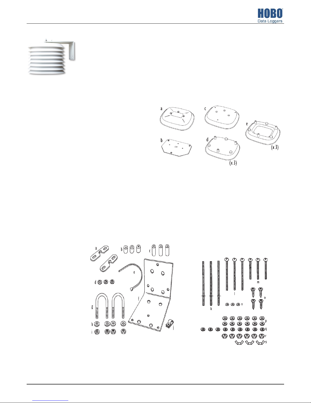
Components
There are two types of components to the Solar Radiation Shield: the plates that join together to form the
radiation shield and the installation hardware kit.
Radiation Shield Parts
a. One Cover Plate
b. One Support Plate
c. One Flat Plate
d. Three Closed Plates
e. Three Open Plates
Installation Hardware Kit
a. Two Clip Mounts
b. Three 1/2 in. (13 mm) spacers
c. Three 1 in. (25 mm) spacers
d. Three Plastic Screw Retainers
e. One Cable Tie
f. One Wall Mount Bracket
g. Two 1-1/2 in. U-bolts
h. Four 1/4 in. Flat Washers
i. Four 1/4 in. Hex Nuts
j. One Cable Clamp
k. Three # 8 x 5 in. (127 mm long) Threaded Rods
with #8 Push Nuts
l. Three #8 x 2-3/4 in. (70 mm long) Pan Head
Screws
m. Three #8 x 1-3/4 in. (44 mm long) Pan Head
Screws
n. Three #4 Flat Washers
o. Four #4 x 1/2 in. (13 mm long) Pan Head Self-
Threading Screws
p. Twelve #8 Flat Washers
q. Nine #8 Split Lock Washers
r. Six #8 Hex Nuts
s. Three 38 Wing Nuts
4115-C MAN-RS1
Find Quality Products Online at: sales@GlobalTestSupply.com
www.GlobalTestSupply.com
Page 2
Tools and Materials Needed
You may need the following tools and materials depending on
the logger you are using and how you will be mounting the
Solar Radiation Shield. Read this manual before beginning the
installation to be sure you have everything you need. It is
recommended that assemble as much of the shield as you can
before going to the field.
• Small Phillips-head screwdriver and medium slotted-head
screwdriver
• Wrench or pliers
• Drill with 3/16 in drill bit (4.7 mm) to drill pilot holes if
attaching Solar Radiation Shield to the top of a post
• Adjustable wrench or 11/32 in. wrench and 7/16 in.
wrench to tighten hex nuts (11/32 in wrench) or to drive
lag screws into wall or post (7/16 in wrench)
• Four 3/4 in x 1-1/2 in. lag screws (38 mm long) to attach
Solar Radiation Shield to a post or wall
• Three #8 x 1 in. screws (25 mm long) to attach Solar
Radiation Shield on the top of a post (if #8 x 2-3/4 in. pan
head screws provided create clearance problems)
• Tape to hold screws in place when assembling Solar
Radiation Shield
Solar Radiation Shield, Unassembled (RS1) Manual
Location Recommendations
Use the following guidelines to determine the best location for
mounting the Solar Radiation Shield.
• The Solar Radiation Shield works best when in a location
with a steady breeze. Mount away from fences, buildings,
trees, or other obstructions.
• Install over plants or soil if possible.
• Do not install over or near sprinklers. The Solar Radiation
Shield is not designed to protect the sensor from water
sprayed upwards.
• If attaching to a building, the preferred location is the
north side in the northern hemisphere and the south side
in the southern hemisphere.
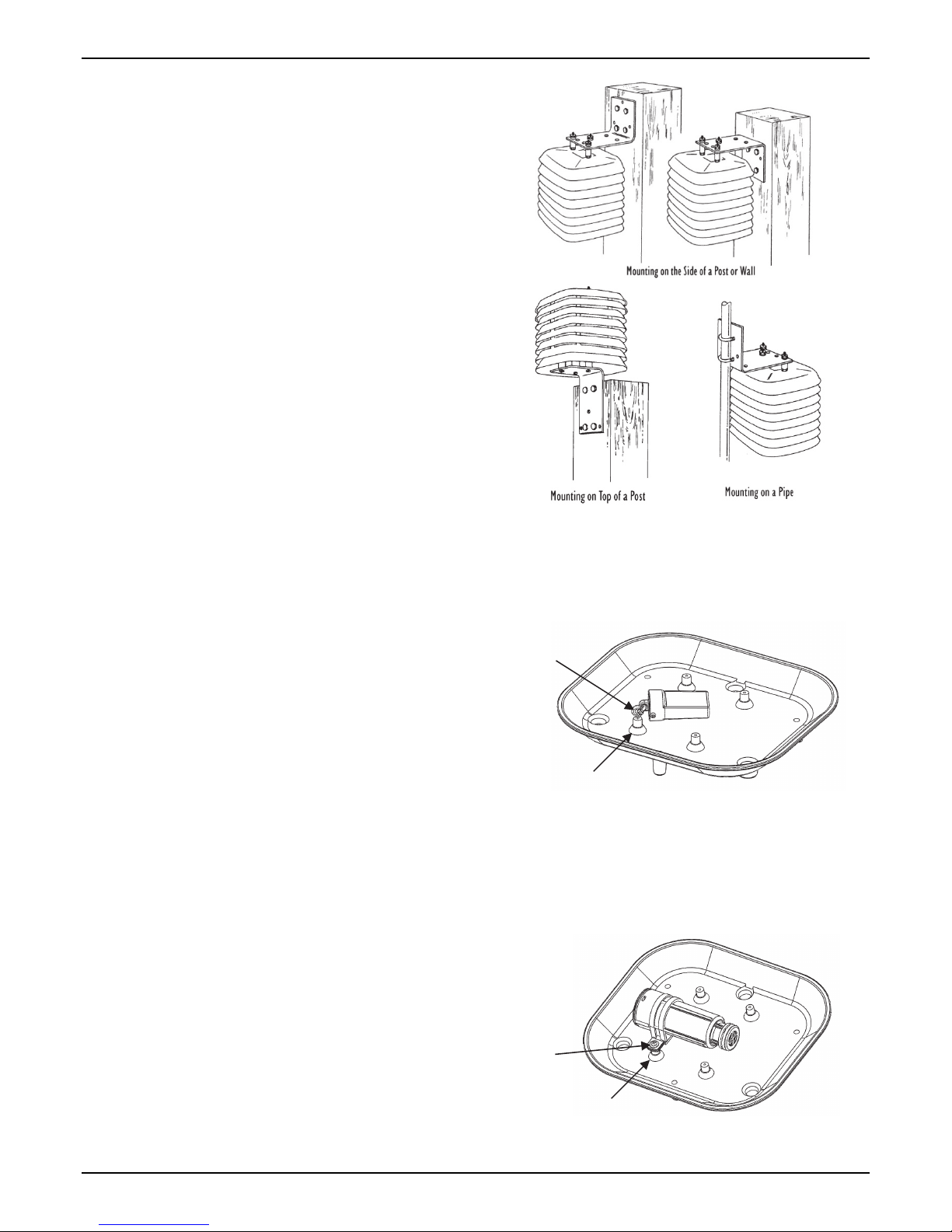
Mounting Options
The Solar Radiation Shield may be mounted in three
orientations.
• On the side of a wooden post or a wall
• On a metal pipe with outside diameter between 1 in. and
1-1/4 in. (25 mm and 31 mm)
• On top of a wood post
Determine which orientation best suits your needs before you
begin because the installation instructions differ slightly
depending on how you plan to mount the Solar Radiation
Shield. Note that if you are mounting to the side of a post or
wall, you will be attaching the mounting bracket to the top of
the shield (top mounting). If you are mounting to top of a post,
you will be attaching the bracket to the bottom of the shield
(bottom mounting).
Attaching HOBO Loggers
To attach a HOBO Pendant logger (UA-00x-xx) or a TidbiT v2
(UTBI-001) to the Solar Radiation Shield, install the 1/2 in.
screw eye provided with the RS1 into the standoff of the closed
plate as shown. Attach the logger with a tie wrap.
Screw eye
Standoff
To attach a HOBO Water Temp Pro v2 (U22-001) or a HOBO Pro
v2 Internal Temp/RH logger (U23-00x) to the Solar Radiation
Shield, place the logger in the clamp provided in the U23 Clamp
Kit. Secure the clamp into the standoff on the closed plate as
shown with the screw and washer provided in the kit. Note: The
HOBO Water Temp Pro v2 can be mounted into the shield using
the U23 Clamp Kit, but the clamp fit will not be as snug as it is for
the HOBO Pro v2 Internal Temp/RH logger.
Clamp
Standoff
1-800-LOGGERS 2 www.onsetcomp.com
Find Quality Products Online at: sales@GlobalTestSupply.com
www.GlobalTestSupply.com
Page 3
Solar Radiation Shield, Unassembled (RS1) Manual
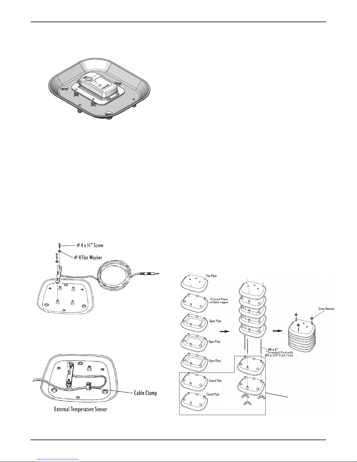
If using a HOBO MX2301 or MX2305 series logger with the Solar
Radiation Shield, attach the logger and bracket (MX2300-RSBRACKET) to the underside of the closed plate with the screws
included with the bracket as shown below.
Attaching an External Temperature Sensor
from a HOBO Logger
1. Place the sensor cable into the notch on one of the clip
mounts and hold it in place. Hold the clip mount so the
raised semi-circle at the top of the notch will face up.
2. Position the second clip mount over the first, with the notch
facing in the opposite direction, securing the sensor cable
between the two notches. When positioning the second clip
mount, make sure the raised semi-circle will face down.
3. Position the clip mounts over two of the mounting posts on
the closed plate. Make sure you orient the clip mounts as
shown at right.
4. Attach the clip mounts to the mounting posts using two of
the #4 x 1/2 in. pan head self-threading screws and two of
the #4 flat washers.
and a #4 flat washer) so that a loop of cable is formed.
Make sure to mount the clamp so that the flat side will be
up and the bulge side down. Tighten the screw completely
so that the cable cannot move within the cable clamp.
Assembling the Solar Radiation Shield to
Attach to the Side of a Post, Wall, or Pipe
The following instructions explain how to assemble the
mounting bracket to the top of the Solar Radiation Shield for
installation on the side of a post, a wall, or on a pipe. If you plan
to mount the Solar Radiation Shield on top of a post, follow the
instructions in Assembling the Solar Radiation Shield to Attach
to the Top of a Post on page 5.
Assembling the Solar Radiation Shield Plates
1. Slide each of the three #8 x 5 in. threaded rods, with push
nuts installed, through each of the three holes in the three
open plates. When inserting the threaded rods, make sure
the long end (when measured from the push nut) goes
through the holes in the open plates.
2. If you are using an external temperature sensor, feed the
entire remaining length of external temperature sensor
cable attached to the closed plate through the open centers
of the three open plates.
3. Slide the closed plate with the logger over the threaded rod
ends protruding from the top of the open plates so that
logger is enclosed within the center of the open plates.
4. Slide the flat plate over the threaded rod ends protruding
from the closed plate with the logger.
5. Place plastic screw retainers over the protruding threaded
rod ends.
6. Rest the partially assembled Solar Radiation Shield on a flat
surface and go to the next section.
5. Once secured, adjust the sensor so that it and
approximately 1/4 in. (6 mm) of cable protrude from the
clip mounts.
6. Place the cable clamp around the sensor cable
approximately 8 in. (20 cm) from the sensor.
Attached during
final assembly
7. Secure the cable clamp to one of the remaining mounting
posts (using a #4 x 1/2 in. pan head self-threading screw
1-800-LOGGERS 3 www.onsetcomp.com
Find Quality Products Online at: sales@GlobalTestSupply.com
www.GlobalTestSupply.com
Assembling the Radiation Shield Plates
Page 4

Solar Radiation Shield, Unassembled (RS1) Manual
Attaching the Support Plate to the Cover Plate
1. Slide the three #8 x 2-3/4 in. pan head screws up through
the non-threaded holes in the shield support plate. Make
sure the side of the support plate marked “UP” is in fact on
top as you slide the screws in from the bottom.
2. Place the cover plate over the screw ends protruding from
the support plate.
3. Place a 1-inch spacer over each of the screw ends.
4. Secure the support plate and spacers to the cover plate
using a #8 flat washer, #8 split lock washer, and #8 hex nut
on each of the screw ends. Tighten until the support plate is
firmly attached to the cover plate and then go to the next
section.
Attaching Support Plate to Cover Plate
Attaching the Cover Plate Assembly to the Solar
Radiation Shield
1. Place the cover plate assembly onto the stack of plates,
lining up the threaded rod ends with the threaded holes in
the bottom of the support plate.
2. With your finger, screw the three #8 x 5 in. threaded rods
into the support plate until tight. Go to the next section.
Completing the Final Assembly
1. Slide the lower closed plates over the threaded rods
protruding from the bottom of the partially assembled Solar
Radiation Shield. If you are using an external temperature
sensor, make sure the sensor cable is pulled completely
through the space between the lower open plate and the
adjacent closed plate during this final assembly.
2. Screw the #8 wing nuts on the threaded rods protruding
from the bottom of the assembled Solar Radiation Shield
until they are snug. Do not over tighten the wing nuts so
they can be easily removed for quick access to the logger
for reading out with a HOBO Shuttle.
Mounting on the Side of a Post or Wall
1. Using four 1/4 in. x 1-1/2 in. lag screws, attach the
mounting bracket to the mounting surface in the desired
location.
Attaching the Mounting Bracket to the Side of a Post
2. Slide the screw ends protruding from the top of the Solar
Radiation Shield assembly into the holes on the mounting
bracket.
3. Secure the mounting bracket to the Solar Radiation Shield
using a #8 flat washer, #8 split lock washer and #8 hex nut
on each of the screw ends. Tighten until the mounting
bracket is firmly attached to the Solar Radiation Shield.
Attaching Solar Radiation Shield to Mounting Bracket
Mounting to a Pipe
These instructions are for mounting to a pipe with an outside
diameter between 1 and 1-1/4 inches (25 and 31 mm).
Attaching the Cover Plate Assembly to Solar Radiation Shield
1-800-LOGGERS 4 www.onsetcomp.com
Find Quality Products Online at: sales@GlobalTestSupply.com
www.GlobalTestSupply.com
1. Slide the screw ends protruding from the top of the Solar
Radiation Shield assembly into the holes on the mounting
bracket.
Page 5

Solar Radiation Shield, Unassembled (RS1) Manual
2. Secure the mounting bracket to the Solar Radiation Shield
using a #8 flat washer, #8 split lock washer, and #8 hex nut
on each of the screw ends. Tighten until the mounting
bracket is firmly attached to the Solar Radiation Shield.
Attaching Solar Radiation Shield to Mounting Bracket
Attaching Mounting Bracket to a Pipe
3. Hold the mounting bracket against the pipe and slide the
ends of the two 1-1/2 in. U-bolts through the holes in the
back of the mounting bracket so that the U-bolts wrap
around the pipe.
4. Secure the mounting bracket to the pipe using a 1/4 in. flat
washer and a 1/4 in. hex nut on each end of the 1-1/2 in. Ubolts. Tighten until the mounting bracket is firmly attached
to the pipe.
Attaching Mounting Bracket
1. Using a drill with a 3/16 in. (4.7 mm) drill bit, drill three
holes through one of the closed plates in the locations
marked by the small dimples on the bottom of the plate. Do
not use the closed plate to which you attached the logger or
sensor.
Drilling Holes in Closed Plate
2. Place a #8 flat washer over the end of each of the #8 x 2-3/4
in. pan head screws. If the extra length of the screw end
protruding from the bottom of the Solar Radiation Shield
creates a clearance problem, you will need to use #8 x 1 in.
screws (not included).
3. Slide the three #8 x 2-3/4 in. pan head screws (with
washers) up through the holes you just drilled.
4. Place a small piece of tape over each of the screw heads to
keep the screws in place as you continue.
5. Place a 1/2 in. spacer over each of the screw ends
protruding from the closed plate.
6. Slide the mounting bracket over the screw ends protruding
from the closed plate.
7. Secure the mounting bracket to the closed plate using a #8
flat washer, a #8 split lock washer, and a #8 hex nut on each
of the screw ends. Tighten until the mounting bracket is
firmly attached to the closed plate and then go to the next
section.
Assembling the Solar Radiation Shield to
Attach to the Top of a Post
The following instructions explain how to assemble the
mounting bracket to the bottom of the Solar Radiation Shield
for installation on the top of a post. If you plan to mount the
Solar Radiation Shield to the side of a post, a wall, or on a pipe,
follow the instructions in Assembling the Solar Radiation Shield
to Attach to the Side of a Post, Wall, or Pipe on page 3.
1-800-LOGGERS 5 www.onsetcomp.com
Find Quality Products Online at: sales@GlobalTestSupply.com
www.GlobalTestSupply.com
Attaching Mounting Bracket
Page 6

Solar Radiation Shield, Unassembled (RS1) Manual
Assembling the Solar Radiation Shield Plates
1. Slide each of the three #8 x 5 in. threaded rods, with push
nuts installed, through each of the three holes in the three
open plates. When inserting the threaded rods, make sure
the long end (when measured from the push nut) goes
through the holes in the open plates.
2. If you are using an external temperature sensor, feed the
entire remaining length of external temperature sensor
cable attached to the closed plate through the open centers
of the three open plates.
3. Slide the closed plate with the logger over the threaded rod
ends protruding from the top of the open plates so that
logger is enclosed within the center of the open plates.
4. Slide the flat plate over the threaded rod ends protruding
from the closed plate with the logger.
5. Place plastic screw retainers over the protruding threaded
rod ends.
6. Rest the partially assembled Solar Radiation Shield on a flat
surface and go to the next section.
on each of the screw ends. Tighten until the support plate is
firmly attached to the cover plate and then go to the next
section.
Attaching Support Plate to Cover Plate
Attaching the Cover Plate Assembly to the Solar
Radiation Shield
1. Place the cover plate assembly onto the stack of plates,
lining up the threaded rod ends with the threaded holes in
the bottom of the support plate.
2. With your finger, screw the three #8 x 5 in. threaded rods
into the support plate until tight. Go to the next section.
Attached during
final assembly
Assembling the Radiation Shield Plates
Attaching the Support Plate to the Cover Plate for
Top Mounting
1. Slide the three #8 x 2-3/4 in. pan head screws up through
the non-threaded holes in the shield support plate. Make
sure the side of the support plate marked “UP” is in fact on
top as you slide the screws in from the bottom.
2. Place the cover plate over the screw ends protruding from
the support plate.
3. Secure the support plate and spacers to the cover plate
using a #8 flat washer, #8 split lock washer, and #8 hex nut
1-800-LOGGERS 6 www.onsetcomp.com
Attaching the Cover Plate Assembly to Solar Radiation Shield
Completing the Final Assembly
1. Slip the exposed ends of the #8 x 5 in. threaded rods
through the holes in the open plate and then the closed
plate with mounting brackets.
2. Screw the #8 wing nuts onto the exposed ends of the #8 x 5
in. threaded rods and tighten until snug. Go to the next
section.
Find Quality Products Online at: sales@GlobalTestSupply.com
www.GlobalTestSupply.com
Page 7

Solar Radiation Shield, Unassembled (RS1) Manual
Mounting to the Top of a Post
1. The mounting bracket should have already been installed
on the shield.
2. Use four 1/4 x 1-1/2 in. lag screws (not included) to attach
the mounting bracket to the mounting surface in the
desired location.
Attaching Mounting Bracket to the Top of a Post
Reading Out the Logger
To read out HOBO MX2300 loggers that do not have power
saving mode enabled, stand within communication range of the
shield and logger with a mobile device and use HOBOmobile®
to connect to the logger and read it out.
For MX2300 loggers with power saving mode enabled and all
other loggers, follow these steps to read out the data from the
logger:
1. Remove the bottom plates for a top-mounted shield, or
remove the top plates for a bottom-mounted shield.
2. If you are reading out a HOBO Pendant logger (UA-00x-xx)
or a TidbiT v2 (UTBI-001), you can keep the logger attached
to the shield while offloading data.
If you are reading out a MX2300 logger with power saving
mode enabled, keep the logger attached to the shield. Press
the button on the logger to wake up communications. Use
HOBOmobile to connect to the logger and read it out.
If you are reading out a HOBO Water Temp Pro v2 (U22-
001) or a HOBO Prov2 Internal Temp/RH logger (U23-00x),
unscrew the clamp that secures the logger to the shield and
remove the logger. After reading out the logger, place it
back in the clamp and screw it back in.
3. Reattach the bottom or top plates as applicable.
Maintenance Instructions
• The effectiveness of the Solar Radiation Shield will be
reduced if the surfaces of the shield become dirty. Wipe
the surfaces of the shield using a damp cloth to remove
dirt, debris, etc.
• Keep areas between Solar Radiation Shield plates free
of debris that may obstruct air flow e.g., leaves, twigs,
webs, nests. DO NOT remove nesting insects or animals
by spraying insect killer of any kind into the Solar
Radiation Shield because this may damage the sensors
and the Solar Radiation Shield.
© 2011–2016 Onset Computer Corporation. All rights reserved. Onset, HOBO, Pendant, and HOBOmobile are
registered trademarks of Onset Computer Corporation. All other trademarks are the property of their
respective companies.
4115-C MAN-RS1
Find Quality Products Online at: sales@GlobalTestSupply.com
www.GlobalTestSupply.com
 Loading...