

Page 1
HOBO® MX Water Level Logger (MX2001-0x) Manual
Pressure
Operation Range
Factory Calibrated Range
Burst
Water Level Accuracy*
Raw Pressure Accuracy**
Resolution
Pressure Response Time (90%)
Pressure
Operation Range
0 to 400 kPa (0 to 58 psia); approximately 0 to 30.6 m (0 to 100 ft)
of water depth at sea level, or 0 to 33.6 m (0 to 111 ft) of water at
Factory Calibrated Range
Burst
Water Level Accuracy*
Typical error: ±0.05% FS, 1.5 cm (0.05 ft) water
Maximum error: ±0.1% FS, 3.0 cm (0.1 ft) water
Raw Pressure Accuracy**
Resolution
Pressure Response Time (90%)
Pressure (Absolute) and Water Level Measurements
Operation Range
Factory Calibrated Range
Burst Pressure
Water Level Accuracy*
Raw Pressure Accuracy**
Resolution
Pressure Response Time (90%)***
HOBO MX Water Level
Logger
Models:
• MX2001-01 or MX2001-01-Ti
(Titanium), 9-meter/30-foot
depth)
• MX2001-02, 30-meter/100-foot
depth
• MX2001-03, 76-meter/250-foot
depth
• MX2001-04 or MX2001-04-Ti
(Titanium), 4-meter/13-foot
depth
Note: Each model consists of a
sensor end (MX2001-0x-S or
MX2001-0x-Ti-S) and a top end
(MX2001-TOP).
Included Items:
• Two AA 1.5 V Batteries
• Logger consisting of a top end
and sensor end connected by a
cable in desired length (ordered
separately)
Required Items:
• HOBOconnect app
• Mobile device with Bluetooth
and iOS, iPadOS®, or Android™
• Cable (CABLE-DR-xxx)
Accessory:
• Well cap (WELL-CAP-01)
The HOBO MX water level logger is used for monitoring changing water levels in a wide
range of applications, including streams, lakes, wetlands, tidal areas, and groundwater.
This Bluetooth® Low Energy-enabled logger is designed for wireless communication
with a mobile device. Using the HOBOconnect™ app, you can easily configure the logger
and read it out—all from its deployed location—to your phone or tablet where you can
view the logged data or share it for further analysis. With the app, you can also set a
reference water level and water density, configure up to 8 logging intervals, log
statistics, configure an alarm to trip at thresholds you specify, or set up burst logging in
which data is logged at a different interval when sensor readings are above or below
certain limits. This logger features a ceramic pressure sensor, durable housing, and an
integrated barometric pressure sensor for barometric compensation in the logger,
which allows for direct water level readout without needing to do any post processing.
An optional cap is also available for deployment in existing wells or stilling wells.
Without cumbersome vent tubes or desiccants to maintain and convenient data
retrieval to a phone or tablet, this easy-to-use logger is an ideal solution for water level
studies and research.
Specifications
(Absolute) and Water Level Measurements MX2001-01-S and MX2001-01-Ti-S
0 to 207 kPa (0 to 30 psia); approximately 0 to 9 m (0 to 30 ft) of
69 to 207 kPa (10 to 30 psia), 0° to 40°C (32° to 104°F)
Pressure 310 kPa (45 psia) or 18 m (60 ft) depth
Typical error: ±0.05% FS, 0.5 cm (0.015 ft) water
±0.3% FS, 0.62 kPa (0.09 psi) maximum error
<0.02 kPa (0.003 psi), 0.21 cm (0.007 ft) water
(Absolute) and Water Level Measurements MX2001-02-S
69 to 400 kPa (10 to 58 psia), 0° to 40°C (32° to 104°F)
Pressure 500 kPa (72.5 psia) or 40.8 m (134 ft) depth
±0.3% FS, 1.20 kPa (0.17 psi) maximum error
<0.04 kPa (0.006 psi), 0.41 cm (0.013 ft) water
0 to 850 kPa (0 to 123.3 psia); approximately 0 to 76.5 m (0 to
69 to 850 kPa (10 to 123.3 psia), 0° to 40°C (32° to 104°F)
1,200 kPa (174 psia) or 112 m (368 ft) depth
±0.3% FS, 2.55 kPa (0.37 psi) maximum error
<0.085 kPa (0.012 psi), 0.87 cm (0.028 ft) water
water depth at sea level, or 0 to 12 m (0 to 40 ft) of water at
3,000 m (10,000 ft) of altitude
Maximum error: ±0.1% FS, 1.0 cm (0.03 ft) water
*** <1 second at a stable temperature
3,000 m (10,000 ft) of altitude
*** <1 second at a stable temperature
MX2001-03-S
251 ft) of water depth at sea level, or 0 to 79.5 m (0 to 262 ft)
of water at 3,000 m (10,000 ft) of altitude
Typical error: ±0.05% FS, 3.8 cm (0.125 ft) water
Maximum error: ±0.1% FS, 7.6 cm (0.25 ft) water
<1 second at a stable temperature
19389-N
Page 2
Specifications (continued)
Pressure
Operation Range
Factory Calibrated Range
Burst Pressure
Water Level Accuracy*
Raw Pressure Accuracy**
Resolution
Pressure Response Time (90%)
Barometric Pressure (
Operation Range
Temperature Calibrated Range
Accuracy
Water Level Accuracy*
Resolution
Response Time
Stability (Drift)
Temperature Measurements (All
Operation Range
Accuracy
Resolution
Response Time (90%)
Stability (Drift)
Logger
Operating Range
Radio Power
Transmission Range
Wireless Data Standard
Logging Rate
Logging Modes
Memory Modes
Start Modes
Stop Modes
Time
Battery
Battery Life
Memory
Full Memory Download Time
Approximately 2 minutes; may take longer the further the device is from the top end of the logger
Dimensions
(Absolute) and Water Level Measurements MX2001-04-S and MX2001-04-Ti-S
0 to 145 kPa (0 to 21 psia); approximately 0 to 4 m (0 to 13 ft) of water depth at sea level, or 0 to 7 m (0 to 23 ft)
69 to 145 kPa (10 to 21 psia), 0° to 40°C (32° to 104°F)
310 kPa (45 psia) or 18 m (60 ft) depth
Typical error: ±0.075% FS, 0.3 cm (0.01 ft) water
±0.3% FS, 0.43 kPa (0.063 psi) maximum error
<0.014 kPa (0.002 psi), 0.14 cm (0.005 ft) water
*** <1 second at a stable temperature
MX2001-TOP)
66 to 107 kPa (9.57 to 15.52 psia)
-20 to 50°C (-4 to 122°C)
±0.2 kPa (±0.029 psi) over full temperature range at fixed pressure; maximum error ±0.5% FS
Typical error: ±0.075% FS, 0.3 cm (0.01 ft) water
<0.01 kPa (0.0015 psi)
<1 second at stable temperature
<0.01 kPa (0.0015 psi) per year
HOBO MX Water Level Logger (MX2001-0x) Manual
of water at 3,000 m (10,000 ft) of altitude
Maximum error: ±0.15% FS, 0.6 cm (0.02 ft) water
Maximum error: ±0.15% FS, 0.6 cm (0.02 ft) water
Sensor End Models MX2001-0x-S and MX2001-0x-Ti-S)
-20° to 50°C (-4° to 122°F)
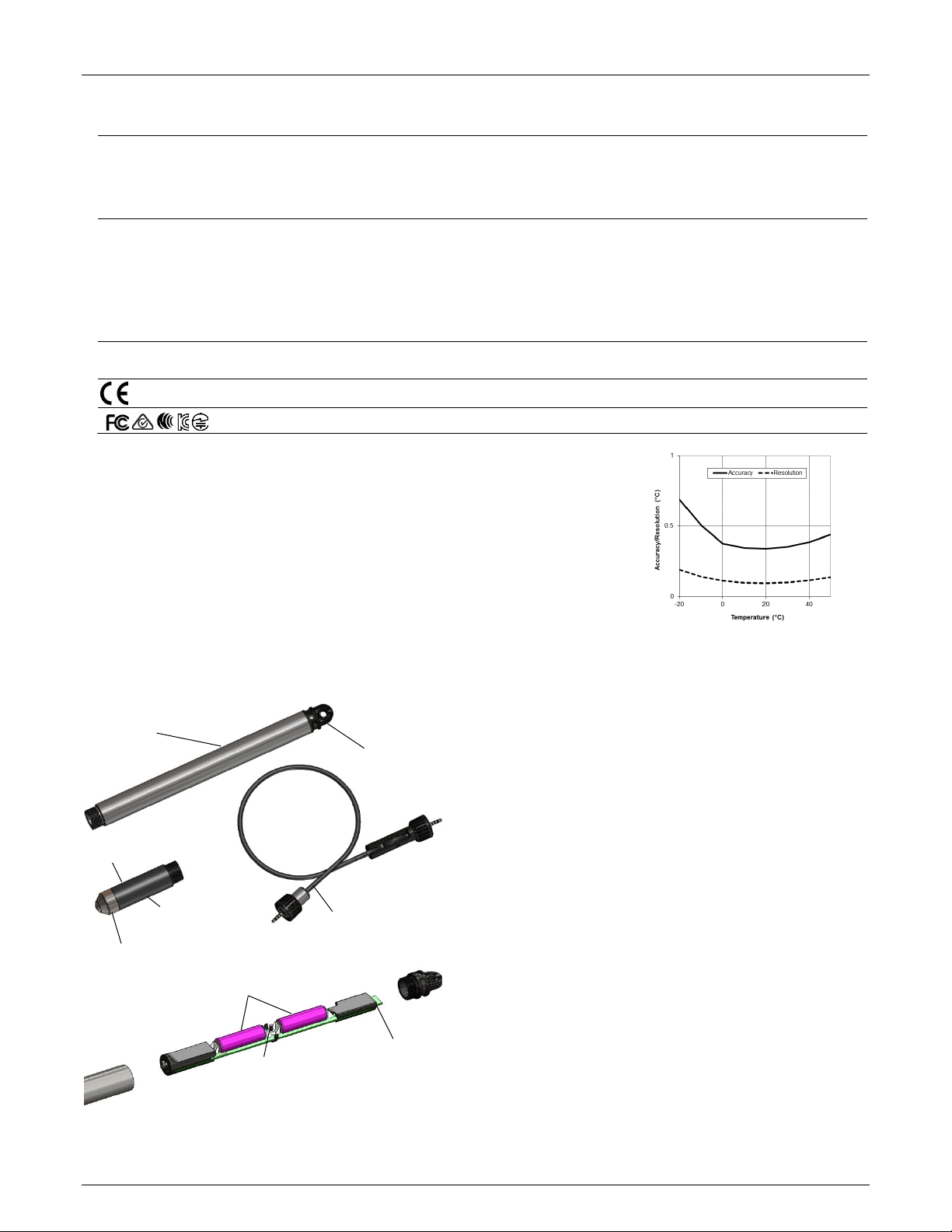
±0.44°C from 0° to 50°C (±0.79°F from 32° to 122°F), see Plot A
0.1°C at 25°C (0.18°F at 77°F), see Plot A
5 minutes in water (typical)
0.1°C (0.18°F) per year
-20° to 50°C (-4° to 122°F)
1 mW (0 dBm)
Approximately 30.5 m (100 ft) line-of-sight
Bluetooth Low Energy (Bluetooth Smart®)
1 second to 18 hours
Fixed interval, multiple intervals with up to 8 user-defined logging intervals and durations, or burst
Wrap when full or stop when full
Immediate, date & time, or next interval
When memory full, date & time, or after a set logging period
Accuracy ±1 minute per month 0° to 50°C (32° to 122°F)
Two AA, 1.5 V alkaline batteries, user replaceable
1 year, typical with logging interval of 1 minute. Faster logging and/or statistics sampling intervals, entering
256 KB memory (30,000 sets of measurements)
Top end (MX2001-TOP): 2.54 cm (1.0 inches) diameter, 28.9 cm (11.4 inches) length; mounting hole 7.6 mm
burst logging mode, excessive readouts, checking of Full Status Details, and remaining connected with the app
will impact battery life.
(0.3 inches) diameter
Sensor end (MX2001-0x-S and MX2001-0x-Ti-S: 2.54 cm (1.0 inches) diameter, 9.91 cm (3.9 inches) length
Note: The length of the water level logger cable (CABLE-DR-xxx) can vary -0% to +3% +10 cm (3.9 inches) from
the length ordered. The logger adds 38.8 cm (15.3) inches to the length of the cable ordered.
1-800-LOGGERS 2 www.onsetcomp.com
Page 3
Specifications (continued)
Weight
Wetted Materials
Environmental Rating
End cap with
Top end
Sensor end
Water level logger cable
Pressure sensors (inside)
Temperature
sensor (inside)
Password reset
button
LED (Not Visible)
Battery holders
Plot A
HOBO MX Water Level Logger (MX2001-0x) Manual
Top end (MX2001-TOP): PVC housing, Polycarbonate end cap, Viton O-ring
Top end: NEMA 6, IP67
* Water Level Accuracy: With accurate reference water level measurement, known water density,
and a stable temperature environment. System Water Level Accuracy equals the sum of the
Barometric Water Level Accuracy plus the selected sensor end Water Level Accuracy.
** Raw Pressure Accuracy: Absolute pressure sensor accuracy includes all sensor drift, temperature,
and hysteresis-induced errors.
*** Changes in Temperature: Allow 20 minutes in water to achieve full temperature compensation of
the pressure sensor. There can be up to 0.5% of additional error due to rapid temperature
changes. Measurement accuracy also depends on temperature response time.
Logger Components and Operation
Top end (MX2001-TOP): Approximately 136 g (4.78 oz) in air
Stainless sensor end (MX2001-0x-S): Approximately 106 g (3.74 oz) in air; approximately 53.9 g (1.9 oz) in fresh
water
Titanium sensor end (MX2001-0x-Ti-S): Approximately 80 g (2.83 oz) in air; approximately 37 g (1.3 oz) in fresh
water
Stainless sensor end (MX2001-0x-S): Acetal housing, Viton and Buna-N O-rings, ceramic sensor in stainless steel
end cap
Titanium sensor end (MX2001-0x-Ti-S): Acetal housing, Viton and Buna-N O-rings, ceramic sensor in Titanium
end cap
Cable (CABLE-DR-XXX): Polycarbonate end cap, PVC end cap, nylon collar nut, Viton O-rings, polyurethane
jacket
Sensor end: IP68
The CE Marking identifies this product as complying with all relevant directives in the European Union (EU).
See last page
The MX water level logger consists of a top end and a sensor
end that is connected by a water level logger cable. The three
components work together to allow for wireless transfer of
data to the app on a mobile phone or tablet. This is an overview
of each main component and the internal components in the
mounting hole
top end:
• Top end. This contains the Bluetooth wireless
communication and two AA batteries. This top end unit is
suspended from the top of the well using the mounting
hole in the end cap (see Deploying the Logger).
• Sensor end. This measures the pressure and temperature
in the water. The nose cone on the sensor end houses the
pressure sensors and the body of the sensor end houses
the temperature sensor.
• Water level logger cable. This is the cable that connects
the top end to the sensor end. Data measured by the
sensor is transmitted through the cable to the top end
where it is logged for later upload to a mobile phone or
tablet (see Configuring the Logger).
• Battery holders. Two AA batteries are installed in the
battery holders in the top end (see Battery Information).
• Password reset button. Press the button between the two
batteries in the top end to reset the logger password to
the factory default (see Setting a Logger Password).
Disassembled top end
• LED. Remove the end cap from the top end to view the
red LED below the top edge of the circuit board. This LED
blinks every second while logging and every 8 seconds
1-800-LOGGERS 3 www.onsetcomp.com
Page 4
HOBO MX Water Level Logger (MX2001-0x) Manual
Logger
Plug this portion of the cable
Plug this portion of the cable with the
when the logger is configured to start on a specific
date/time or on the next logging interval. The LED will also
blink once when you press the password reset button and
blink quickly multiple times when the batteries are
installed.
When the three components are deployed together, you can then configure the logger or offload data to your mobile device without having to pull the logger up to the surface.
Factory Calibration
The pressure sensors in the sensor end are individually
calibrated. During calibration, raw pressure sensor data is
collected at multiple pressures and temperatures over the
calibrated range of the logger (see Specifications). This data is
used to generate calibration coefficients that are stored in the
sensor end’s non-volatile memory. The calibration coefficients
are then checked to be sure that the logger meets its stated
accuracy over the calibrated range. The pressure sensor can be
used at pressures and temperatures that are outside of the
calibrated range, but the accuracy cannot be guaranteed.
Important: Never exceed the burst pressure of the sensor!
Configuring the Logger
Follow these steps to begin using the logger. After completing
steps 1–4, it is recommended that you perform a trial run of
steps 5 through 12 before deploying the logger.
Important: When assembling the logger or attaching the cable,
make sure the O-rings and mating housing surfaces are clear of
any debris. Any contamination of these surfaces can cause leaks
that will lead to logger failure.
1. Install the batteries in the top end. See Battery Information
for details.
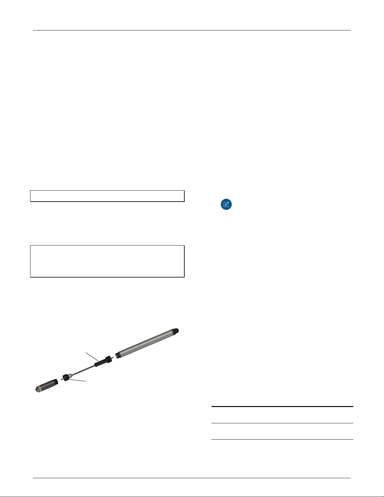
2. Connect the logger components. Connect the top end to
the sensor end with the water level logger cable as shown
below. The end of the cable with the longer housing
connects to the top end as shown below.
with the longer housing into
the top end and screw to
tighten (hand tight)
smaller housing into the sensor end and
screw to tighten (hand tight)
3. Download the app. Go to the App Store® or Google Play™
and download HOBOconnect to your phone or tablet.
4. Open the app. Enable Bluetooth in your device settings if
prompted.
5. Determine the logger is within range. Tap Devices. The
logger should appear in the list of devices (note that the
serial number shown in the app is for the top end of the
logger). If the logger does not appear, make sure it is within
range of your device. Note that sensor readings are
displayed as “--“ when the logger is stopped.
6. Deploy the logger if ready. If you are ready to deploy the
logger, place it in the deployment location (see Deploying
the Logger for deployment guidelines). Otherwise, skip
deployment and complete the following steps as a test.
7. Connect to the logger. Tap the logger in the app to connect
to it. Tips for connecting:
• Make sure the top end of the logger is within range of
your mobile device. The range for successful wireless
communication is approximately 30.5 m (100 ft) with full
line-of-sight.
• If your device can connect to the logger intermittently or
loses its connection, move closer to the top end of the
logger, within sight if possible.
• If the logger appears in the app, but you cannot connect
to it or if you are experiencing persistent connection
problems, close the app and power cycle the mobile
device (turn it off, wait a minute, and turn it back on).
This forces the previous Bluetooth connection to close.
8. Configure the logger. Once connected to the logger,
tap to set up the logger.
9. Set the Reference Water Level and Water Density.
a. Under Deployment Information, tap Reference Water
Level and enter the current water level as the reference
level in meters or feet. Water levels that are below the
reference point should be entered as negative values.
The reference water level entered will be associated with
the first data point once logging begins to determine the
correction factor to be used for water level data.
b. Tap water density and select one from the list for the
deployment or enter your own value under Manual
Input.
c. Tap Save to return to the Configuration screen.
10. Enable the desired sensors. Scroll down in the
Configuration screen to select the measurement
parameters to be logged. Differential pressure must be
enabled to calculate water level. Temperature must be
enabled to log absolute pressure. Temperature must also
be enabled if you selected the water density option “Fresh
Water adjusted for Temp” because the temperature values
are used to calculate the water density.
11. Finish configuring the logger. Select any of the following
logger settings as desired. The following table provides an
overview of the settings. For complete details, see the app
user’s guide at www.onsetcomp.com/hoboconnect.
Setting Action
Name
Group Tap Group to add the logger to a group (optional).
Enter a name for the logger (optional). If no name
is entered, the logger serial number is used.
Tap Save.
1-800-LOGGERS 4 www.onsetcomp.com
Page 5

HOBO MX Water Level Logger (MX2001-0x) Manual
Logger
• Statistics. Select any statistics you want to
Logger
record (maximum, minimum, average, and
> > >
Setting Action
Logging
Intervals
Start
Logging
Options
Stop
Logging
Options
Logging
Mode and
Statistics
Tap Logging Intervals and select how often the
logger will record data. When selecting a logging
interval, keep in mind that data offload time is
proportional to the amount of data logged. The
faster the logging interval, the more data that will
need to be offloaded and the longer it will take.
Multi-Rate Logging
You can set a total of 8 logging intervals. After
tapping Logging Intervals and entering a rate for
Interval 1, tap Add to set up additional logging
intervals. For each interval, enter the rate and
select the number of samples that will be
recorded for the selected rate. Tap Save.
Tap Start Logging and choose one of the following:
• Now. Logging will begin immediately after the
configuration settings are saved to the logger.
• On Next Logging Interval. Logging will begin at
the next even interval as determined by the
selected logging interval.
• On Date/Time. Logging will begin at a date and
time you specify.
Tap Save.
Tap Stop Logging and choose a memory option:
• When Memory Fills. The logger will continue
recording data until the memory is full.
• Never (Wrap When Full). The logger will
continue recording data indefinitely, with
newest data overwriting the oldest. This option
is not available if the Logging Mode is set to
Burst (see Burst Logging) or if you set up
multiple logging intervals.
Select one of the following time options for when
to stop logging:
• Never. Select this if you do not want the logger
to stop at any predetermined time frame.
• On Date/Time. Select this if you want the logger
to stop logging on a specific date and time.
Select the date and time.
• After. Select this if you want to control how
long the logger should continue logging once it
starts. Choose the amount of time you want the
logger to log data. For example, select 30 days if
you want the logger to log data for 30 days after
logging begins.
Tap Save.
Tap Logging Mode. Choose the logging mode (note
that you cannot change the logging mode if you
have multiple logging intervals configured):
• Fixed Logging. Select Normal to record the
current reading for each enabled sensor at each
logging interval. Note that this is also the mode
you need to select for multi-rate logging. You
must select Normal if you want to log water
level and barometric pressure data. If you
deselect Normal, the logger will only record
statistics series for the enabled series. It will not
be able to calculate water level or barometric
pressure.
Setting Action
standard deviation) and set the statistics
sampling interval. Statistics are not available for
water level and barometric pressure data. See
Statistics Logging for more information.
• Burst Logging. Select this to enable burst mode
in which logging can occur at a faster rate when
a specified trigger level is exceeded. See Burst
Logging for more information.
•
Sensors &
Alarm
Setup
After enabling the sensors as described in step 10,
set up any alarms. See Setting up Alarms for
details.
12. Save the configuration settings. Tap to save the
configuration settings The logger will begin logging data
based on the settings you selected. After logging begins,
you can read out the logger at any time (see Reading Out
the Logger for details). You can update the reference water
level or water density during the deployment if necessary
(see Updating the Reference Water Level and Water
Density).
Notes:
• When the logger is stopped, the water level reading
shown while connected to the logger does not reflect any
reference water level and water density values you have
entered (it reverts to a reference water level of zero and
a water density of “Fresh Water adjusted for
Temperature”). Once logging begins, the readings shown
in the app will be based on the reference water level and
water density you entered.
• If the logger is logging and you start a new deployment,
the logger will take a current water level reading and use
that as the default reference reading for the new
deployment.
• These are the options available when the logger is
connected to the app:
Tap this: To do this:
Select logger settings and save them onto the
logger to start logging. See Configuring the
Logger.
Read out (offload) logger data. See Reading Out
the Logger.
Start or restart logging depending on the
configuration settings selected in Configuring the
Logger.
Set a password for the logger that will be
required if another mobile device attempts to
connect to it. To reset a password, press the
reset button between the batteries inside the
logger or tap and tap Reset.
Mark the logger as a favorite. You can then filter
the list of devices to only show loggers marked as
favorites.
1-800-LOGGERS 5 www.onsetcomp.com
Page 6

HOBO MX Water Level Logger (MX2001-0x) Manual
>
Make sure the
level
10.0 mm (0.39 in.)
Update the firmware on the logger. A logger
readout will be completed automatically at the
beginning of the firmware update process
Important: Before updating the firmware on
the logger, check the remaining battery level
and make sure it is no less than 30%. Make
sure you have the time to complete the
entire update process, which requires that
the logger remains connected to the device
during the upgrade.
Deploying the Logger
The logger is designed to be easy to deploy in many
environments. The logger includes an absolute pressure sensor
and a barometric pressure sensor so no vent tube is required.
Follow these guidelines when deploying the logger:
• The absolute pressure sensor is temperature
compensated over the range of 0° to 40°C (32° to 104°F).
The barometric pressure sensor is temperature
compensated over the range of -20° to 50°C (-4° to
122°F). To obtain the highest level of accuracy, both the
sensor end and top end units of the logger should be
allowed to come to full temperature equilibrium
(approximately 20 minutes) before the reference level is
entered.
• Sudden temperature changes should be avoided.
• When deploying the logger in a well, make sure the well
is vented to the atmosphere. Typically, a small hole can
be drilled in the side of the well cap to ensure that the
pressure inside and outside the well is at equilibrium.
You can also use the Onset well cap (WELL-CAP-01).
• The sensor face located in the nose cone of the sensor
end needs to be in the water to measure water level.
sensor face
(represented by
dashed lines in
this diagram) is in
the water to
measure water
• There is a vent for the barometric sensor at the top of
the logger (in the top end). This vent must not collect
water or it will block proper barometric pressure
readings. To avoid collecting water, the logger should be
hung vertically and the vent hole in the well cap should
not be oriented directly above the vent in the top end of
the logger. If the logger must be mounted at an angle,
the vent in the top end should point down so that any
water will drain out of it.
• Consider using slots for a mounting bolt at the top of the
well rather than holes so that the logger can be pulled up
easily for well access without having to remove nuts in
the field. This can reduce the chances for small parts
falling into the water and being lost.
• Any change in length of the logger cable will result in a 1-
to-1 corresponding error in the depth measurement.
Always pull-test a cable prior to deploying a logger in a
well to make sure it does not stretch.
• The top of the logger must be close to the surface and
not shielded in metal so that your phone or tablet can
connect to it. The maximum range for communication is
30.5 m (100 ft) with full line-of-sight.
• If you are deploying the logger in a lake, river, or stream,
you must first build a stilling well to protect the logger,
sensor, and cable. A simple stilling well can be constructed
with PVC or ABS pipe. A properly constructed stilling well
holds the sensor in position and protects the logger
components from currents, wave action, and debris.
Suspend the sensor end in the stilling well so it is always
underwater, but not on the bottom to be buried by silt.
For more information, see the Technical Application Note
for Constructing a Stilling Well at:
http://www.onsetcomp.com/water_level_stilling_well.html
• To prevent the sensor from moving in currents and to
ensure the support cable is kept straight during
deployment, you may need to add a weight to the
suspension cable just above the sensor or hang a weight
below the sensor. In some cases, you may need to both
add a weight and use a stilling well.
• Be very careful not to exceed the burst pressure for the
sensor. The pressure sensor will burst if the maximum
depth is exceeded (see Specifications). The sensor should
be positioned at a depth where it will remain in the water
duration of the deployment, but not exceed the
for the
rated bursting depth.
To deploy the logger:
1. Make sure the top end is connected to the sensor end with
the water level logger cable as described in Getting Started
with the Logger.
2. Attach any small parts, such as bolts with nuts, before you
go into the field so you don’t risk losing them in the field.
3. Lower the logger into the well or stilling well.
4. Use the Onset well cap if it is a 5 cm (2 inch) well.
Otherwise, use a 1/4-inch bolt of sufficient length to span
the well top or washer. Mount the logger as follows:
• The top end must be above any metal well to ensure
good wireless transmission.
1-800-LOGGERS 6 www.onsetcomp.com
Page 7

HOBO MX Water Level Logger (MX2001-0x) Manual
• Make sure there is access for measuring the water level
in the well. In some cases, such as when using the Onset
well cap, it will be necessary to pull the top end of the
logger out of the well to get a water level meter sensor
into the well.
• Make sure the logger cannot accidentally fall in the well.
• If the cable is too long, loop the cable and secure the
cable with multiple zip ties to ensure the loop does not
slip. The looped cable should be tight enough that the
cable can be easily pulled out of the well if necessary, but
it must not bend the cable any tighter than a 1.25 cm (0.5
inch) radius to prevent damage to the cable.
5. Measure the water level from the desired reference point
(top of pipe, ground level, or sea level) and enter it in the
app. Note that you may need to pull the top end out of the
well to gain access for measuring the water level within the
well. Follow these guidelines for determining the reference
level:
• To maximize accuracy, allow 20 minutes after deploying
the logger before measuring water depth to allow the
logger to reach temperature equilibrium with the water.
• If the well is too small in diameter to measure the water
depth while the logger is deployed, measure the water
depth before deployment, then deploy the logger
immediately.
• If the water level surface is below the reference point as
shown below, enter the reference water level in the app
as a negative number.
• If the water level surface is above the reference point as
shown below, enter the reference water level in the app
as a positive number.
• If you are using the sensor as the reference point as
shown below, enter the reference water level in the app
as zero and start the logger before the sensor is in the
water. The logged water level readings will represent the
height above the sensor.
Setting up Alarms
You can set an alarm to trip on the logger when a sensor
reading rises above or falls below a specified value. This can
alert you to problems so you can take corrective action. To set
an alarm:
1. Tap Devices. Tap the logger in the app to connect to it and
tap .
2. If you are going to set up a water level alarm, you must
enter the reference water level and water density before
setting the alarm levels.
3. Tap the Differential Pressure sensor if you want to set a
water level alarm. Tap the Temperature sensor to set a
temperature alarm. You cannot configure alarms for
absolute pressure. Note: The fixed logging mode must be
set to normal to configure a water level alarm.
4. Select High if you want an alarm to trip when the sensor
reading rises above the high alarm value. Drag the slider or
type a value to set the high alarm value. If you are
configuring a water level alarm, enter the limit value for
water level and app will show the differential pressure level
that will be used to trigger the alarm in the logger.
5. Select Low if you want an alarm to trip when the sensor
reading falls below the low alarm value. Drag the slider or
type a value to set the low alarm value.
6. For the Duration, select how much time should elapse
before the alarm trips and select one of the following:
7. Cumulative. The alarm will trip once the sensor reading is
out of the acceptable range for the selected duration any
time during logging. For example, if the high alarm is set to
85°F and the duration is set to 30 minutes, then the alarm
will trip once the sensor readings have been above 85°F for
a total of 30 minutes since the logger was configured.
8. Consecutive. The alarm will trip once the sensor reading is
out of the acceptable range continuously for the selected
duration. For example, the high alarm is set to 85°F and the
duration is set to 30 minutes, then the alarm will only trip if
1-800-LOGGERS 7 www.onsetcomp.com
Page 8

HOBO MX Water Level Logger (MX2001-0x) Manual
all sensor readings are 85°F or above for a continuous 30minute period.
9. Tap Save and repeat steps 3–8 for the other sensor if
desired.
10. Back in the Configuration settings, the Sensor in Limits
alarm option should be enabled. This indicates the alarm
icon will remain visible in the app until the sensor reading
returns to the normal range between any configured high
and low alarm limits.
11. Tap .
Notes:
• The actual values for the high and low alarm limits are set
to the closest value supported by the logger. In addition,
alarms can trip or clear when the sensor reading is within
the resolution specifications. This means the value that
triggers the alarm may differ slightly than the value
entered.
• When setting water level alarm limits, make sure that the
water level remains constant from the time alarm limits
are set until the time the logger is started.
• If you need to change the reference water level during
the deployment, you will also need to re-enter the alarm
limits based on the new reference water level.
• The alarm icon will appear in the app next to the logger
name or serial number when the alarm trips if the device
is within range of the logger.
• Once an alarm condition clears, the alarm icon in the app
will go away. There is no option to keep the alarm icon
visible until the logger is reconfigured.
• When you read out the logger, alarm events can be
displayed on the plot or in the data file. See Logger
Events.
Burst Logging
Burst logging is a logging mode that allows you to set up more
frequent logging when a specified condition is met. For
example, a logger is recording data at a 5-minute logging
interval and burst logging can be configured to log every 30
seconds when the water temperature rises above 85°F (the
high limit) or falls below 32°F (the low limit). This means the
logger will record data every 5 minutes as long as the water
temperature remains between 85°F and 32°F. Once the water
temperature rises above 85°F, the logger will switch to the
faster logging rate and record data every 30 seconds until the
temperature falls back to 85°F. At that time, logging then
resumes every 5 minutes at the normal logging interval.
Similarly, if the temperature falls below 32°F, then the logger
would switch to burst logging mode again and record data
every 30 seconds. Once the water temperature rises back to
32°F, the logger will then return to normal mode, logging every
5 minutes. Note: Sensor alarms, statistics, and the Stop Logging
option “Wrap When Full” are not available in burst logging
mode.
To set up burst logging:
1. Tap Devices. Tap the logger in the app to connect to it and
tap .
2. If you are going to set up burst logging for water level, you
must enter the reference water level and water density
before setting the burst limits.
3. Tap Logging Mode and then tap Burst Logging.
4. Select Low and/or High and either type or drag the slider to
set the low and/or high values. If you are configuring burst
logging for water level, enter the limit value for water level
and the app will show the differential pressure level that
will be used to trigger burst logging in the logger.
5. Repeat step 4 for the other sensor if desired.
6. Set the burst logging interval, which must be faster than the
logging interval. Keep in mind that the more frequent the
burst logging rate, the greater the impact on battery life
and the shorter the logging duration.
7. Tap Save.
8. Tap .
Notes:
• Once the logger is configured, the high and low burst
limits are checked once every 15 seconds. Therefore, if
you set the logging interval to less than 15 seconds and
the sensor reading falls outside the levels, the burst
logging will not begin until the next 15-second refresh
cycle.
• If high and/or low limits have been configured for more
than one sensor, then burst logging will begin when any
high or low condition goes out of range. Burst logging will
not end until all conditions on all sensors are back within
normal range.
• The actual values for the burst logging limits are set to
the closest value supported by the logger.
• When setting water level limits for burst logging mode,
make sure the water level remains constant from when
the burst limits are set until when the logger is started.
• If you need to change the reference water level during
the deployment, you will also need to re-enter the burst
limits based on the new reference water level.
• Burst logging mode can begin or end when the sensor
reading is within the resolution specifications. This means
the value that triggers burst logging may differ slightly
than the value entered.
• Once the high or low condition clears, the logging
interval time will be calculated using the last recorded
data point in burst logging mode, not the last data point
recorded in normal mode. For example, let’s assume the
logger has a 10-minute logging interval and logged a data
point at 9:05. Then, the high limit was surpassed and
burst logging began at 9:06. Burst logging then continued
until 9:12 when the sensor reading fell back below the
high limit. Now back in normal mode, the next logging
interval will be 10 minutes from the last burst logging
1-800-LOGGERS 8 www.onsetcomp.com
Page 9

HOBO MX Water Level Logger (MX2001-0x) Manual
point, or 9:22 in this case. If burst logging had not
occurred, the next data point would have been at 9:15.
• A New Interval event is created each time the logger
enters or exits burst logging mode. See Logger Events for
details on plotting and viewing the event.
Statistics Logging
During fixed logging, the logger records data for enabled
sensors and/or selected statistics at the logging interval
selected. Statistics are calculated at a sampling rate you specify
with the results for the sampling period recorded at each
logging interval. The following statistics can be logged for each
sensor:
• The maximum, or highest, sampled value,
• The minimum, or lowest, sampled value,
• An average of all sampled values, and
• The standard deviation from the average for all sampled
values.
For example, a logger is configured with the absolute pressure,
differential pressure, and water temperature sensors enabled,
and the logging interval set to 5 minutes. The logging mode is
set to fixed interval logging with Normal and all four statistics
enabled and with a statistics sampling interval of 30 seconds.
Once logging begins, the logger will measure and record the
actual absolute pressure, differential pressure, and water
temperature sensor values every 5 minutes as well as calculate
the water level and barometric pressure. In addition, the logger
will take readings for the enabled sensors every 30 seconds and
temporarily store them in memory. The logger will then
calculate the maximum, minimum, average, and standard
deviation using the samples gathered over the previous 5minute period and log the resulting values. When reading out
the logger, this would result in 17 data series: 5 sensor-related
series (differential pressure, absolute pressure, barometric
pressure, temperature, and water level with data logged every
5 minutes) plus 12 maximum, minimum, average, and standard
deviation series (four for differential pressure, four for absolute
pressure, and four for temperature with values calculated and
logged every 5 minutes based on the 30-second sampling).
Statistics are not available for barometric pressure and water
level data.
To log statistics:
1. Tap Devices. Tap the logger in the app to connect to it and
tap .
2. Tap Logging Mode and then select Fixed Logging.
3. Select Normal to record the current reading for each
enabled sensor at the selected logging interval.
Important: You must select Normal if you want to log water
level and barometric pressure data. If you deselect Normal, the
logger will not be able to calculate water level or barometric
pressure.
4. Select the statistics you want the logger to record at each
logging interval: Maximum, Minimum, Average, and
Standard Deviation (average is automatically enabled when
selecting Standard Deviation). Statistics will be logged for all
enabled sensors. In addition, the more statistics you record,
the shorter the logger duration and the more memory is
required.
5. Tap Statistics Sampling Interval and select the rate to use
for calculating statistics. The rate must be less than, and a
factor of, the logging interval. For example, if the logging
interval is 1 minute and you select 5 seconds for the
sampling rate, then the logger will take 12 sample readings
between each logging interval (one sample every 5 seconds
for a minute) and use the 12 samples to record the resulting
statistics at each 1-minute logging interval. Note that the
more frequent the sampling rate, the greater the impact on
battery life.
6. Tap Save.
7. Tap .
You can plot the statistics series once you read out the logger.
Note that the logger will always display the current sensor
readings in the app even if they are not being logged.
Updating the Reference Water Level and Water Density
The logger calculates data based on the reference water level
and water density settings in the app. You may need to update
these settings during deployment. These are guidelines for
when to update reference water level or water density.
• The reference water level may need to be adjusted to
compensate for drift (see Compensating for Drift) or for
cable stretch in water level logger cables longer than 30
meters (100 feet). Check the reference reading in the first
couple of months of deployment when using a long cable
and update the reference water level as necessary. Once
stabilized, you should not need to reset the reference
water level for several months.
• If you realize during a deployment that the reference
water level and water density you entered are not as
accurate as needed, then you will need to update them.
• If you update the water density, you will also need to
enter a new reference water level reading. Once the new
values are entered and saved, a reading is taken and will
be used to calculate a new calibration constant that will
be applied to all data for the current deployment (both
before and after the new values are entered).
• If you only want to change future data, then stop the
current deployment, offload the data, and start a new
deployment with the new water parameters.
To change the reference water level or water density:
1. Tap Devices. Tap the logger in the app to connect to it and
tap .
2. Enter the current water level as the new reference water
level, making sure you have selected the proper units.
3. Change the water density if needed, making sure you have
selected the proper units.
4. Tap Save. The changes will take effect immediately. This will
result in reference water level and water density events in
the data file (see Logger Events).
1-800-LOGGERS 9 www.onsetcomp.com
Page 10

Reading Out the Logger
Internal Event Name
Definition
Internal Event Name
Definition
Press this button to reset a
To read out the logger:
1. Tap Devices. Tap the logger in the app to connect to it.
2. Tap . The logger will read out the data to the phone or
tablet.
3. Once the readout is complete, tap HOBO Files and select
the file to view it.
4. Tap and then to export and share the data.
Data can also be uploaded automatically to HOBOlink, Onset’s
web-based software, via the app or the MX gateway. For
details, see the app user’s guide and see the HOBOlink help for
details on working with data in HOBOlink.
You can also change the reference water level, reference time,
and water density in the data file as needed.
Important: Editing the water parameters permanently changes
the data file. If you need the original data, share the data file as
described above before making the changes.
To change the water parameters:
1. Tap HOBO Files and select the file.
HOBO MX Water Level Logger (MX2001-0x) Manual
Reference Water
Level
Water Density The water density for the logger has been
Chan <#> Alarm
Tripped
Chan <#> Alarm
Cleared
New Interval
Safe Shutdown
The reference water level for the logger has
been updated. The new reference water
level is listed with the event.
updated. The new water density value is
listed with the event.
A sensor alarm has tripped; <#> is the sensor
number, where 1 is differential pressure
(water level) and 2 is temperature.
A sensor alarm has cleared; <#> is the sensor
number, where 1 is differential pressure
(water level) and 2 is temperature.
The logger has entered or exited burst
logging mode.
The battery level dropped below 1.85 V; the
logger performs a safe shutdown.
Setting a Logger Password
You can assign the logger a password to prevent other devices
from connecting to it. To set a password:
1. Tap Devices. Tap the logger to connect to it.
2. Tap and then .
3. Tap Reference Water Level or Water Density.
4. In the Water Parameters screen:
• Enter a new reference water level value and/or change
the water level units.
• Tap Reference Time and select a time associated with a
logged data point for when the reference reading was
taken. Tap Save to return to the Water Parameters
screen.
• Change the water density used for the file and/or the
units.
5. Tap Save to apply these new settings to the HOBO file and
graph.
Logger Events
The logger records the following internal events to track logger
operation and status. You can view events in exported files or
plot events in the app.
To plot events, tap HOBO Files and select a file to open.
Tap and then tap . Select the events you want to plot
and tap OK.
Host Connected The logger was connected to a mobile
device.
Started The logger received a command to start
recording data from the software.
Stopped The logger received a command to stop
recording data from the software.
2. Tap and then .
3. Type a password and then tap Set.
Only the phone or tablet used to set the password can then
connect to the logger without entering a password; all other
mobile devices will be required to enter the password. For
example, if you set the password for the logger with your tablet
and then try to connect to the device later with your phone,
you will be required to enter the password on the phone but
not with your tablet. Similarly, if anyone else attempts to
connect to the logger with a different device, then they would
also be required to enter the password.
To reset a password, press the reset button on the logger
located between the two batteries in the top end as shown
below or connect to the logger and tap , then , and tap
Reset.
logger password
Maintenance
The logger requires the following periodic maintenance to
ensure optimal operation:
• Protect the logger. This logger can be damaged by shock.
Always handle the top end and sensor end with care. The
sensors may lose their calibrated accuracy or can be
damaged if dropped. Use proper packaging when
transporting or shipping the logger.
1-800-LOGGERS 10 www.onsetcomp.com
Page 11

HOBO MX Water Level Logger (MX2001-0x) Manual
Unscrew end cap
Remove board and install batteries
Place desiccant on
Important: Do not attempt to open the sensor end
housing! Unscrewing the nose cone of the sensor end will
cause serious damage to the pressure sensor and logger
electronics. There are no user serviceable parts inside the
sensor end. Contact Onset Technical Support if the sensor
end requires servicing.
• Periodically inspect the logger for biofouling. Biological
growth on the face of the pressure sensor will impact the
pressure sensor’s accuracy. Organisms that grow inside the
sensor nose cone and on the sensor itself can interfere with
the sensor’s operation and eventually make the sensor
unusable. If the deployment area is prone to biofouling,
check the logger periodically for marine growth.
• Be careful of solvents. Check a materials-compatibility
chart against the wetted materials listed in the
Specifications table before deploying the logger in
locations where untested solvents are present. The logger
has Viton and Buna-N O-rings, which are sensitive to polar
solvents (acetone, ketone), ammonia, chlorine, and brake
fluids. The sensor is housed in an acetal end cap. Acetal is
resistant to most solvents, fuels, and lubricants.
Compensating for Drift
All pressure sensors drift over time. The drift for the pressure
sensors and electronics in the logger is less than 0.5% FS (worst
case) per year. In most applications, drift is not a significant
source of error because the offset created by any drift is zeroed
out when you enter the reference water level in the app at the
beginning of each deployment. In effect, you are re-zeroing the
sensor each time you apply a reference reading to the data file.
Pressure sensor drift matters more when absolute pressure
values are needed, or if there are no recent reference level or
depth measurements available. For example, if the logger is
deployed for one year and no new reference level readings are
taken during the deployment, it is possible that the sensor
could have drifted as much as 0.5% FS by the end of the
deployment.
It is possible to determine the actual amount of drift during a
deployment if a reference level is taken at the beginning and
the end of a long-term deployment. The results of applying the
two different reference levels (once at the beginning of the
data file and again at the end of the data file) can be compared.
Any difference between the files indicates the amount of
sensor drift (assuming accurate reference levels). See Reading
Out the Logger for changing the reference water level in the
data file.
You can check the absolute pressure accuracy by using the two
pressure sensors in the logger. Pull up the sensor end that is in
the water so that both the absolute and differential sensors are
in the air. Check the differential pressure with the app. The
differential pressure should be zero or less than the sum of the
error for the two sensors.
Battery Information
The logger requires two user-replaceable AA 1.5 V alkaline
batteries for operation at the extreme ends of the logger
operating range. Expected battery life varies based on the
ambient temperature where the logger is deployed, the logging
or sampling interval, frequency of offloading and connection to
the mobile device, number of channels that are active, alarm
duration, use of burst mode or statistics logging, and battery
performance. New batteries typically last 1 year with logging
intervals greater than 1 minute. Deployments in extremely cold
or hot temperatures, a logging interval faster than 1 minute, or
a sampling interval faster than 15 seconds can impact battery
life. Estimates are not guaranteed due to uncertainties in initial
battery conditions and operating environment.
To install or replace the batteries:
1. Before changing the batteries, stop the logger and offload
any data.
2. Disconnect the cable.
3. Unscrew the end cap on the top end. Push the board out
from the cable end and then pull out the printed circuit
board.
4. Insert two AA batteries observing polarity as shown on the
board. A slight curvature in the printed circuit board is
normal when the batteries are installed. Reinsert the board
and place the desiccant back on the end of the board as
shown. It is recommended that you replace the desiccant
(DESICCANT2) when replacing the batteries.
this end of board
Verifying Accuracy
You can check the differential accuracy of the logger for water
level measurements by deploying the logger’s sensor end at
two depths and comparing the difference in level readings in
the data files. When verifying the accuracy this way, be sure to
allow the sensor’s temperature to stabilize at each depth.
1-800-LOGGERS 11 www.onsetcomp.com
5. Screw the cap back on until hand tight.
Page 12

HOBO MX Water Level Logger (MX2001-0x) Manual
1
www.onsetcomp.com/support/contact
Patent #: 8,860,569 19389-N
Federal Communication Commission Interference Statement
This equipment has been tested and found to comply with the limits for a Class B digital device, pursuant to Part 15 of the FCC Rules. These limits are designed to provide
reasonable protection against harmful interference in a residential installation. This equipment generates uses and can radiate radio frequency energy and, if not installed and
used in accordance with the instructions, may cause harmful interference to radio communications. However, there is no guarantee that interference will not occur in a
particular installation. If this equipment does cause harmful interference to radio or television reception, which can be determined by turning the equipment off and on, the user
is encouraged to try to correct the interference by one of the following measures:
• Reorient or relocate the receiving antenna
• Increase the separation between the equipment and receiver
• Connect the equipment into an outlet on a circuit different from that to which the receiver is connected
• Consult the dealer or an experienced radio/TV technician for help
This device complies with Part 15 of the FCC Rules. Operation is subject to the following two conditions: (1) This device may not cause harmful interference, and (2) this device
must accept any interference received, including interference that may cause undesired operation.
FCC Caution: Any changes or modifications not expressly approved by the party responsible for compliance could void the user's authority to operate this equipment.
Industry Canada Statements
This device complies with Industry Canada license-exempt RSS standard(s). Operation is subject to the following two conditions: (1) this device may not cause interference, and
(2) this device must accept any interference, including interference that may cause undesired operation of the device.
Avis de conformité pour l’Industrie Canada
Le présent appareil est conforme aux CNR d'Industrie Canada applicables aux appareils radio exempts de licence. L'exploitation est autorisée aux deux conditions suivantes : (1)
l'appareil ne doit pas produire de brouillage, et (2) l'appareil doit accepter tout brouillage radioélectrique subi, même si le brouillage est susceptible d'en compromettre le
fonctionnement.
To comply with FCC and Industry Canada RF radiation exposure limits for general population, the HOBO MX logger must be installed to provide a separation distance of at least
20cm from all persons and must not be co-located or operating in conjunction with any other antenna or transmitter.
NCC Statement
經型式認證合格之低功率射頻電機,非經許可,公司、商號或使用者均不得擅自變更頻率、加大功率或變更原設計之特性及功能。
低功率射頻電機之使用不得影響飛航安全及干擾合法通信;經發現有干擾現象時,應立即停用,並改善至無干擾時方得繼續使用。前項合法通信,指依電信法規定作
業之無線電通信。低功率射頻電機須忍受合法通信或工業、科學及醫療用電波輻射性電機設備之干擾。
Translation:
Article 12
Without permission granted by the NCC, any company, enterprise, or user is not allowed to change frequency, enhance transmitting power or alter original characteristic as well
as performance to an approved low power radio-frequency device.
Article 14
The low power radio-frequency devices shall not influence aircraft security and interfere with legal communications. If found, the user shall cease operating immediately until no
interference is achieved. The said legal communications means radio communications is operated in compliance with the Telecommunications Act. The low power radiofrequency devices must be susceptible with the interference from legal communications or ISM radio wave radiated devices.
KC Statement
해당 무선설비는 전파혼신 가능성이 있으므로 인명안전과 관련된 서비스는 할 수 없음
Translation:
The service related to human safety is not allowed because this device may have the possibility of the radio interference.
-800-LOGGERS (564-4377) • 508-759-9500
© 2015–2020 Onset Computer Corporation. All rights reserved. Onset, HOBO, and HOBOconnect are
trademarks or registered trademarks of Onset Computer Corporation. App Store is a service mark of Apple
Inc. Android and Google Play are trademarks of Google LLC. Bluetooth and Bluetooth Smart are registered
trademarks of Bluetooth SIG, Inc. All other trademarks are the property of their respective companies.
 Loading...