

Page 1
•
1
ASSEMBLY MANUAL
HOBIE CAT EUROPE
ZI Toulon Est, BP 250
83078 Toulon cedex 9, France
Tel : +33 (0)494 08 78 78 - Fax : +33 (0)494 08 13 99
Email : hobiecat@hobie-cat.net - http://www.hobie-cat.net
Page 2
•
2
CAUTION DANGER
ALUMINIUM MAST
KEEP AWAY FROM
ELECTRICAL WIRES
ASSEMBLY MANUAL
SOMMAIRE
List of parts..................................................2
Wires and ropes..........................................3
Part bag, trampoline....................................4
Hull assembly...........................................5-7
Trampoline fitting ......................................8-9
Rudder assembly .................................10-11
Mast
Preparation of the mast.................... 12
Jib furler and shrouds.......................13
Stepping the mast ............................14
Trapeze............................................15
Mainsail ....................................................16
Jibsail...................................................17-18
Mainsheet system .....................................19
Cunningham and righting line...................20
Safety device.............................................21
Optional equipment : Spinnaker ...........22-23
Safety & advice.........................................24
LIST OF PARTS
⇒
Hulls (2)
⇒
Front crossbar
⇒
Rear crossbar
⇒
Forward spreader bar
⇒
Mast
⇒
Trampoline
⇒
Rudder assembly (2)
⇒
Tiller crossbar
⇒
Tiller extension
⇒
Mainsail
⇒
Jibsail
⇒
Batten set (7)
⇒
Part bag
⇒
Rope bag
⇒
Wire bag
Tools required
2 #13 spanners
1 pair of pliers
Two persons ar e re commended to
assemble the boat
Page 3
•
3
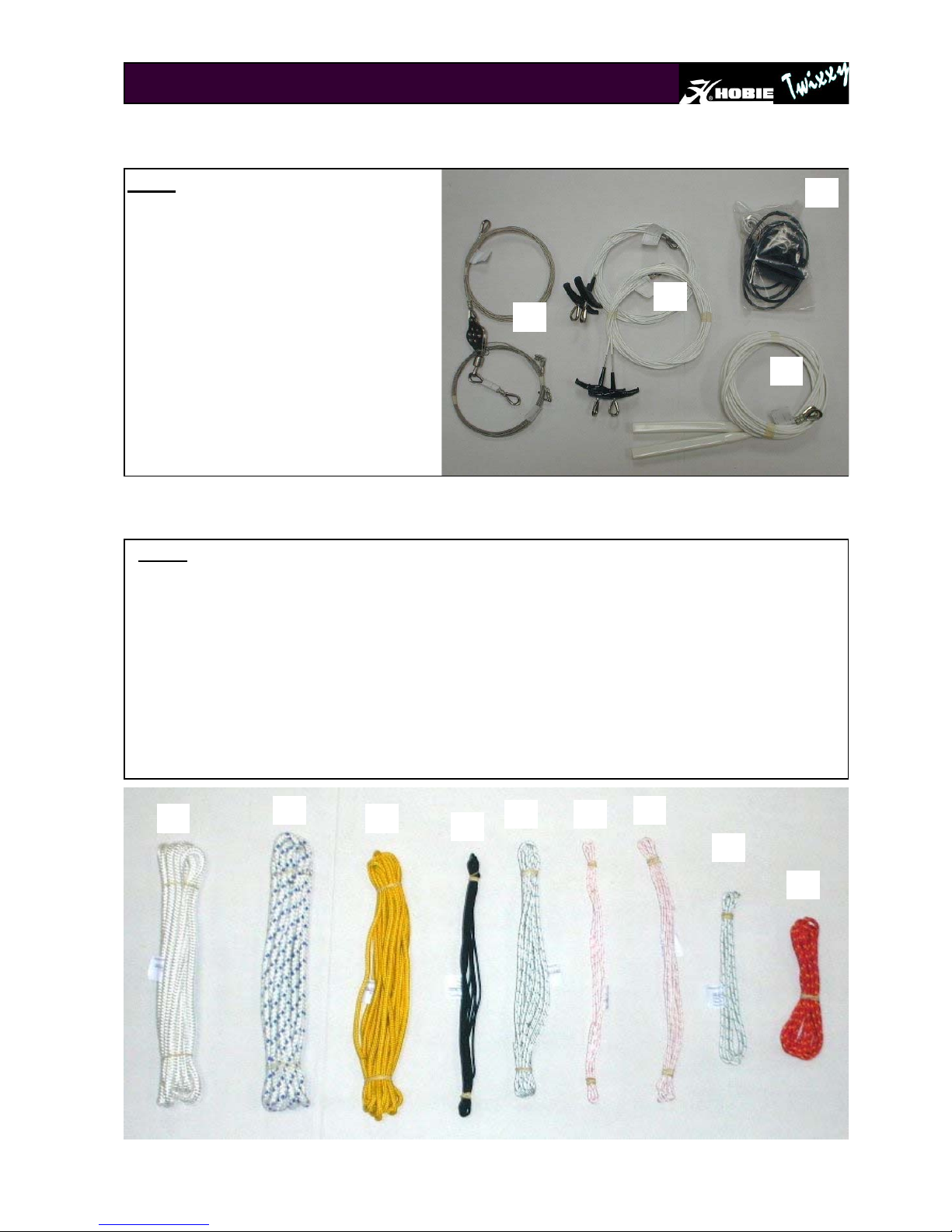
Wires
1. Shrouds with adjuster covers
2. Trapeze wires
3. Forestay, jib halyard assembly
4. Trapeze handles, rope lock and
shock cord.
Wires and ropes
3
2
1
Ropes
1. Righting line
2. Mainsheet
3. Jibsheet
4. Trampoline line
5. Main Halyard
6. Jib luff tensioning line
7. Trapeze line
8. Jib halyard
9. Cunningham
1 3
2
5
8
6
7
4
4
9
Page 4
•
4
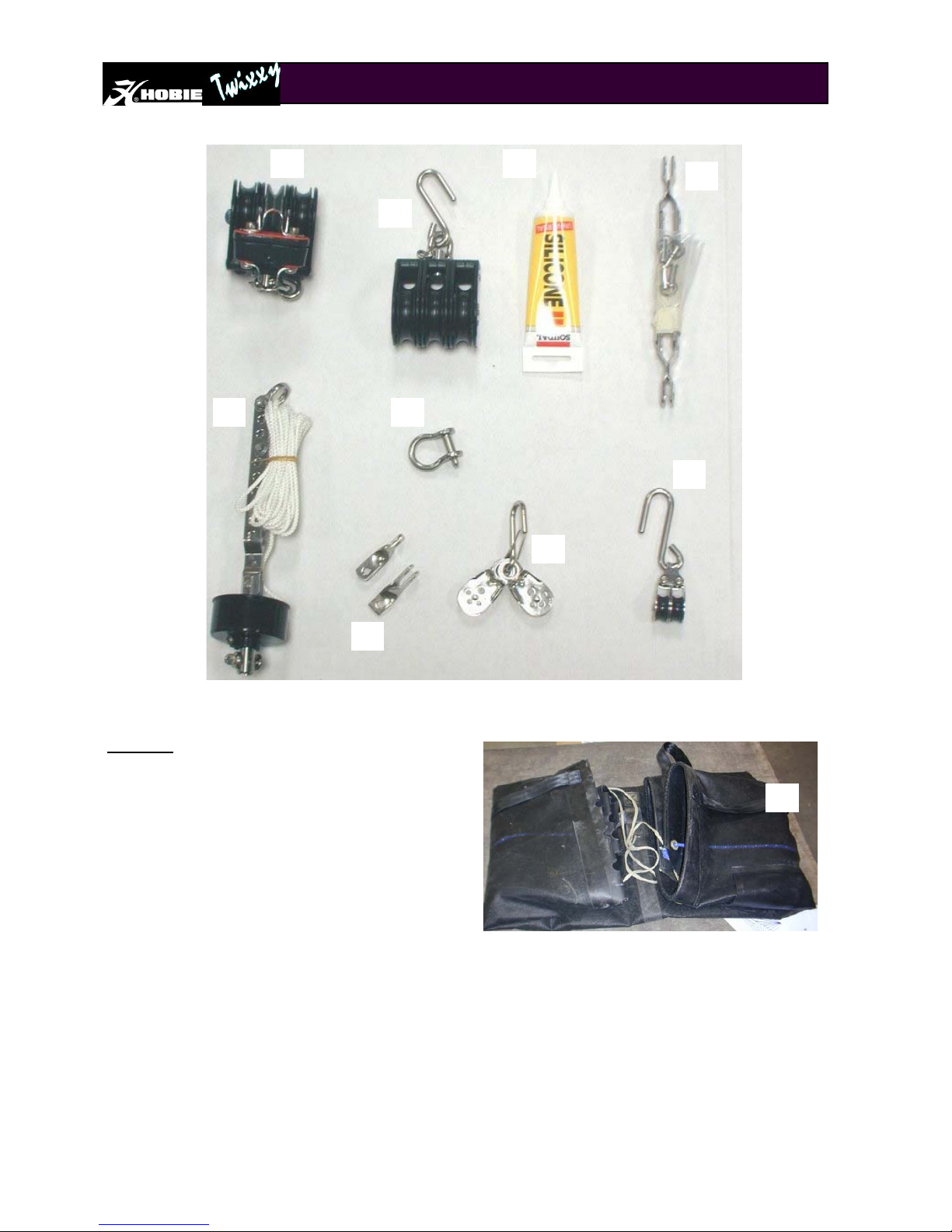
Part bag and trampoline
Part bag :
1. Mainsheet ratchet block
2. Mainsheet top block with hook
3. Silicone
4. Stay adjusters, clevis pins and split rings
5. Jib furler assembly
6. Shackle
7. Twist toggles.
8. Jib clew blocks with shackle
9. Cunningham block
10. Trampoline
Other parts not shown above :
⇒ Drain plugs (on the hulls)
⇒ Screws for bar fixing (on the bars)
1
2
4
5 6
3
7
8
10
9
Page 5
•
5
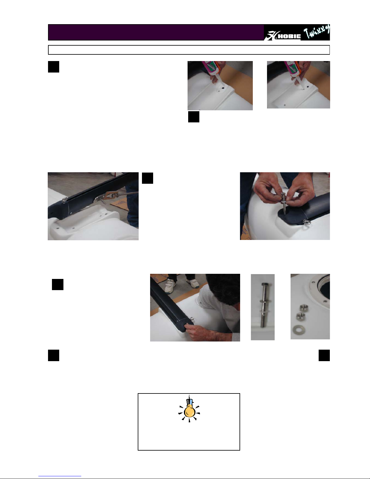
Position the hulls parallel on the ground approximately 2.5 meters apart. Prepare the front crossbar.
Unscrew the nuts off of the two 2 external head
bolts. Unscrew the nuts also off of the two internal
headless bolts.
HULLS
1
See drawing next page for positioning of bolts
All go round the boat and tighten all eight bolts.
Lift the right hull into an upright position. One person
straddles the hull to hold in position. The other on e ap plies the silicone sealant (for waterproofing) around the
bolt holes and on rivets.
Repeat the same operation for the other hull.
Repeat step 1 and 2 for the rear crossbar.
2
5 6
Taking the front crossbar, position it on
the crossbar moulding in the deck making sure that the eye strap on the bar
is facing to the rear of the boat and the
remaining headless bolt on the cross
bar fits in the hole on the deck. Insert
the long external screw.
3
Pass your hand through the inspection port to position the nuts and
washers onto the long bolt and the
headless bolt.
4
NB : Periodically check the
tightness of all 8 bolts.
Page 6
•
6
FORWARD SPREADER BAR
Forward spreader bar assembly/Montage de la barre
de maintien parallèle.
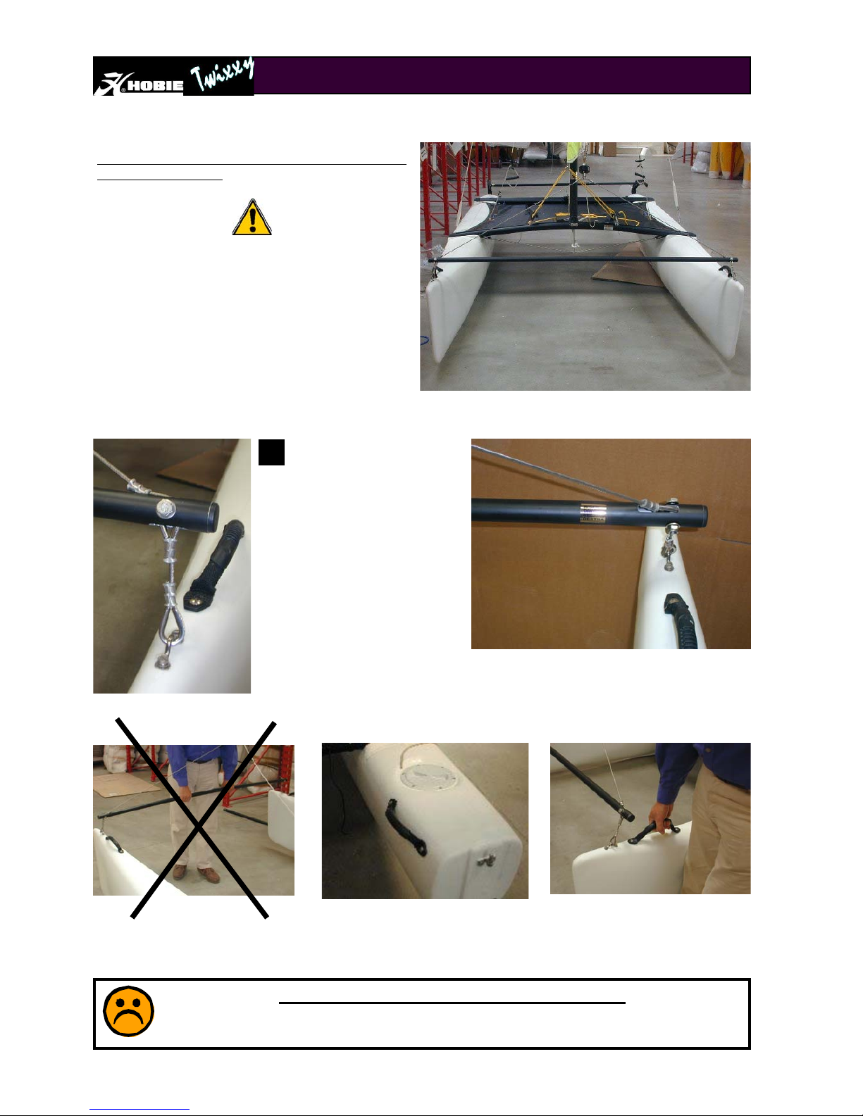
It is highly recommended to install the forward
spreader bar if the loaded weig ht is mo re th an 75
kg and wind force more than 3. Failure to respect
this recommendation may cause structural damages on the hulls that will not be covered by
warranty.
Identify the right side from the left
side of the bar (look for the stickers) and position it the right way
between the two hulls. Unscrew
one of the screws fixing the padeye on the hull and attach the bar
as shown on the photo.
VERY IMPORTANT / TRES IMPORTANT
Never use the forward spreader bar to carry the boat. Use the 4 handles
(2 at the front, 2 at the rear of the boat) to carry the boat.
1
Page 7

•
7
HULLS
Crossbar fixation
Long bolt
Short bolt
Stainless steel nut
Stainless steel washer
Plastic washer
Crossbar
Screw with head
Headless screw
Page 8
•
8
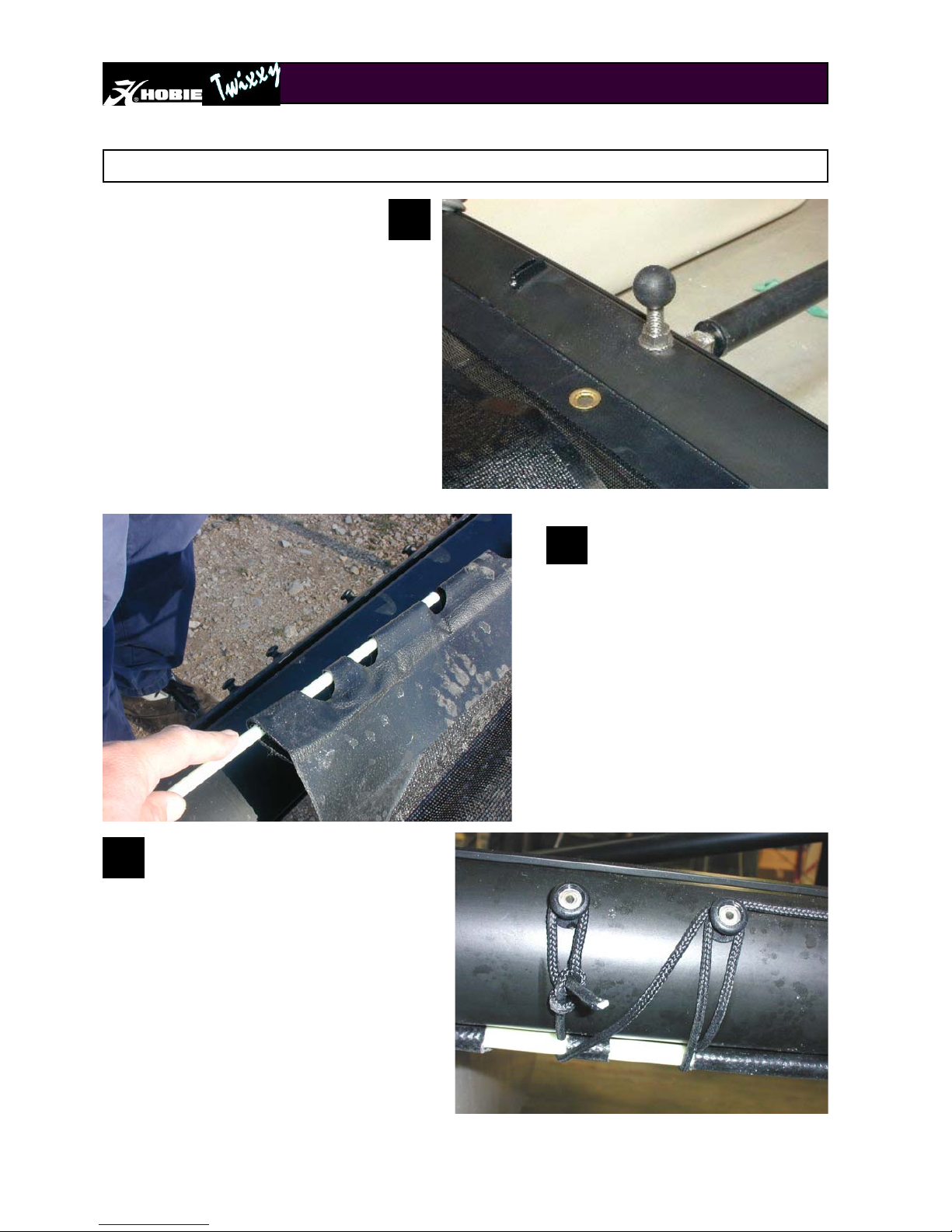
Unfold the trampoline. Note that the side tension
lines are prethreaded. Insert the front sealed bolt
rope edge into the trampoline track of the front
crossbar. Continue feeding the trampoline into the
trampoline track and position it in the centre. Line
up the grommet in the centre of the front edge of
the trampoline with the dolphin striker post. This
will position the trampoline in the centre.
TRAMPOLINE
Trampoline fitting
Commence lacing the rear of the trampoline. The
lacing line ties off on the lacing post at the left rear
of the rear beam. Pass the line around the rod and
back around the first lacing post. Lead the line
around the second lacing post and pass it around
the rod on the first trampoline cut out. Now, come
back around the second lacing post and continue
towards the third. Continue all the way across the
beam in the same fashion and tie off loosely. Do
not attempt to tighten the rear lacing too much at
this stage.
3
1
Pull the trampoline to the back of the boat
and insert the fibreflass rod into the rear
flap of the trampoline. Leave an equal
amount protruding from each side.
2
Page 9

•
9
TRAMPOLINE
Now lead the end of the line through the eyestrap on the rear of the front beam
and back through the loop. Lead the end back through the eyestrap and apply as
much tension as possible. Maintaining the tension, lead the line through the grommet and back to the eyestrap. Next, lead the line through the grommet in the front
edge of the trampoline and tie off securely. Repeat procedure for port side.
Move to the front right corner of
the trampoline. Pull on the line
as firmly as possible and tie a
bowline knot or loop in the line
as close to the trampoline edge
as possible. This will enable a
4:1 purchase to be used for tensioning. Tie off once tensioned
to secure.
Tensioning the sides : starting at the right rear corner, take the
line that emerges from the trampoline. Lead it through the eye
strap on the rear beam and then through the grommet/eyelet.
Tie it off with a bowline knot or similar.
4
5
6
Retighten rear lacing from left to right. Tie the rear lacing off securely at the eyelet posts on the right hand end
of the rear beam. NB :
It is important that the trampoline lacing is kept very tight. Check the trampoline tension
on a regular basis. Remember : all ropes streches!
7
Page 10

•
10
RUDDER ASSEMBLY
Montage du gouvernail
Identify the right rudder from the left rudder (look for
the stickers on the rudder arms). As shown, line up
the rudder pintles (metal pegs on the hulls) with the
rudder castings . Push the rudder castings down
onto the pintles.
1
Insert the retainer clip attached to the lower pintle to
lock the rudders in place. The clip will prevent the
rudders from falling off the boat in the event of capsize.
2
Page 11

•
11
Locate the tiller extension and secure it to the tiller
crossbar using the clevis pin and ring clip provided.
RUDDER ASSEMBLY
TILLER CROSSBAR AND EXTENSION
Locate the tiller crossbar and identify the left
and right hand ends. NB: the tiller crossbar (1)
locates on top of the tiller/rudder arms (2).
Locate the tiller connector kits and install as
shown on the photographs.
4
5
1
2
Page 12

•
12
Remove the main and jib halyard lines from the
ropes bags. Unroll the main halyard wire that is secured at the head of the mast. Using a bowline knot,
secure the main halyard line to the thimble at the end
of the halyard wire. Now, secure both ends at the
base of the mast.
Mast and rigging
PREPARATION OF THE MAST
1
Remove all the wires from the wires bag and unroll them.
Ensure that all twists are removed.
Locate the 8 mm tang shackle and shackle the five wires to
the mast tang, as per photograph. Ensure that the shackle
is tightened securely.
If you have a spinnaker (option), also at this stage thread
the spi halyard through the pulley near the top of the mast.
See the spi rigging diagram page 23
2
1. Trapeze
2. Shrouds
3. Pigtail, forestay & jib halyard
1
1
2
2
3
3
Page 13

•
13
At this stage, if you have a spinnaker kit,
also attach the spi ratchet block with plastic
spring as shown on the picture
PREPARATION OF THE MAST
Using a bowline knot secure the jib halyard line to the small block on the end of
the jib halyard wire. Now secure both
ends at the base of the mast.
4
Locate the Jib furler and shackle it to
the bridles using the 6 mm shackle provided. Ensure that the exit hole in the
furler is pointing at the furler cleat on the
front crossbar. Check that the screw on
the underside of the furler is tight. This
prevents the outer cover from rotating.
5
Wind the furler up in a clockwise direction. Leave enough furler line to
reach the furler cleat.
6
JIB FURLER
Next, fasten the shrouds into the stay
adjusters. To begin with, fasten the
shroud about half way up the adjuster. This
position can be adjusted later. The position
influences mast rake. Now fasten the stay
adjusters on each side of the boat. You can
pull the cover partially over the stay adjusters at this time. The assembly of the trapeze wires can wait until after you have raised the mast.
With the base of the mast facing towards the front of the
boat, lay the mast on top of the boat. (place some pading
under the mast to prevent scratching).
7
8
9
Page 14

•
14
With the person on the trampoline supporting the mast, the
other person takes the forestay and connects it to the stay
adjuster fixed to the jib furler. Pin the forestay towards the
top of the adjuster. Now, provided all the clevis pins have
the split rings fitted, the mast is supported by the shrouds
and forestay.
Now, ensure that the forestay wire is not twisted around any other wires and you
are ready for raising the mast.
Raising the mast requires two people for ease and safety. One person lifts the top
of the mast to shoulder height from behind the boat. The other person removes the
securing bolt from the mast base and positions the mast base on the mast ball
which is located at the center of the front crossbar.
Now replace the mast base securing bolt
to ensure that the mast does not pop
off of the mast ball.
Whilst one person continues to hold the top of the mast th e oth e r
then stands on the trampoline and raises the mast ensuring that
there are no overhead electrical wires. When raising the mast ensure that the shrouds and trapezes clear the rudders and do not get
caught at the back of the boat.
STEPPING THE MAST
9
10
CAUTION DANGER : ALUMINIUM MAST
STAY AWAY FROM ELECTRICAL WIRES
CONTACT WITH ELECTRICAL WIRES
MAY CAUSE DEATH
Once the forestay is attached and the mast is standing, remove the mast
base securing bolt. This bolt is only used for raising and lowering the mast
11
Page 15

•
15
Now the rig can be tensioned. One person can pull
down on a trapeze handle whilst the other person re
positions the clevis pin in the stay adjuster. Ensure
that the two shrouds are pinned at the same height
in both adjusters. If too much tension is applied it
may become difficult for the mast to rotate freely.
Check this before proceeding with raising the sail.
With the mast now secure, the trapeze
wires can be fitted with the handles, rope
locks and ajuster lines as shown in the
photograph. Use a bowline knot to secure
the line to the trapeze shock cord.
1
TRAPEZES
2
The height of trapezing can be
adjusted by changing the position of the rope lock.
Page 16

•
16
Using the straps and clips on the leech of the mainsail, secure each
batten into it’s respective pocket (as per photograph). Push the bat-
tens in reasonably hard - sufficient to remove any wrinkles
from the pocket.
NOTE : it is important to relieve the tension on the battens after each
day’s sailing. This will prolong the
life of the sail.
Unfold the mainsail and lay on a flat clean surface. Undo the set of battens and identify which batten goes in which batten pocket. Insert the battens into the pockets.
NOTE : the second batten pocket from the bottom takes the longest batten.
MAINSAIL
1
2
BEFORE RAISING THE MAINSAIL, MAKE SURE THAT THE BOAT IS POIN-
TING INTO THE WIND. IF THE WIND CHANGES DIRECTION,
MOVE THE BOAT.
Place the sail on the trampoline, the battens clips towards the back.
Undo the main halyard wire from the mast and shackle it to the head
board of the mainsail. Now, feed the bolt rope at the head of the sail
into the cut out in the sail track on
the mast.
3
Now, pull on the main halyard line
whilst feeding the sail into the
track cut out.
4
When the sail is all the way up, position the stopper on
the wire halyard so that it engages in the halyard lock.
5
Lead the halyard behind the shroud and trapeze wire and secure
at the halyard cleat on the side of the mast. Do not pull too hard
as you may disengage the halyard lock. Tuck the excess halyard
into the trampoline pocket.
6
Page 17

•
17
Unfold the jib and shackle the head onto the jib halyard with the shackle
provided. Fasten the clip at the top of the jib to the forestay wire. Pull on
the halyard and raise the sail, fastening each clip to the forestay in the
process. When the sail is raised, shackle the tack of the jib to the adjuster on top of the furler. Fasten as low as possible.
1
Use the jib luff tensioner line to replace the jib halyard.
The tensioner line can be fastened to the tack shackle,
fed up through the small block and then cleated off at the
cleat on the sail. Ensure that the line is tight and cleated
securely. Enough tension should be applied to remove
the wrinkles from the luff of the sail. The jib halyard line
can be stored in the trampoline pocket.
2
JIBSAIL
Page 18

•
18
Attach the jib clew blocks to the clew of the jib using
the snap hook provided.
3
Thread the jib sheet line through the jib sheet blocks.
Fasten the sheet to the top of the blocks using a
bowline knot. Ensure that there are no twists in the
sheet and that the sheet is led behind the mast.
4
The jib can now be furled by
pulling on the furler line and
cleating it off in the jam cleat.
The jib will not furl fully if the
jib sheet is cleated on.
5
JIBSAIL
Page 19

•
19
Fasten the mainsheet ratchet block onto the top of the main
traveller. The mainsheet system is now ready to be headed to
the clew of the mainsail. NB : It is best to leave the top block
unhooked until the boat is in the water.
MAINSHEET SYSTEM
Position the triple ratchet block and the triple top
block as indicated in the photograph.
Carefully follow the threading sequence shown in the
photographs and you should have no problems.
There should be no crossovers or twists in a properly
threaded 6:1 system.
1
2
Thread the tail of the mainsheet line through the travellet cleat and fairlead of the traveller car and then
secure with a figure 8 knot at the eyesstrap on th e aft
edge of the rear crossbar.
3
Page 20

•
20
Cunningham/Righting line
Cunningham
⇒ Locate the cunningham line and the cunningham double block with hook
⇒ Attach the hook to the tack of the mainsail.
⇒ Fasten one end of the cunningham line to the cleat mounted at the bot-
tom of the sail track on the mast.
⇒ Pass the other end through one of the sheaves on the block and then
back down around the cleat.
⇒ Thread the line through the remaining sheave and then pull down on the
line to remove the wrinkles from the front of the mainsail. Tie the line off
on the cleat.
⇒ The stronger the wind, the more cunnin-
gham tension is required.
1
Righting Line
Tie a knot about 35 cm from the end of the line and pass the
short end down through the grommet at the contre front of
the trampoline.
Then pass the line through the eyestrap mounted underneath
the mast step and tie a figure 8 knot in the end.
Now, stow the rest of the righting line in the trampoline po-
cket.
A knot in the righting line just above the grommet
will prevent the righting line from slipping down and
dragging in the water.
2
Page 21

•
21
Safety device
Mast float device (OPTION)
As serial or optional equipment, the mast float devise is already mounted. You just need to
fit it on your mast head (see step 3). If it is not mounted, follow steps 1 to 3 below.
This device prevents the mast from sinking in case of capsize thus allows easy righting.
1- Unscrew the four screws that
are on the device.
2- Adjust the alu plate so that the
holes fit the four holes on the device and fix it with the screws.
3- Fix the device on the mast
head using the bolt and the two
washers as shown on the photo.
Safety Cord
While sailing, the safety cord on the trampoline (blue line on the photo, that may be of a different colour) prevents the crew from falling off of the cat, and allows easy righting in case of capsizing.
On the trampoline Under the trampoline
Page 22

•
22
SPINNAKER (Option)
Attaching the spi pole
Fix the base of the pole onto the
spi pole connection fitting in the
centre of the front cross beam.
1
Bridles
Next, attach the two bridle wires
to each side of the bows of the
boat with the shackles supplied.
2
Tension du tangon
The pole then is tensioned so it sits
above the bow spreader bar as shown.
To do that, take the pole support line. Attach one end onto one of the jib furler
bridle thimble, lead it under the pole and
back up to the other jib furler bridle
thimble.
3
Page 23

•
23
SPINNAKER (Option)
Drisse, cordages et écoutes
Once the pole is attached, you can thread the lines.
1. Take the spi halyard that is attached at the cleat at the bottom of the mast.Attach one end to the spi head
as shown on the drawing.
2. Take the spi luff tensioning line, and fix it to the spinnaker tack point, then through the pulley on the pole,
then in the other pulley and attach the end of the line on the padeye under the pole pulley. (see photo 2 hereunder)
3. Attach the spi sheet to the spinnaker clew point and lead it through the pulleys as shown on the drawing
hereunder.
4. Tie the spi bag on the trampoline using the 4 attachment points located on
the trampoline. Once the bag is attached, pack the spi in the bag.
4
1
2
3
4
Page 24

•
24
TRUMPET SPINNAKER (Option )
Page 25

•
25
Hawaïan righting system
Take the shock cord supplied in the kit. Tie it with a tight knot onto the first ring supplied in the
kit. Pass the shock cord through the first pulley used in step 1, The shock cord passes then
through the eyelet at the center of the trampoline directly behind the mast step ball and back
into the eyelet of the trampoline. Then pass the shock cord through the second pulley used in
step 1 and tie it to the second ring supplied.
Tie the 2 small black pieces of rope onto the trampolin e la-
cing at each end of the rear cross beam. To the other end of
each rope tie the small pulley supplied in the kit.
Take the righting rope (12 mm
yellow rope in the rope bag)
and pass it around the fixation
of the dolphin striker under the
front cross beam. Tie a knot in
the rope.
3
1
2
Named after the Hawaiian’s who are generally pretty relaxed people the Hawaiian righting system combines
safety, speed and comfort when righting your capsized catamaran.
Pass the rope through the first
ring, then around the dolphin
striker post in the center of the
front cross beam, then through
the second ring. Fix then this
rope to the dolphin striker on
the opposite side and secure
the rope.
4
From above From below
Page 26

•
26
TO READ CAREFULLY BEFORE SAILINGSAFETY AND ADVICE
♦
Whether on land or on the water, watch for overhead power lines . Contact with po-
wer lines can cause serious injury or death.
♦
DO NOT sail while under the influence of alcohol and/or drugs
♦
Only sail in conditions in which you feel comfortable and where you feel confident that
you can safely sail the boat. Never go out in conditions beyond your ability
.
♦
Everyone on board should wear a life jacket at all times .
♦
If you are in the water, remain in contact with the boat, even if it is capsized. A sailboat
can drift away faster than a person can swim.
♦
Never sail without a righting line.
♦
Wear appropriate clothes . Wear a wet suit or dry suit in cold weather or cold water
conditions.
♦
Learn the right of way rules and when in doubt, give way to others.
♦
When not sailing, always keep the boat pointed into the wind whether in the water
or on the beach.
♦
Read the instruction manual carefully.
♦
Make sure everyone on the boat reads and understnads these safety instruc-
tions .
♦
ALWAYS check that the drain plugs are screwed in before launching your catamaran.
 Loading...