

Hobie SPORT CRUISER 21 User Manual

WELCOME TO THE
HOBIE WAY OF LIFE
Congratulations on the purchase of your new HOBIE 21 Sport Cruiser and welcome to the HOBIE® sailing family. The beauty
of the 21 Sport Cruiser is that a single adult can sail it at top performance - and a crew of four can cruise in comfort.
We offer this manual as a guide to increased safety and enjoyment of your new boat. The purpose of this publication is to
provide easy, simple and accurate instructions on how to get your Hobie 21 SC ready for the water. Please read them
carefully and familiarize yourself with the boat and all of the parts spread before you.
Whether you are a new sailor or a veteran of many years, we recommend that you read this thoroughly before your first sail
and TRY IT OUR WAY FIRST! If you are new to sailing, this manual alone is not intended to teach you how to sail. There are
many excellent books, videos and courses on the safe handling of small sailboats. We suggest that you contact your local
sailboat dealer, college or Coast Guard Auxiliary for recommendations.
Watch for overhead wires whenever you are rigging, launching, sailing or trailering with the mast up. CONTACT OF THE
MAST WITH POWER LINES COULD BE FATAL! Be certain that the rigging area and the area that you will be sailing in are
free of overhead power lines. Report any such power lines to your local power authority and sail elsewhere.
We take pride in presenting the Hobie 21 SC to you and hope that you'll take as much pride in owning her.
Fair winds and good sailing!

1
This assembly manual takes you stepby-step through the setting-up and
sailing of your new HOBIE 21 SC.
This manual will help you understand
each part in detail.
Setting up your Hobie 21 SC PAGE
Framing the Hulls..............................2-3
Lacing the Trampoline, Main................4
Bow Spreader ......................................5
Lacing the Trampoline, Front ...............5
Cat Cabin .............................................6
Wings ................................................6-7
Rudders................................................8
Tiller Cross Bar and Extensions...........8
Centerboards........................................9
Drain Plugs.........................................10
Mast...............................................10-11
Preparing the Mast........................12-14
Mast Stepper .................................15-16
Boom Installation................................17
The Jib ..........................................18-19
The Main Sail ................................19-20
Downhaul and Outhaul.......................20
Hull Storage Hatches .........................21
The Tent (option)...........................21-22
Motor Mount (option)..........................22
Jennaker (option) ...............................26
Sailing your Hobie 21 SC ...........PAGE
Topping LIft...............................................23
Furling the Mainsail..................................23
Righting the Cruiser .................................23
Trailering...................................................24
Comptip Maintenance..............................24
Routine Maintenance .........................24-25
Safety........................................................25
Sailing Basics......................................27-30
Safety tips ..................................Back page
HOBIE 21 SPORT
CRUISER ASSEMBLY MANUAL
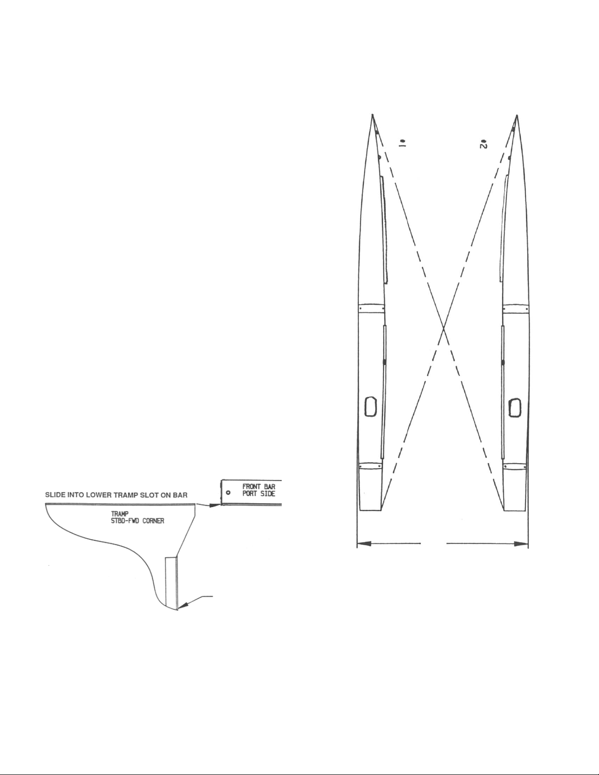
I. FRAMING YOUR BOAT.
l.l USING THE CARDBOARD CRADLES
FROM THE SHIPPING BOX, PLACE HULLS
PARALLEL TO ONE ANOTHER SO THAT
PHANTOM LINES 1 AND 2 ARE OF EQUAL
DISTANCE. WIDTH APART = 8'6" (FIGURE
1)
1.2A INSTALL MAIN TRAMPOLINE INTO
LOWER SLOT OF FORWARD CROSS BAR.
(FIGURE 2)
1.3 INSTALL FRONT CROSSBAR (SEE
NEXT PAGE FOR DIAGRAM)
NOTE - READ ALL INSTRUCTIONS PRIOR TO ASSEMBLY.
TRAMPOLINE INSTALLATION
SLIDE INTO TRAMP
TRACKS BEFORE
MOUNTING THE XBAR TO THE
HULLS.
8’ 6”
FIGURE 1
FIGURE 2
2
3
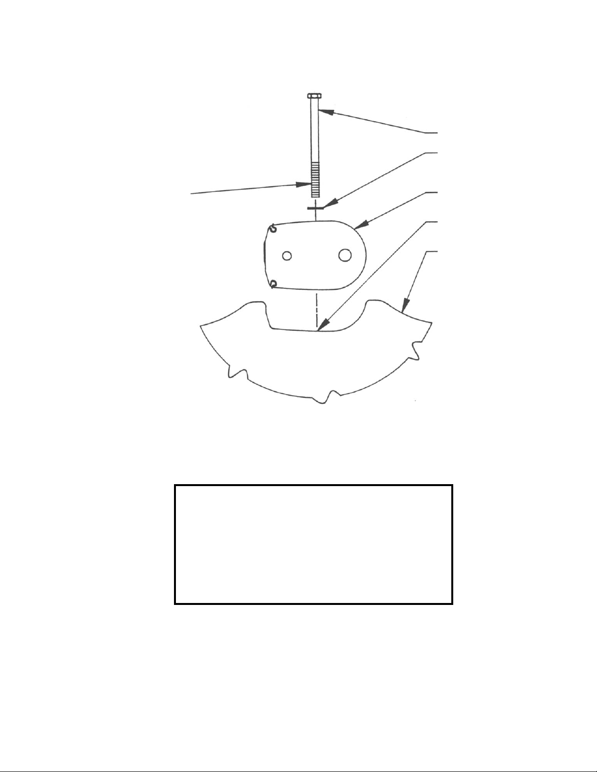
-CAUTION-
If BOLTS FEEL LIKE YOUR FORCING THEM
TO THREAD, BACK THEM OUT AND CHASE
TAPPED HOLES WITH A 3/8" -16 TAP.
FORCING THREADING WILL DAMAGE THE
BOLT AND TAPPED HOLE THREADS.
APPLY ANTI SEIZE
PRIOR TO INSTALLING
(PREVENTS THREAD
DAMAGE)
(4” BOLTS
INSTALL IN
REAR BAR)
2. INSTALLING CROSS BAR BOLTS
Applies to both front and rear cross bars
3/8” X 3/4” WASHERS
FROM RIG KIT
FRONT BAR STDB OUTBOARD
APPLY RTV SEALANT
AROUND HOLES PRIOR
TO INSTALLATION
STBD HULL - OUTBOARD
FIGURE 3
4
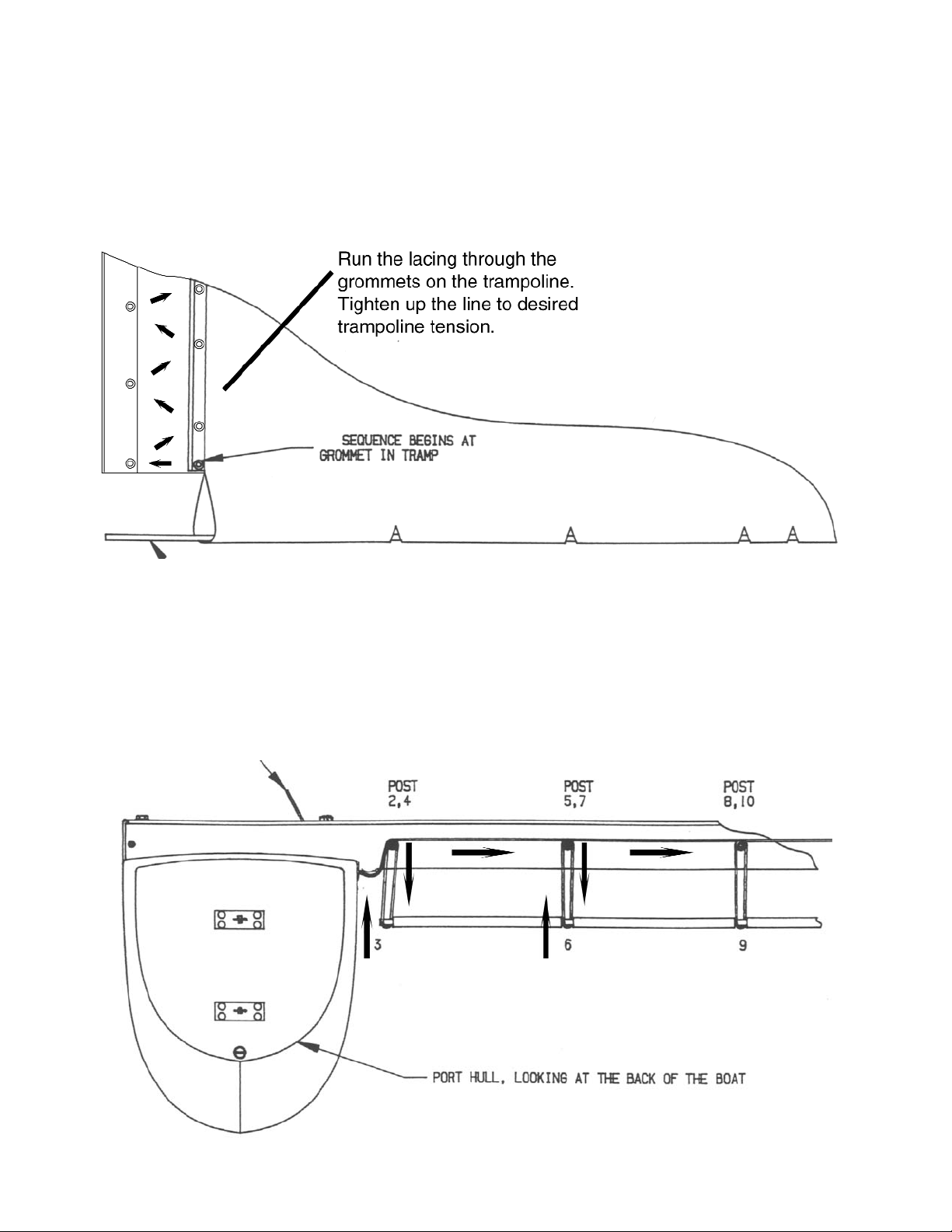
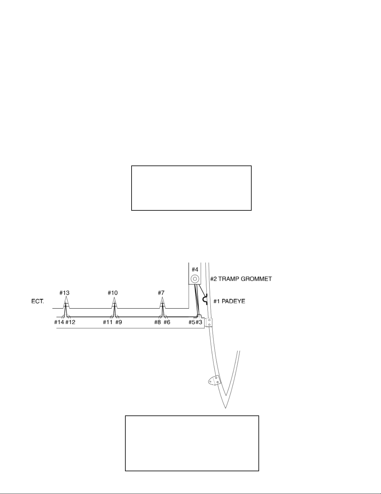
3. LACING YOUR TRAMPOLINE
LINE STARTS AT GROMMET
IN TRAMP W/ A BOWLINE
KNOT.
3.1 Before lacing, slide the tramp into the tracks in both of the hulls. Be sure to slide back as
far aft as possible. Using soapy water helps with the installation of the tramp.
3.2 Place tramp lace bar in tramp as shown below. (FIGURE 4)
3.3 Follow the rear X-bar lacing diagram (Figure 5)
NOTE: Tighten tramp to individual preference. Do not use any tramp tightening device. This
may cause damage to the tramp.
INSERT ROD IN AFT LOOP OF THE TRAMP AS SHOWN
FIGURE 5
FIGURE 4
5
4. BOW SPREADER INSTALLATION
Install the bow spreader bar assembly with the open slot towards the aft of
the boat using the four round head bolts provided.
5. FRONT TRAMPOLINE INSTALLATION
Insert the forward trampoline into the upper groove of the front X-bar. The trampoline folds over the
front X-bar and then inserts into the forward trampoline track. Slide the tramp track forward (leave
loose until cat cabin is fully installed). After the cat cabin has been fully tensioned down...pull the
tramp forward until taunt to slugs in forward spreader bar.
INSTALLATION HINT:
USE SOAPY WATER TO HELP
INSTALL THE TRAMPOLINE.
FOLLOW THE LACING SEQUENCE SHOWN ABOVE
(TIE BOWLINE KNOT HERE)
FIGURE 6
6. 21 SPORT CRUISER FWD. TRAMP LACING INSTRUCTIONS
REMINDER:
DO NOT TENSION FRONT
TRAMPOLINE UNTIL CAT CABIN
IS FULLY TENSIONED DOWN.
6
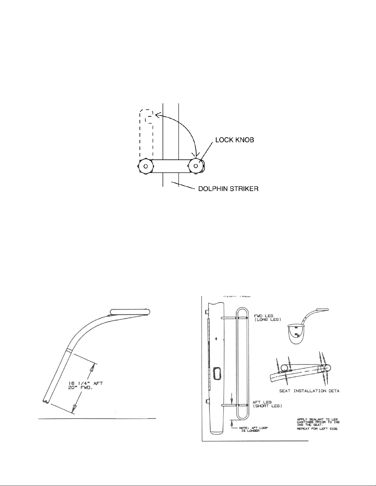
8. WINGS
8.1 Identify the left and right wing assemblies.
Red Dot = LEFT
Green Dot = RIGHT
8.2 Mark the legs with tape as shown. These
points indicate full and complete insertion of
the legs into the hull. (FIGURE 8)
8.3 Put the right wing legs into the sockets and
place the right seat onto the legs. All parts are
pre-drilled so the holes should line up properly.
Rivet the seat onto the legs using rivets and
rivet caps. (FIGURE 9)
FIGURE 8
FIGURE 9
7. CAT CABIN
(FRONT TRAMPOLINE MUST BE LOOSE) POSITION BOX OVER FRONT CROSSBAR. EASE
DOWN OVER CROSSBAR. STUDS IN THE BOTTOM OF CAT CABIN PASS THRU THE
TRAMPOLINE SLOTS. REMOVE TWO BLACK PLATES, FOUR BLACK LOCK KNOBS AND LOCK
WASHERS FROM RIG KIT. PLATES INSTALL SO THAT THE CABIN IS REMOVABLE FROM
BELOW THE BOAT BY HAND.
FIGURE 7
7
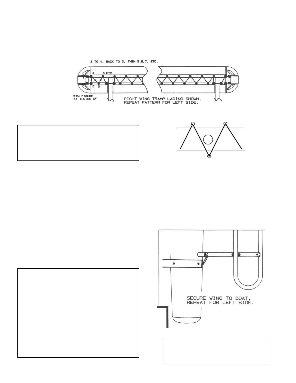
8.4 Lace the wing tramp as shown. (FIGURE 10)
8.6 Before sailing, secure the wing legs on the
hull with a short piece of line. (FIGURE 12)
NOTE: INSTALL WING TRAMPS SO
LACE LINES DO NOT INTERFERE WITH
CUP HOLDERS (FIGURE 11)
WARNING:
WINGS WILL NOT FLOAT!
CAUTION
It is very important that the wings are
completely inserted when sailing or
whenever any load is applied to them.
Failure to completely insert the wings will
result in hull and/or wing damage. You
have inserted the wings completely when
the band of tape on the outboard side of
each insertion tube aligns with the top of
the hull deck.
8.5 To insert the wings, simply work the leg
tubes into the hull sockets an inch or so at a
time. Push one leg of the wing into the tube,
then the other and continue alternating until
both sides are completely inserted. If the wings
cannot be easily inserted using this system,
check the end caps and sockets for debris
(such as sand), improper fitting or metal burrs.
FIGURE 10
FIGURE 11
FIGURE 12
8
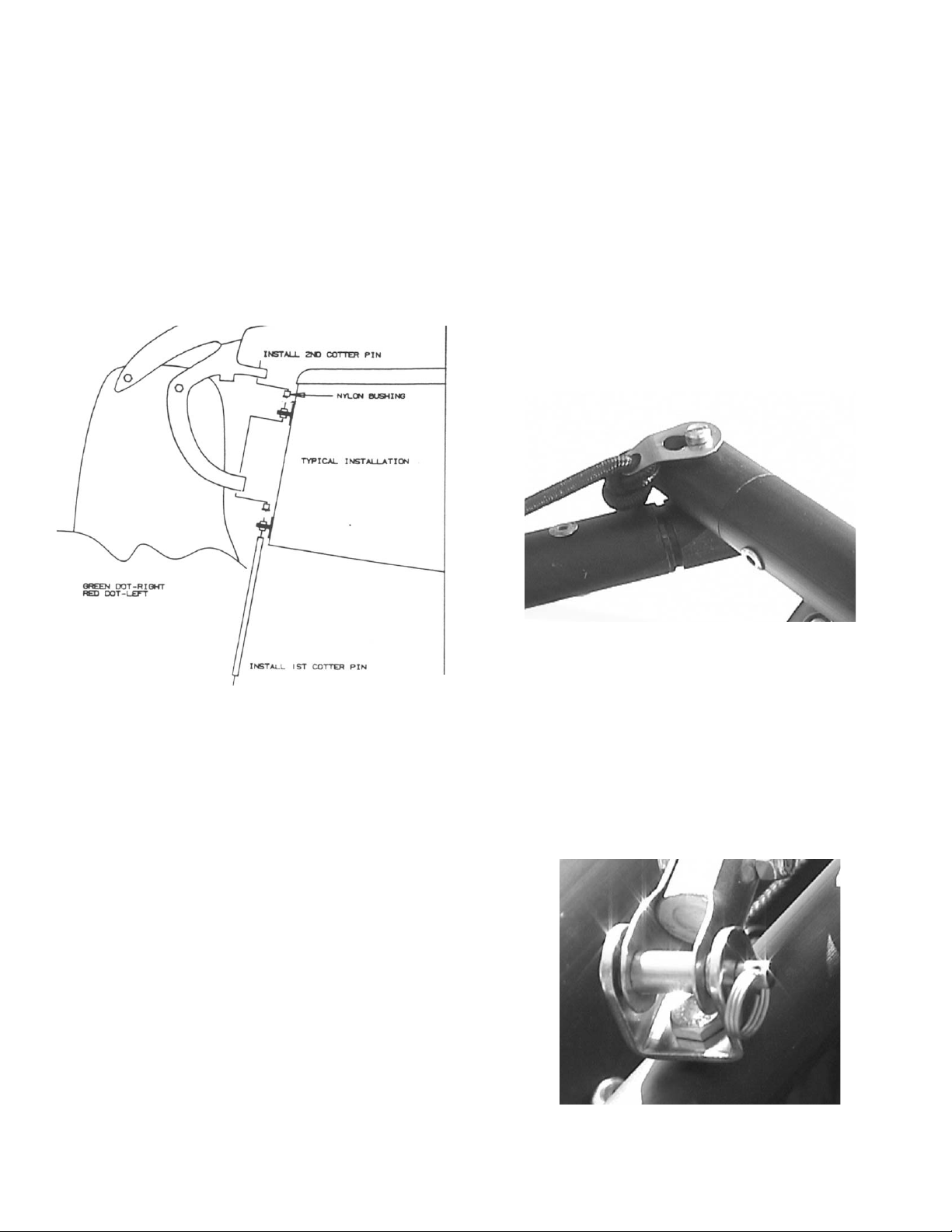
9. RUDDERS
9.1 Identify the left and the right rudder
assemblies.
Red Dot = LEFT
Green Dot =RIGHT
9.2 Insert one nylon bearing into the bottom of
each hole in the rudder castings. (FIGURE 13)
9.3 Put one cotter pin on each rudder pin.
(FIGURE 13)
9.4 Set the casting on the gudgeons. (FIGURE
13)
9.5 Push the rudder pin UP through the lower
gudgeon and make sure to place a stainless
steel washer between the gudgeon and the
nylon bearing in the casting. (FIGURE 13)
9.6 Repeat step 4.5 for the upper gudgeon.
(FIGURE 13)
9.7 Secure the top of the rudder pin with a
second cotter pin. (FIGURE 13)
9.8 Repeat for the other rudder assembly.
10. TILLER CROSSBAR
10.1 Place the red dot end (left) of the tiller
crossbar on the red dot (left) rudder.
10.2 Insert the tiller crossbar onto the rudder
arm pin so that the crossbar sets on top of the
arm.
10.3 Capture the tiller arm to the tiller crossbar
with the keyhole retainer clip on the tiller arm.
(FIGURE 14)
10.4 Attach the tiller extension to the yoke of
the tiller crossbar by inserting the clevis pin
and retaining ring. (FIGURE 15)
FIGURE 13
FIGURE 14
FIGURE 15
 Loading...