

Page 1
- !." I!_'
: ';..'
HOLDER@ 12
-
I, ': 1_(, 1
,
ASSEMBI~~ =
'\~ :" '
"
Page 2
A
;. -
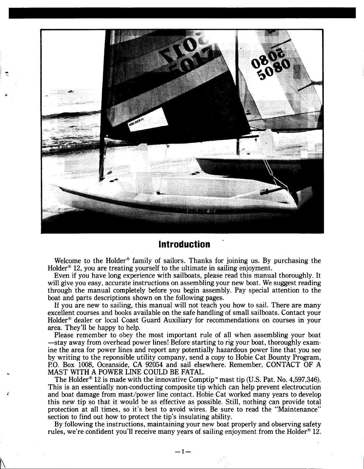
Introduction
Welcome to the Holder@ family of sailors. Thanks for joining us. By purchasing the
Holder@ 12, you are treating yourself to the ultimate in sailing enjoyment.
Even if you have long experience with sailboats, please read this manual thoroughly. It
will give you easy, accurate instructions on assembling your new boat. We suggest reading
through the manual completely before you begin assembly. Pay special attention to the
boat and parts descriptions shown on the following pages.
If you are new to sailing, this manual will not teach you how to sail. There are many
excellent courses and books available on the safe handling of small sailboats. Contact your
Holder@ dealer or local Coast Guard Auxiliary for recommendations on courses in your
area. They'll be happy to help.
Please remember to obey the most important rule of all when assembling your boat
-stay away from overhead power lines! Before starting to rig your boat, thoroughly examine the area for power lines and report any potentially hazardous power line that you see
by writing to the reponsible utility company, send a copy to Hobie Cat Bounty Program,
P.O. Box 1008, Oceanside, CA 92054 and sail elsewhere. Remember, CONTACT OF A
.. MAST WITH A POWER LINE COULD BE FATAL.
The Holder@ 12 is made with the innovative ComptipTM mast tip (U.S. Pat. No. 4,597,346).
; and boat damage from mast/power line contact. Hobie Cat worked many years to develop
This is an essentially non-conducting composite tip which can help prevent electrocution
this new tip so that it would be as effective as possible. Still, nothing can provide total
protection at all times, so it's best to avoid wires. Be sure to read the "Maintenance"
section to find out how to protect the tip's insulating ability.
By following the instructions, maintaining your new boat properly and observing safety
rules, we're confident you'll receive many years of sailing enjoyment from the Holder@ 12.
-1-
~
Page 3
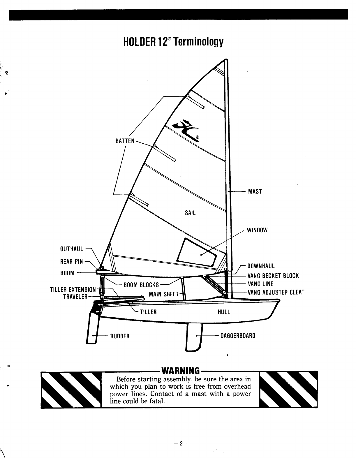
HOLDER 12@ Terminology
~
..
MAST
WINDOW
OUTHAUL
REAR PIN DDWNHAUL
BOOM VANG BECKET BLOCK
BOOM BLOCKS VANG LINE
TILLER EXTEN
TRAVELE MAIN SHEET VANG ADJUSTER CLEAT
HULL
DAGGERBOARD
.
'£
WARNING
i which you plan to work is free from overhead
Before starting assembly, be sure the area in
power lines. Contact of a mast with a power
line could be fatal.
1\
-2-
Page 4
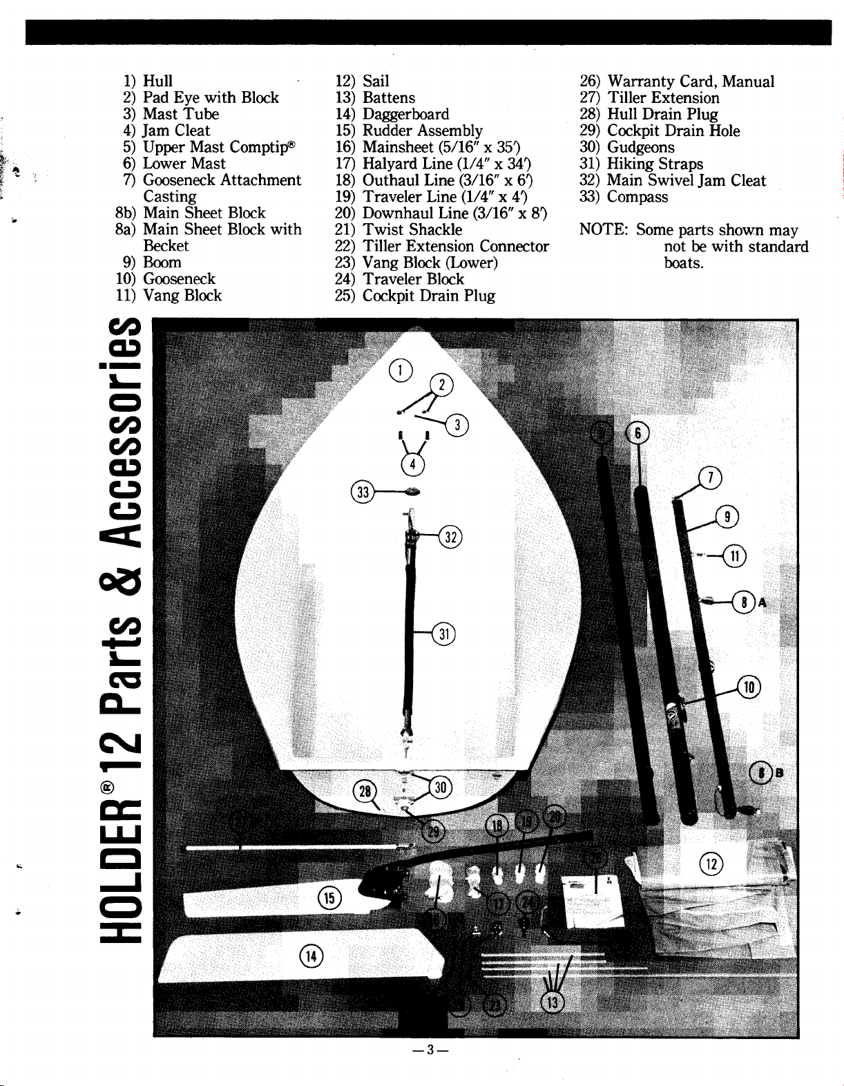
1) Hull 12) Sail 26) Warranty Card, Manual
2) Pad Eye with Block 13) Battens 27) Tiller Extension
3) Mast Tube 14) Daggerboard 28) Hull Drain Plug
4) Jam Cleat 15) Rudder Assembly 29) Cockpit Drain Hole
! 5) Upper Mast Comptip@ 16) Mainsheet (5/16" x 35) 30) Gudgeons
~,~ 6) Lower Mast 17) Halyard Line (1/4" x 34) 31) Hiking Straps
~.. ; 7) Gooseneck Attachment 18) Outhaul Line (3/16" x 6) 32) Main Swivel Jam Cleat
[ Casting 19) Traveler Line (1/4" x 4) 33) Compass
'- 8b) Main Sheet Block 20) Downhaul Line (3/16" x 8)
8a) Main Sheet Block with 21) Twist Shackle NOTE: Some parts shown may
Becket 22) Tiller Extension Connector not be with standard
9) Boom 23) Yang Block (Lower) boats.
10) Gooseneck 24) Traveler Block
11) Yang Block 25) Cockpit Drain Plug
~
=
.- 0
6 ~
CIJ I ~~-..~
~ Q)
~ @ ~
<
~
c..
N
~:
.. C
.. C
CIJ
~
L..
ca
.
@
u.J
-J
::~
-3-
Page 5
ASSEMBLY INSTRUCTIONS
I. The Plugs II. Traveler Assembly
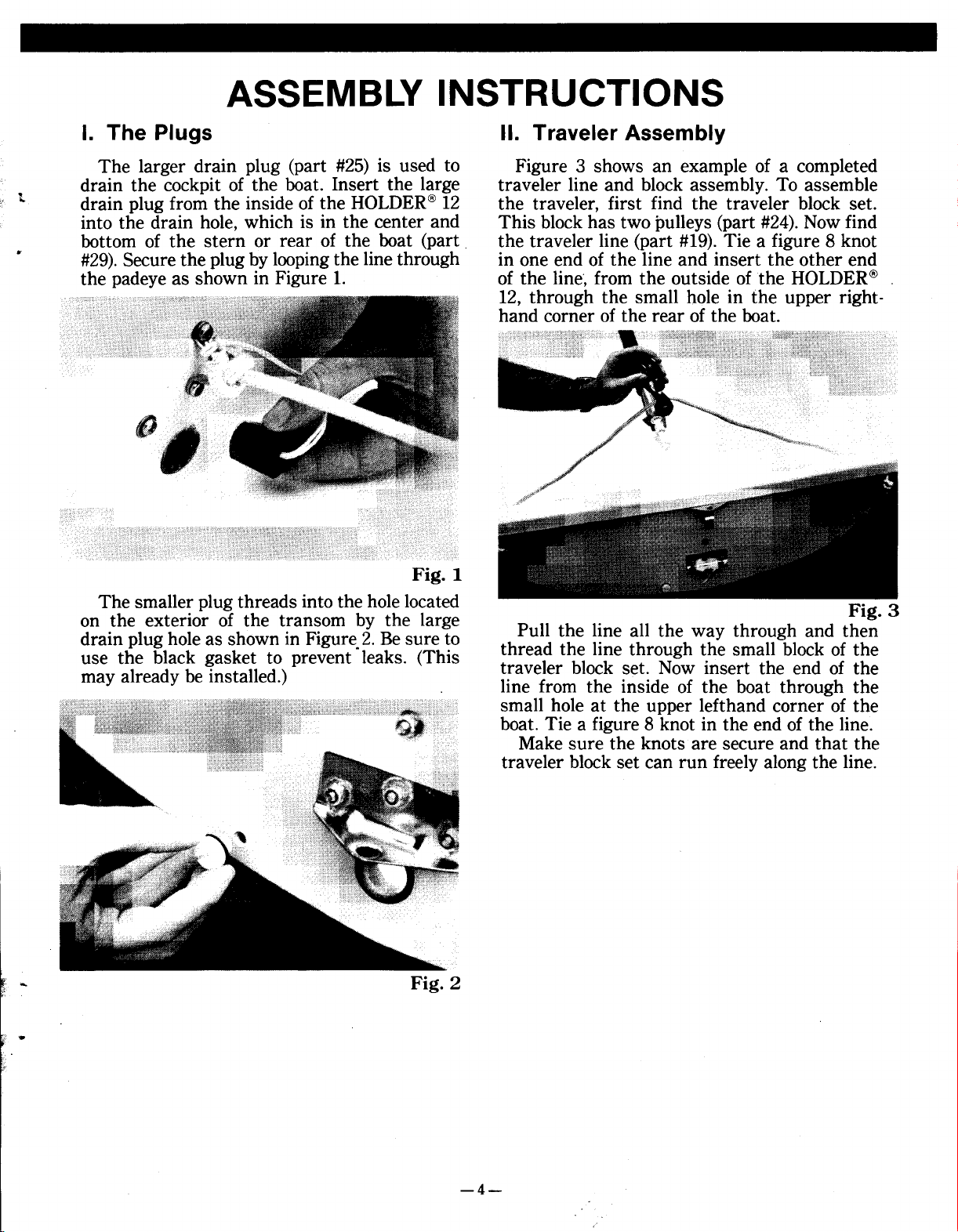
The larger drain plug (part #25) is used to Figure 3 shows an example of a completed
t drain plug from the inside of the HOLDER@ 12 the traveler, first find the traveler block set.
. #29). Secure the plug by looping the line through in one end of the line and insert the other end
drain the cockpit of the boat. Insert the large traveler line and block assembly. To assemble
into the drain hole, which is in the center and This block has two pulleys (part #24). Now find
bottom of the stern or rear of the boat (part the traveler line (part #19). Tie a figure 8 knot
the padeye as shown in Figure 1. of the line', from the outside of the HOLDER@ ,
12, through the small hole in the upper righthand corner of the rear of the boat.
Fig. 1
The smaller plug threads into the hole located F. g 3
on the exterior of the transom by the large. 1 .
drain plug hole as shown in Figure.2. Be sure to Pull the l~ne all the way through and then
use the black gasket to prevent leaks. (This thread the lIne through t.he small block of the
may already be installed.) t:aveler block ~et: Now Insert the end of the
.. Fig. 2
lIne from the InsIde of the boat through the
small hole at the upper left hand corner of the
boat. Tie a figure 8 knot in the end of the line.
Make sure the knots are secure and that the
traveler block set can run freely along the line.
..
-4-
Page 6

III. Mast and Sail Assembly
A. Standard and Special Edition
The mast is in two sections (part #'s 5, 6).
The bottom section displays the warnings
against sailing and assembling near overhead
t wires and power lines. Before raising the mast,
check again that you are in a safe area and
W Insert the top section of the mast into the
always remember this warning.
bottom section, making sure the tab on the rib
fits securely into the notch at the opening, as
shown in Figure 4.
Fig. 6
To make rigging the boat easier, point the
boat into the wind to keep the sail from twist-
ing around the mast. Now insert the mast as
shown in Figure 7.
Next, find the three sail battens (part #13)
and insert them into the batten pockets in the
sail. To do this, push the batten in and then -.
slightly down with your thumb and forefinger -.
(Figure 5). The batten should slide in easily.
~
f ..
r
~ B. Standard Sail
Insert the top of the mast into the sail sleeve
at the front of the sail and pull the sail over the
mast as far as possible, making sure the sleeve
doesn't twist around the mast (Figure 6).
At the bow, or front of the boat, is the mast
socket. It is a deep hollow area. You are now Fig 8
ready to insert the mast into the mast socket. .
Fig. 4
Fig. 7
C. Special Edition Sail (Zipper Luff)
Locate halyard line (part #17) and run it
through the mast head {Figure 8) using a bowline knot; attach the line to the head of the sail
Fig. 5
-5-
Page 7

(Figure 9). Place the sail in the cockpit and
connect the zipper by wrapping the luff sleeve
around the mast. Fold the webbing around to
th~.velcro@~tt~chmeD.tp()int (Figure 10).
t.
.
Fig. 9
Fig. 10
Make sure the halyard is on the inside of the
luff sleeve. Now hoist the sail by pulling down
on the halyard and closing the zipper simultaneously. When the sail is fully raised, close
the Velcro@ cover webbing and cleat off as
shown (Figure 11).
.
"
! Oc
,
~
~
t,
J:~'""
,
Fig. 11
-6-
Page 8

IV. Boom Assembly V. Outhaul, Downhaul and
The HOLDER@ 12 boom (part #9) IS sImple to
use, yet it is one of the most advanced designs Locate the outhaul line (part #18) and the
available on a sailboat of this size. To connect downhaul line (part #20). Attach them to the
the boom, slide the end where the hole is onto padeyes on the deck (part #2), using a bowline
;. the gooseneck (Figure 12). Then take the clew knot (Figure 14). (It does not matter which side
of the sail in one hand and the outhaul "S" you use.) Run the outhaulline through the outhook in the other, and hook into the grommet haul block, down to the block connected on the
~ (Figure 13). You are now ready to connect the padeye and exit through the jam cleat (part #4).
outhaulline. Follow the same procedure, but from the other
. . Vang Assembly
side, and go through the grommet at the foot of
the sail for the downhaul. Both shown (Figure
15). To connect the vang, start by attaching the
twist shackle (part #21) to the lower mast strap
and the vang block (part #23) (Figure 16). Run
the line as shown (Figure 17). NOTE: Vang line
should be attached to the boom. Standard boats
do not have vang.
I? .-
,
"ft
1 .
Fig. 14
.
Fig. 13
--
~
..
,
,
Fig. 15
-7-
Page 9

VI. Mainsheet Assembly
Locate mainsheet (part #16). Take one end of
the mainsheet and tie it to the small block
hanging at the rear of the boom with a bowline
(Figure 18). Run the free end through the large
r block of the traveler block set and then back up
to and through the .small block hanging at the
»
rear of the boom.
Fig. 16
Fig. 18
Now run the free end of the mainsheet for-
ward along the boom. Run the line through the
~ circular strap attached to the boom and then
run the line through the block attached to the
~ boom just forward of the strap.
. Fig 17 Continue the line forward and then down
. through the mainsheet block (part #32) at-
tached to the bottom of the hull behind the
mast and the daggerboard slot. Tie the free end
of the line in a figure 8 knot about 6 inches
from the end. Shown, Figure 19.
~:::j
~
.. Fig. 19
-8-
Page 10

VII. Rudder and DaggerboardSpecial Notes
To attach the rudder assembly (part #15) to Using the Kick-up Rudder
the boat, align the pins on the rudder with the The kick-up rudder on the HOLDER@ 12
fittings (~art ~30) on the transom. Make sure permits the rudder to do all of the hard work by
- t~at the tiller IS placed ~nderneath the tr~ve.ler using the over-center cam principle. Snapping
- lIne. Make sure the clIp ?n th,e upper fIttmg the end of the tiller puts the rudder in motion
engages the top rudder pm (FIgure 20). Now and causes the rudder to raise or lower itself as
. push down. needed. Do not try to force the rudder up or
. down. It is recommended that you practice this
motion once or twice before beginning your sail.
YOUR HOLDER@ 12 IS NOW READY TO SAIL!
Fig. 20
Insert the daggerboard (part #14), just barely
enough to keep it upright, into the slot. As the
water deepens, push the daggerboard completely
down. At the end of the day as you approach
shore, pull the daggerboard up. You can run the
downhaul line through the hole in the dagger-
board; tie off with a figure 8 knot (Figure 21).
F.
i':;e'-
'.. This will keep you from losing the daggerboard
in the unlucky event of a capsize.
'.
21',;; Ig.
-9-
Page 11

VIII. Basic Sailing: Righting the Boat
Safe a!1d sane guldehne.s for the begInner, an sink and is easy to right).) It's not necessary,
easy review for the experIenced. but the boat is easier to right when the mast is
. positioned to point into the wind. Release the
~ Balancmg the Boat mainsheet, then grab onto either the gunnel or
.. The first hurdle. When getting in the the hiking strap. Push the centerboard with
HOLDER@ 12, step to the middle of the boat. your knees or feet. When the boat starts com-
"'- When getting out, step from the middle of the ing up, climb in and continue sailing.
?- boat. When sailing, watch your tiller and try
to sit immediately in front of the tip of the Docking
tiller. Docking the HOLDER@ 12 properly prevents
. damage. Always dock and rig the boat on the
Sail Power leeward side of the dock. (The leeward side is
Sit facing the sail in order to pay close atten- the side the wind reaches last.)
tion to the trim. When the sail is tight, you'll Come in slowly and be alert; watch the whole
get maximum power. If your sail begins to luff boat to avoid bumping another boat with a sec(flap in the breeze), you'll lose power. Test your tion you thought was safe. Know where the
trim and adjust for the wind whenever neces- wind is coming from at all times; the stronger
sary. the wind, the more difficult a smooth docking.
Refer to the figure below. About 900 of a 3600 Remember, a luffing sail will act as a brake.
area is the "Dead Zone" where the sail and Until you feel confident, you may want to
tiller can't be positioned to generate any power. practice docking with a friend who will stand
The sail will luff and you will be "in irons," on the dock and slow you down if necessary.
which means you are not moving.
. . '. If you tip over, stay with the boat (it won't
Heading Up and Falling Off SAFETY TIPS
Heading up and falling off are the art of veer- 8 Sail to your experience. Do not try to do
ing away from oncoming boats or other obsta- more than you can.
cles. To head up: push the tiller toward the sail @ .
and the boat will head into the wind. To fall off: 8 Do not take the HOLDER 12 out m the surf
pull the tiller away from the sail and the boat and do not head out for the ocean unless you
will veer away from the wind. The sail will not are a real pro.
change sides in either maneuver. 8 Wear a life jacket.
Coming About 8 Learn t~e right-of-way rules and when in
.' doubt, give way to others.
ComIng about IS the best way to turn the
boat around. As you head into the wind with
the boat constantly moving forward, the sail
will change sides, and the boat will cross the
wind and change direction.
To come about: First, push the tiller smoothly
and firmly all the way toward the sail. Second,
you change sides as the sail changes sides.
Remember to duck as the boom passes over
your head. Third, change your hands so that
your forward hand is again holding the main-
; sheet and your aft hand is holding the tiller.
Finally, straighten the tiller when the turn is
finished and sail. Remember, have enough speed
.. to start; firmly control the tiller and follow
through.
Occasionally, you may have to jibe. Jibing is
like falling off, in that you pull the tiller away
from the sail. The sail and you will also change
sides. However, there is greater tendency to tip
over and the sail may whip across in jibing.
Therefore, come about whenever possible.
-10-
Page 12

IX. Trailering B. Appearance
In addition to following all the instructions It's very easy to keep your new HOLDER@ 12
included with your trailer and obeying the rele- fresh-looking. Just follow these minor steps.
vant state laws concerning trailering boats,
several safety tips should be included in your 1. After each sail, especially a salt-water sail,
1: normal routine to assure the safe passage of thoroughly rinse your boat with fresh,
your HOLDER@ 12. clean water to remove salt, grime or other
foreign material. This will help prevent
~~ Before starting on your way with the boat on your metal parts from corroding.
the trailer, make sure that the boat is securely 2. Carefully inspect all metal parts, fittings
strapped/tied down. Make sure that the mast is and wires for signs of stress and wear as
tied down securely, preventing the mast from you rig your boat before each sail. If a
becoming loose during'transport. wire looks frayed or corroded, have it re-
placed.
3. When storing your boat for the winter,
cover it with an opaque sheet of plastic.
Form the plastic into an A-frame. By tenting your boat, you will prevent snow,
leaves and other debris from accumulating
on the hull. Be sure no water lies in the
X. Maintenance those areas could cause hull damage.
A. ComptipTM Mast
To be sure your mast is providing maximum
protection, it has to be periodically maintained For more information about boating or
and examined. The following simple steps available classes and seminars in your
should be undertaken after each sail. area, call the toll-free boating education
1. Because surface contamination can allow your state boating authority, local power
2. Do not leave the mast tip in direct sunlight
3. Please remember that the ComptipTM mast is
z tact. If the surface is contaminated with
,z extremely high voltage, an electrical injury
. hull or the mast socket. Freezing water in
(V.S. Pat. No. 4,597,346)
For More Information
hotline at 1-800-336-BOAT. Or, write to
the ComptipTM to conduct electricity, the squadron, or the V.S. Coast Guard, Office
fiberglass tip should be carefully and thor- of Boating, Public and Consumer Affairs,
oughly cleaned with fresh water after each Washington, D.C. 20593.
use. In the event fresh water will not
remove surface film or other contamination, use soap and water only. DO NOT
attempt to clean the ComptipTM mast with
any type of solvent. Acetone or other sol-
vents will damage it.
for extended periods. Cover the tip whenever it is not in use so ultraviolet rays will
not impair its effectiveness.
not a total guarantee against injury or
death in the event of a mast/powerline con-
moisture, salt, dirt or other foreign matter;
or, if the mast touches a line carrying
could still occur. Additionally, the protec-
tion is, obviously, confined to the tip area
only. A contact of the aluminum portion of
the mast is still extremely dangerous. The
only sure protection for any sailor on any
boat is a complete avoidance of electrical
powerlines.
-11-
Page 13

Knots to Use
..
., FIGURE 8
*
DDUBLE HITCH KNOT FIGURE 8 KNOT BOWLINE KNOT HALYARO KNOT
KNOT AT END
OF LINE
1. 2. ""'
T
THIS AREA CANNOT BE SAILED
I
\~/
CLEATING OFF A LINE
Basic Sailing
~~ 1~--- -""
r :::-- :.:A4
~ Iff Q ~
V ()?jWIND
~ t't()~~ WIND l<~~
, W 8£ 8£.4C/(~()' /"v~\.\\~\;. v.\;.~ COMING
q BEAM REACH V BEAM REACH p> FALLING OFF ABOU
~~ 'tJ-?()
.& -?~
~"" ~~
~~ DOWNWIND -r
~[RUNNINGI ;;2 HEADING UP \ <1
[ ~Cia "'ift' ~~«., ~\\ W;
D~ .9~ \
;. J:L \7
.; Points of Sail Changing Direction
I '=.an..1;n 'TA,R,E:~~T~E~.."n+-'T "" 1 I
I Send in your warranty card. I
-12-
Page 14

Remember
Watch for overhead wires whenever you are sailing, launching, or trailering
with the mast up. The mast sticks up there a long way and shock or death could
result if it comes in contact with overhead wires. So look up when moving the
boat around or even stePPing the mast, and give any wires a wide berth.
I~)!DER
by HOBIE CA7: ACI8company
P.o. Box 1008
Oceanside, California 92054
619/758-9100
Part No 91450001
 Loading...