

Page 1
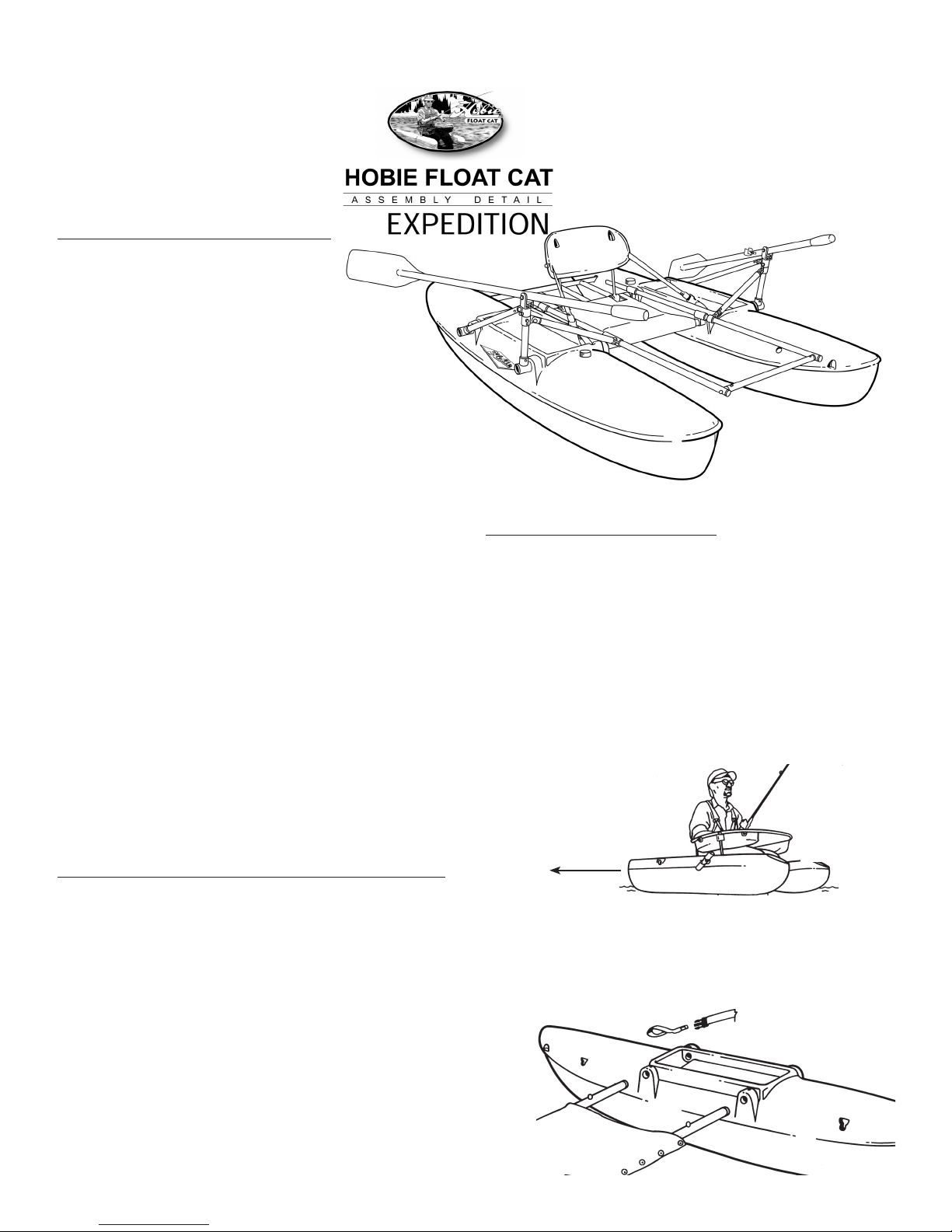
FLOAT CAT 75
EXPEDITION
ASSEMBLY AND OPERATIONS MANUAL
WARNING
Read Operations Guidelines before using.
Always wear USCG approved floatation devices.
Always wear wader safety belt.
Always attach tether while operating.
Do not operate in rapids.
Do not operate in high wind conditions.
ALWAYS USE COMMON SENSE.
Maximum capacity:
350 lbs. Float Cat 75
Page 2

HOBIE FLOAT CAT
OWNER’S MANUAL
Congratulations on your purchase of a Hobie Outback Float Cat! The Hobie reputation for exceptional
design, high quality materials, and professional service will ensure you years of pleasure.
The Float Cat was designed to enhance your fishing experience. The efficient multihull design moves
quickly over the water - a light kick will accelerate you towards your prey. The elevated seat puts you inches
above the water, keeping you warm and dry while improving visibility, accuracy, and ease in casting. The
compact shape and low weight allows you to take your Float Cat anywhere. The drink well, rod holder, and
accessories such as stripping apron with storage bags, backpack, travel bag, cooler, and rowing systems,
to name a few, makes your Float Cat a vacation destination in itself.
Hobie’s attention to detail is found throughout. The pontoons are constructed of a unique high impact,
low maintenance, polyethylene used for kayaks and industrial sanitation bins. All aluminum alloy parts
are anodized or coated to prevent corrosion. Hardware and webbing are the highest grade available. All
components are manufactured to Hobie’s specifications and made in the U.S.A. Best yet, your Float Cat
is backed by our 3 year warranty.*
From assembly to short of bringing in that record rainbow, the friendly folks at Hobie Outback are available
to answer your questions Monday through Friday at: (760) 758-9100 And they’re always curious to know
how your Float Cat performed.
Be prepared to share your Hobie Outback Float Cat with your family and friends. Or better yet, send
them to your local Outback Dealer.
Good luck fishing...and have a Hobie Day!
WARNING
READ OPERATIONS GUIDELINES BEFORE USING.
ALWAYS WEAR USCG APPROVED FLOATATION DEVICES.
ALWAYS WEAR WADER SAFETY BELT.
ALWAYS ATTACH TETHER WHILE OPERATING.
DO NOT OPERATE IN RAPIDS.
DO NOT OPERATE IN HIGH WIND CONDITIONS.
ALWAYS USE COMMON SENSE.
MAXIMUM CAPACITY:
350 LBS. FLOAT CAT 75
2
Page 3

INDEX
Float Cat Assembly . . . . . . . . . . . . . . . . . . . . . . . . . . . . . . . . . . . . . . . . . . . . . . 4-7
Cargo Rack Assembly . . . . . . . . . . . . . . . . . . . . . . . . . . . . . . . . . . . . . . . . . . . 7-8
Rod Holder . . . . . . . . . . . . . . . . . . . . . . . . . . . . . . . . . . . . . . . . . . . . . . . . . . . . . . 8
Stripping Apron Assembly . . . . . . . . . . . . . . . . . . . . . . . . . . . . . . . . . . . . . . . 9-10
Troubleshooting . . . . . . . . . . . . . . . . . . . . . . . . . . . . . . . . . . . . . . . . . . . . . . . . 11
Hobie Float Cat 75 Operations. . . . . . . . . . . . . . . . . . . . . . . . . . . . . . . . . . . 11-14
Full Size Diagrams . . . . . . . . . . . . . . . . . . . . . . . . . . . . . . . . . . . . . . . . . . . . 15-16
Page
Warranty Information . . . . . . . . . . . . . . . . . . . . . . . . . . . . . . . . . . . . . . . . . . . . 12
3
Page 4
Hobie Float Cat
Assembly
FLOAT CAT 60/75 PARTS LIST
Two pontoons
Two black plastic vent caps
Two aluminum crossbars with snap buttons
One plastic molded seat back
Two 10” aluminum seat posts with plastic C clamps
Two seat post screws 3/4” Phillips
One seat back adjustment system:
One 1”x56” nylon webbing straps with male buckles
Two 6” sewn webbing loops with female buckles
One 3” sewn webbing loop with female buckle (buckle for
cooler accessory)
One black mesh grommeted seat bottom with blue foam
wedge cushion
Three black seat lacings: two short and one long
One safety tether leg strap (Not Shown)
Rowing System Parts List
Four footrest hangers: black plastic piece with 1 1/4” and
7/8” holes at 90 degrees
Two oarlock frames: tripod hinged 7/8” tubing with
receptacle push button inserts
One footrest: two 48” lengths of 7/8” tubing with strut
attachment tabs one 18” length 7/8” tubing with
connectors & stainless steel screws
Two two piece oars with clips and attached oarlocks
Two lynch pins
FLOAT CAT 75 ASSEMBLY INSTRUCTIONS
STEP 1- Pontoon Placement
Note: The seat faces the rear or aft of the boat
(sometimes referred to as the "stern"). The front of the boat is referred to as the "bow". Float Cats are paddled
or rowed with your body facing aft (with your back to the direction of travel).
On one side near each end of the pontoons are two indentations.
Assemble with these indentations on the inside, facing each
other. The bottom of the pontoons (the part in the water)
are exactly the same. Forward (bow) and rear (stern) are
established by seat installation: Installation of the second crossbar
through the stern 6" loop (step 3 below) establishes the rear
aft crossbar.
Forward / Front
Bow
4
Aft / Rear
Stern
Page 5

STEP 2- Vent Caps
Installing vent caps (2) as supplied creates a water and air tight seal. Screw caps onto threaded holes on top of
pontoons.
Caps can be installed to self vent for altitude and temperature changes. To self vent, remove the clear plastic cone inside
each cap by prying out with a small screwdriver. The cap will not completely seal and venting will take place as long as
the cap is not over tightened. The plastic cones may be reinserted. Temperature and air pressure changes may cause
contraction of the air inside the pontoons, possibly resulting in dents in the pontoons. Pontoons may become hard as air
pressure increases inside. In either case, these conditions do not affect the strength or integrity of the boat. Loosen and
tighten caps periodically to equalize the air pressure.
STEP 3- Crossbar Installation
Insert one crossbar from the inside (indentation side) into
molded opening. Depress snap button and continue sliding
crossbar through. As the crossbar enters the outside molded
opening the snap button will pop into the first snap button
hole. When inserting the rear crossbar, make sure that it runs
through the 6” webbing loop with the female buckle. You’ll
want to do the same with the front cross bar, but note that
there is no webbing strap for the bar to go through.
Trough
STEP 4- Footrest and Cargo Hanger Installation
It is important to install the hangers prior to placing the two hulls together. Slide each of the hangers onto the
front and rear cross bars by depressing the snap buttons. There are a total of four hangers that go on the rear crossbar
and two that go on the front (the other three hangers will go on after the seat is installed).
1. Place one hanger on the rear crossbar. You must have the longer off-set part
of the hanger above the crossbar facing the stern of the boat (see diagram to
right).
Stern of Boat
2. The hangers on the front crossbar will go in different directions. The hanger closest to the hull
will have the off-set section above the crossbar facing the bow while the inner hangers will have the
off-set section on the bottom of the crossbar facing the bow (see diagram to right).
Hull
Bow of Boat
STEP 5- Seat Bottom
Locate mesh seat bottom (Item 8). The blue foam wedge inserted in the seat sleeve has a black X on one side.
With the X facing down, and Velcro edges facing up, slide the seat over the rear crossbar (reminder that rear crossbar
has been defined by the bar going through the webbing) by inserting the crossbar into the seat sleeve between the
thick edge of the foam wedge and the mesh. The thick edge of the foam wedge is cut in the shape of a half circle
to ensure a snug fit.
STEP 6- Final Hanger Installation
Slide the remaining cargo rack and footrest holder on the crossbars just past the snap buttons. Be sure to follow the
same pattern as shown in Step 4 in their relation to the hull. Remember that two hangers will be installed on the
front crossbar and one on the rear bar.
STEP 7- Final Framing
Insert exposed ends of crossbars into molded openings in second pontoon just far enough to expose crossbar in trough.
Place second 6” webbing loop in trough and slide the rear crossbar through the loop. Depress snap buttons and slide
crossbars until snap buttons pop into place.
5
Page 6
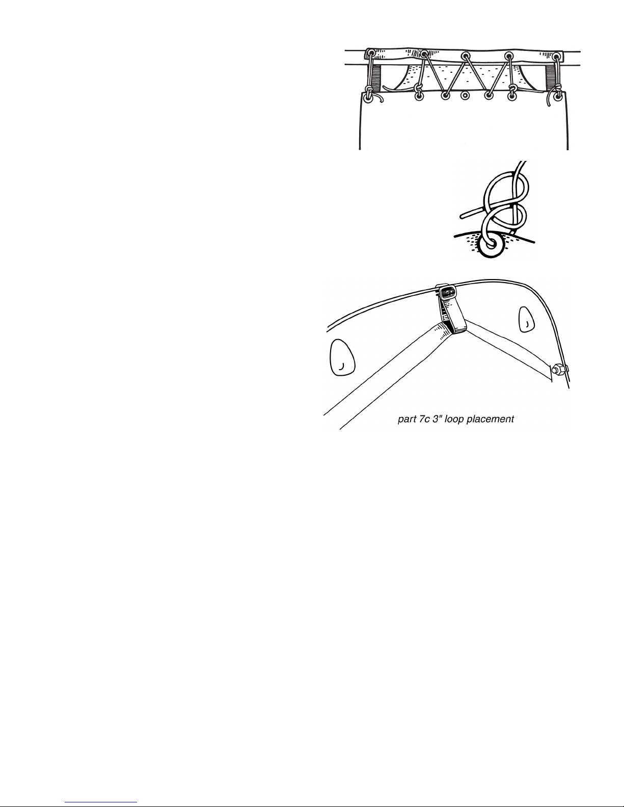
STEP 7- Seat Bottom Lacing
Locate the two short and one long black lacings (Item 9). Flip
pontoons over, vent caps facing down. Using the two short
lacings, tie a double half hitch at each outer grommet of the short
flap. Pass lacing over crossbar and up through opposite outside
grommet located on the long flap. Pass lacing back and down
through the opposite grommet. Tie a double half hitch around all
lacing. Using the long lacing, start at one end with a half hitch
and lace grommets together as diagrammed. NOTE: Center
grommet on flap is for the backpack system and should not
be laced.
STEP 8- Seat Back Preparation
Locate black plastic molded seat back (Item 4), 10” aluminum posts with
plastic molded C clamps (Item 5), and two 3/4” Phillips head screws (Item 6).
Insert screws into the recessed holes of seat back. Insert seat back posts
up through holes in flanged bottom edge of seat back and thread posts onto
screws. Snap molded C clamps onto forward crossbar where cutaways in
seat bottom reveal crossbar.
STEP 9- Seat Adjustment System
Locate 3” loop with buckle and the 56” strap with two
male buckles. Flatten the 3” loop and pass upwards
through outside slot located on the top flange of the
seatback. Pull snugly until stopped by buckle.
DOUBLE HALF HITCH
Insert flattened loop down through inside slot. Remove male
buckle off end of 56” strap. Locate slots on sides of seatback
adjacent to white nylon fittings. Insert webbing from the front
through slot. Pass webbing between seat back and seat
posts, up through 3” webbing loop, and out through opposite
slot. Replace buckle on end of strap. Snap male buckles into
female buckles located on 6” loops previously installed around
crossbars. Adjust length for comfort.
STEP 10- Safety Tether
Locate safety tether. Pass looped lacing end around rear crossbar on either side. Pass Velcro end through loop and
pull to secure tether onto crossbar.
STEP 11- Footrest Installation
1. Locate 18” and two 48” lengths of tubing. Remove screws from the 18” tubing and insert plastic end into 1/2” hole
in 48” lengths. Secure with 1 1/2” screw through 1/4” hole, making sure half round seat is completely seated against
48” tubing. When footrest is not inserted into foot rest hangers it should be disassembled; the horseshoe shape allows
for substantial leverage and can break.
2. Insert footrest evenly into 7/8” opening on hangers until all four hangers are supporting the footrest. Adjust footrest
to desired length. Secure by inserting lynch pins through holes in footrest and hanger. Snug strut attachment tabs
up against footrest hanger.
6
Page 7

STEP 12- Oarlock Frame Installation
Snap hinged oarlock frame into receptacles on sides of pontoons
with the short upright tube in receptacle nearest the stern and the
long tube nearest the bow. Attach strut to strut attachment tab
with screw and nut supplied.
Oar Assembly
Insert shaft into blade, depress snap button, continue until snap
button pops into place.
Oar Alignment
Oars are marked right and left. This is based on right and left
while seated in the boat. Insert oarlock into 7/8” opening on top of
oarlock frame. Oar handle should be away and blade should be
close before it will drop in place. Rotate oar until oarlock drops
down flush to top of opening, Rotate oar handle to rowing position
locking the oar down. To remove, rotate oar nearly 180 degrees
from rowing position. To determine if correct oar is in proper oarlock, oar blade should be 90 degrees to the
water while the oar is straight out from the side of the FLOAT CAT.
Oar Clips
(1" posts with plastic C-clamps attached) To install on oar, simply insert 3/8" post into 3/8" predrilled recess
located near oarlock. Secure with 1 1/2" screw. Position opening in "C clamp perpendicular to shaft and
tighten. Use the oar clip to snap the oars onto the crossbars when not in use. Lay the oar flat on the
pontoon deck and snap clip onto crossbar where exposed in the trough on top of pontoon.
**Warning**
All hinged and molded joint parts of the Float Cat Rowing System are designed and made specifically for
use on the Hobie Float Cat. The rigid structure of the Float Cat is used to complete the rowing system
for maximum strength. Do not twist parts into non intended positions while installing or removing the
Float Cat Rowing System.
STEP 13- Cargo Rack Assembly
Your cargo rack may already be completely assembled. If this is the case, proceed to Installation
instructions.
1- Remove the screws from all of the threaded connectors.
2- Insert the end of the 17" piece of tubing into the 1/2" hole in the cross piece of the partially assembled
rack.
3- Position the 17" piece so the 1/2" hole is facing the threaded connector on the short cross piece of the
partially assembled rack. Insert the threaded connector into the 1/2" hole.
4- Secure both threaded connectors with supplied screws. Repeat process with second 17" piece to
complete assembly.
STEP 14- Cargo Rack Installation Instructions
The cargo rack hangers should be on the inside, closest to the seat, of your footrest hangers.
1- Take the assembled rack and slide the ends, with 1/4" holes into hangers. The hangers must be on top
of cross bar for Float Cat 60 and beneath cross bar for Float Cat 75.
2- Secure with lynch pins.
7
Page 8

3- Push ends of long cross piece into indentations in pontoons. The cross piece will snap into place. Push hard
to install and pull hard to remove; you will not damage the boat. The rack should sit flat if hangers were installed
properly
Rod Holder
Fly Rod or Spinning Reel Adjustments
Your rod holder is designed to carry either a fly rod or a spinning reel. A rod keeper pin is attached by a 10/32 screw
found on the flat side of the rod holder. The pin can be moved to the adjacent hole for use on the opposite side of your
Float Cat. This pin must be removed for use with a fly rod and left in place for use with a spinning reel.
Cradle Positions
Pull out on the rod cradle to adjust your rod holder to different positions. Your rod cradle adjusts for either side of your
Float Cat and from horizontal (rod lies flat), to two trolling positions and to vertical.
Warning
When using the rod holder while trolling a very large strike could adjust the rod holder to the flat position. A rod
tether is recommended.
Seat Pad Cushion
The foam inside the seat pad is cut thinner where the pad wraps the crossbar. Locate the thinner portion. Align Velcro
strips on seat with Velcro strips on mesh seat bottom and press into place.
Hull Bag
Remove male buckles from webbing straps. Thread straps under both crossbars. Replace buckle and adjust length.
8
Page 9

Hobie Float Cat
Stripping Apron Assembly
(SEE ALSO: Large Diagrams Pg. 17)
Stripping Apron Parts List
Frame Rods:
J-1 fiberglass rod with hinge and ferrule
J-2 fiberglass rod with hinge and plain tip
Apron:
K-1 nylon storage bag with plastic hook and mesh
K-2 nylon storage bag with D ring
L two 7” aluminum apron support posts with molded
plastic C clamps
Hardware:
M four clevis pins with split rings
N two washers
O two eyebolts with nuts
P two Phillips head screws
Q two metal apron clips
Required tools: One large slot head screwdriver, one medium Phillips head screw driver
NOTE: Right and left references assumes a seated position facing aft.
J1
K1
K2
J2
Stripping Apron Assembly Instructions
STEP 1- Insert eyebolts (O) from outside seatback, through white
nylon bushings located on either side of seatback. Secure each with nuts. Eyebolts will spin freely in bushings.
STEP 2- Locate K1 and K2 and separate by undoing all Velcro edges and unhooking black plastic
hook on K1 from D ring on K2.
STEP 3- With Velcro edges completely unattached and bag facing zipper up, grasp K1 by grommeted tab and insert
ferrule end of J1 into the webbing sleeve along the curved edge of K1, bending rod as needed. Slide rod through sleeve
until grommeted tab can be inserted into hinge and lined up with the first hole (hole A) of hinge. Secure with clevis pin
and split ring. Repeat procedure with K2 and J2.
(SEE ALSO: Large Diagrams Pg. 17)
9
Page 10

STEP 4- Grasp K1 with zipper facing up and insert eyebolt on left side
of seatback into hinge and align with hole B. Secure eyebolt to hinge
with clevis pin and split ring. Repeat procedure with K2, securing hinge to
eyebolt on right side of seatback with clevis pin and split ring.
STEP 5- Seated between apron rods J1 and J2 and with Velcro
separated, pull webbing sleeves back along each rod enough to expose the
ends. Grasp exposed rods near ends, pull the rods towards you, and insert
J2 into the J1 connecting ferrule as far as it will go.
STEP 6- Remain seated. Reach back to the hinge on each side of the
seatback. Wrap your fingers around the webbing sleeve next to each hinge.
Slide your hands along the webbing, gently stretching the webbing back over
HINGE PLACEMENT
the rods. Locate the connecting hook on K1 and the D ring on K2. Insert
hook into D ring. This is a tight fit. Pull mesh over lap and attach all Velcro
edges. If edges do not line up satisfactorily, separate edges and remove hook from D ring. Slide hook down it’s
attachment cords as far as possible. Untie stop knots in cords and retie further down. This shortens the hook connector
lead. Reconnect the hook onto the D ring. Pull mesh back into position and test Velcro alignment. When satisfactory,
separate Velcro edges, flip entire assembly over the head (much like a child’s highchair), and exit the Float Cat.
STEP 7- Locate L, P, and Q. Using a large flat head screwdriver, spread the open end of clip (Q) approximately 1/4”
further open. Locate grommet near edge of one storage bag. Install clip over edge, aligning hole in clip over grommet
and snapping into place. Repeat for other side.
STEP 8- Insert tapped end of apron support post up through webbing tab on side of storage bag. Place washer over
exposed screw threads and thread support post onto screw. Align opening in C clamp (on bottom of support post)
parallel with crossbar and tighten screw with screwdriver. Snap C clamps onto crossbars where they are exposed in
the troughs on top of pontoons.
STEP 9- Apron support posts can be easily released by angling to the left or right and pulling up.
10
Page 11

Trouble Shooting
Snap Button
It is possible for snap buttons to get stuck inside the crossbars. This usually occurs because a tool smaller than 3/8"
diameter has been used. When pushing snap button down, always use a tool with at least a 3/8" diameter (or your
finger). Do not push button below aluminum surface.
Stuck Snap Button
STEP 1- A swift hit on the cross bar with a screw driver handle will snap the button into position. Place a pocket
knife, fingernail file, or a thin blade in the snap button hole and pry button back into alignment. If unsuccessful,
continue with step #2.
STEP 2- Pry off end cap of crossbar with a thin, small screwdriver. If snap button is stuck down on the outer side of
hole. Find something fairly stiff that will fit inside the tube and push snap button slowly into position. Do not push past
hold. Button should snap into place. If not, return to step #1.
STEP 3- If snap button is stuck down innerside of hole, use a wire hanger and bend a hook in the end. Slide into inside
of the tube past snap button and pull past hole. Push into place according to step #2.
Hobie Float Cat Operation Guidelines
Written by Larry Tullis, Professional Outdoor Writer
The Hobie Float Cat 60/75 has been designed for your stillwater fishing needs. It’s rigid hulls eliminate the need
for pumps, pressure checks, and patch kits. The compact design allows easy transport on cartop, in trucks and in
sport-utility vehicles. It can also be quickly disassembled and stowed in our travel bag for storage or airline travel.
The tough, molded polyethylene hulls are designed to slide through the water easily (with fins or oars as propulsion)
and to keep the angler elevated just above the water. This increases speed, visibility, warmth, casting clearance and
fin clearance (weedbeds, shallows etc.). It’s not just a step above float tubes, Hobie has created a new class of
water craft for the angler.
These operation guidelines were written by Larry Tullis, angling author, fishing guide and lecturer. His experience has
been tapped for the benefit and learning of Hobie Float Cat users. Please follow safety and use recommendations
for best performance of your Float Cat 60/75. These techniques can all be learned in one day but will take time to
perfect. Have fun.
Stability: Your Float Cat is very stable, but as with all small boats, you must have your weight centered and always
be aware of tipping over. Your boat can tip and you should always be prepared with a personal floatation device.
We recommend that you take your Float Cat into a swimming pool and learn all about it’s buoyancy, stability and
general characteristics. Flip your Float Cat over so you will be aware of exactly how stable it is and what you need
to be prepared for.
Transportation: We recommend you carry your Float Cat to the water by reaching your arm between the seat back and
bow crossbar and grasping the stern crossbar, lifting the boat up under your arm. Your Float Cat is easily transportable
on car roof racks, bike racks, utility vehicles, and also fits disassembled into most midsize vehicle trunks. By unclipping
the seat strap and pulling on the seat back, you can completely remove the seat back and apron for easy transportation.
When ready to use the boat simply snap the seatback on to the cross bar and reconnect the seat straps.
Entry: To enter the Float Cat, completely detach mesh at velcro and flip ring over backrest so the ring is resting
on tips of bow. Make sure zippers on apron bags are closed so you will not lose any valuable gear. Sit down on
seat and put your fins on while sitting in the boat, This will make walking in and out of the water safe and easy. Flip
ring back over your head, bunching mesh to front of ring. Snap ring support posts onto rear crossbar by pushing
straight down. Reattach mesh to velcro. Always enter and launch the Float Cat in knee deep water in a manner
that you can easily sit down.
11
Page 12

Tether: Always use a tether so your Float Cat will not drift away from you. All it takes is a light breeze. Secure
tether to your calf just below the knee.
Exit: To exit, position your Float Cat into shallow water. Reach down to tops of apron support posts and tilt post in
same direction, pushing ring to one side while pulling upward. Posts will snap off of crossbar. Detach mesh apron
from velcro and bunch to front of ring. Flip apron over your head, making sure hull bag zippers are closed. Ring
will sit on bows of boat. Take off your fins and stand up. Do not detach tether until on shore so you will not risk
losing your Float Cat.
Rod Holder: Your rod holder will snap into the outer molded-in accessory attachment holes. Adjust up and down by
pulling out lightly and twisting. Remove pin for use with fly rod.
Pontoon Material: Your Float Cat is manufactured out of rotationally molded polyethylene. This material is extremely
durable. It is the same material used on most kayaks and industrial sanitation bins. Although it is a very tough material,
if left in hot weather with pressure applied to the pontoon in small areas, the pontoon may develop a dent. However, the
material has a memory and in time, any dents will come out. In short, do not store your boat with heavy objects resting
on or against the pontoons. Your pontoons could also develop dents with temperature and pressure changes. These
dents will not cause any structural damages, they are not unusual and will return to their original shape.
Note: Due to the manufacturing process there may be slight color variation throughout the product. These are color
variations, not defects. To maintain the lustrous color of your pontoon, do not store Float Cats in the sun for extended
periods of time. The pontoon and bag colors will fade. Fading is not covered under warranty. To shine or clean your
Float Cat we recommend Lemon Pledge.
Safety Precautions
• Always wear a US. Coast Guard Approved Flotation Device. As with canoes and kayaks, there is a danger of falling
overboard. Always keep your weight centered. Flotation devices are mandatory for your safety.
• Your Float Cat was designed for Class 1 water or less. It was not designed for rough water, rapids, or high wind
conditions. Always use common sense and take weather, wind and water conditions into account before using
your Float Cat.
• Use common sense when using waders. Always wear a wader safety belt to keep water from entering your waders in
case you need to get off your boat or you end up in the water.
• Always attach the supplied tether to yourself so you will never get separated from your boat.
Suggested Additional Equipment
Waders: Use chest or waist-high waders. Neoprene is safest and best for cooler waters and optional in warm water.
Life Vest: Wear a life vest (required by law in most places).
Fins or oars: Use standard float tube style fins and/or Float Cat Rowing System for propulsion.
For Emergencies: Ping-pong paddles (for emergency propulsion in case you lose 1 or both fins), Parachute
Cord (for towing or securing gear), whistle (for alerting boats), first-aid kit in watertight case, personal
medications, sunscreen, drinking water, wide brim hat, rain jacket, warm gloves, hand warmer, extra pair socks.
For fishing (optional): Rod & reel, marker buoy, float-tube anchor, fish finder, personal tackle (flies, lures, leader,
weights, extra spools etc.), spare or second rod, landing net, needle nose pliers, lunch.
12
Page 13

Entering Your Float Cat
1. Make sure your Float Cat has been assembled properly and double check all connections to assure they are locked
in properly for initial assembly, see assembly instructions.
2. Carry Float Cat to lake shore. Never attempt to use your Float Cat on moving waters. It’s present design is specific
to stillwaters. Set Float Cat down on lakes edge far enough on land to prevent the wind from blowing it into lake. Stow
gear and place rod in rack. Check floatation vest.
Maneuvering With Fins
The pontoons are designed to turn easily and also to track well while
under power. Practice these three basic maneuvers until you feel
confident before venturing far from your launch point. With experience,
you can cover lots of water and use subtle variations to make your Float
Cat perform like an extension of yourself. Fins are the primary power
used for fishing but oars can help you cover more water in a shorter
period of time. (see Maneuvering With Oars)
Basic Kick: Now you are ready to move into deeper water. From a
comfortable sitting position, push yourself off shore (backward) with your
feet. Begin kicking your fins with a scissor kick, similar to swimming,
pivoting at the knee. If you are unfamiliar with fin powered water craft,
spend a few minutes kicking parallel to shore, in shallow water, until
you feel comfortable.
Power Turns: To steer while moving backwards, aim your fins to one
side or another; right to turn right and left to turn left. Remember to
aim with your back. Look back occasionally to see that you are going
towards you target and steering clear of obstacles.
DROP BACK AND
START KICK
FINISH KICK AND
DRAW BLADE
STRAIGHT BACK
Pivots: To pivot on axis, sweep one or both fins in a circular motion clockwise or counterclockwise. Your Hobie Float
Cat should easily pivot 360 degrees from a stopped position. If not, practice!
Fishing Techniques
Casting Platform: When you are ready to fish, stop the Float Cat and use the craft as a casting platform. If you have
a stripping apron, it can be use to put fly line on while fishing and a table for tackle rigging or fish de-hooking. Casting
is generally done anywhere from directly ahead to 90 degree angles from the angler. To fish comfortable, pivot until you
face the cast direction. Find the water type that holds the most fish and then work those areas carefully. Small float tube
anchors can be used to hold position and prevent
wind-drift. Throw out a small marker buoy to mark your open water hotspot. A marker or an anchor will keep you
from drifting away from your desired location.
Trolling: Trolling flies or lures from your Float Cat can be quite productive and helps find new hotspots. Use your fins
for slow trolling or the oars for faster trolling. The rod holder can be used for lure trolling. With flies it is best to hand
hold the rod, with the rod tip aimed directly at the fly for best feel and strike detection. A combination of slow trolling and
a slow retrieve often does well and covers a lot of water.
13
Page 14

Using The Wind: Wind can cause you problems until you practice these simple techniques for fishing from Your Float Cat
in the wind. Always watch weather conditions and stay close to launch point in high winds or heavy storm conditions. If
the wind get too strong to kick against, move to nearest land, wait out wind, or walk back to vehicle. Never let yourself get
blown across a large body of water. You can often find a sheltered bay to fish even in heavy winds.
1. In breezy conditions, keep your back into the wind and use a slow kick to hold position during a retrieve. A small
anchor will also keep you in place without having to keep your back to the wind.
2. Drift with the wind for slow trolling. Don’t get blown too far from the launch point. Sitting side ways to the
wind will make the boat drift slower.
3. Cast and retrieve at a 90 degree angle to the wind as the wind drifts you. You can cover open water or a
shoreline easily this way.
4. The wind often concentrates your game fish’s food on the downwind side of the lake or on the downside of a point of
land. Where food is concentrated, so will your quarry.
Maneuvering With Oars
The oar system available for your Float Cat is ideal for covering lots of water fast or for trolling. Fins are usually used in
addition to the oars, fins for fishing and oars for distance travel.
Power Stroke: Before leaving shore, make sure oars and oarlocks are setup properly. The blades should be vertical
when the oars are straight out to the side. Raise your fins to the surface or rest them on top of the pontoons or on the
optional footrest. Move your oar grips forward then raise oar handle to lower the oar blade into water. Pull towards
you with even pressure. The Float Cat will immediately move backwards. Lift oars from water and repeat to travel any
distance. Most distance travel is accomplished with this stroke.
Practice until you can track backwards in a straight line. To go straight, even pressure is required for each oar stroke.
Vary the pressure on one oar slightly to make a small direction change.
Turning: Now, stop and learn to pivot. Sink one oar into water at a 90 degree angle to hull and hold. Use a regular
oar stroke with the other oar. You will immediately begin to pivot. When you reach the desired angle, pull evenly
with both oars to propel yourself backwards.
Next, do a power turn. Start rowing backwards in a straight line and then drag one oar as you continue to row with the
other. The craft will immediately turn towards the side with the dragging oar.
Push Stroke: When you want to go forward (mostly to position yourself), use the opposite of the power stroke. Lift your
fins or trail them under the sear as you push with the oars. This stroke is not as efficient as the power stroke but is ideal
for positioning yourself (sneaking up to a weedbed, a shoreline feeding land, some waterbirds etc.).
Do’s & Don’ts
Do- Learn basics first, use fin tethers, carry emergency gear, wear a life vest, check Float Cat connections, sit
to install fins, use waist or chest waders, keep back against backrest, watch where you are going, be courteous
to other anglers.
Don’t- Use on moving water, sit on front edge of seat, travel through motorboat routes, use in severe winds, try to stand
on kickboat, use without life vest, overload (250 lb max 60" and 350 lb max 75"), crowd other anglers.
14
Page 15

15
Page 16

16
Page 17

Warranty
Hobie Outback warranties it’s Float Cat products to be free of all defects in material and workmanship for
the period of Three years from date of purchase. Upon receipt and inspection Hobie Outback will repair or
replace at no charge any boats returned during the warranty period that are found defective. Please do not
return the product without our prior authorization. If necessary repairs are covered by warranty, we will pay
return shipping charges to any destination within the United States and Canada.
For the warranty to be effective, warranty card must be mailed with a copy of sales receipt. None of the
exclusions may apply. All factory repairs after the three year warranty period carry a 90 Day Limited Warranty
subject to exclusions and limitations as listed.
To enforce warranty or obtain repairs after limited warranty period, please contact us at (760) 758-9100
or by Fax at (760) 758-1841, and we will instruct you to either return the product to the company or
how we can replace parts as needed. You must at your expense include postage, shipping charges, and
insurance costs.
Warranty Exclusions
This warranty does not apply under the following circumstances:
• If the product has been serviced or repaired by anyone other than an authorized Hobie Dealer.
• If the product has been altered, adjusted or handled in a manner other than according to the Owners
Manual furnished with this product.
• If any defect, problem, loss or damage has resulted from any accident, misuse, negligence, or carelessness.
• If color fading or damage has taken place due to excess exposure to the sun.
We reserve the right to make changes or improvements in our product from time to time without incurring the
obligation to install such improvements or changes on equipment previously manufactured.
For Your Information:
Date Purchased: ___________________
Store Purchased: ___________________
Retain for your records
Hobie Cat
4925 Oceanside Blvd., Oceanside, CA 92056
Tel: (760) 758-9100 Fax: (760) 758-1841
SALT WATER USERS
Remove and discard crossbar endcaps. Flush crossbars and rinse entire float cat after each use with fresh water.
Keep snap buttons protected with a lubricant such as WD-40TM
SAFETY PRECAUTIONS
• Always wear a US. Coast Guard Approved Floatation Device. As with canoes and kayaks, there is a danger of falling
over board. Always keep your weight centered. Flotation devices are mandatory for your safety.
• Your Float Cat was designed for Class 1 water or less. It was not designed for rough water, rapids, or high wind
conditions. Always use common sense and take weather, wind and water conditions into account before using your
Float Cat.
• Use common sense when using waders. Always wear a wader safety belt to keep water from entering your waders in
case you need to get off your boat or you end up in the water.
• Always attach the supplied tether to yourself so you will never get separated from your boat.
17
 Loading...