

Page 1

1
ASSEMBLY MANUAL
TABLE OF CONTENT
Hobie Bravo terminology............................................................................................. 2
List of the parts............................................................................................................ 3
Frame and mast ball.................................................................................................... 4
Righting line................................................................................................................. 5
Sail............................................................................................................................... 6
Mast assembly............................................................................................................. 7
Mast and sail assembly............................................................................................... 8
Mast float................................................................................................................... 10
Rudder....................................................................................................................... 11
Stepping the mast...................................................................................................... 12
Mainsheet system...................................................................................................... 13
Unfurling/furling the sail............................................................................................. 14
Boom (option)............................................................................................................ 15
Reefing the sail.......................................................................................................... 16
Page 2
2
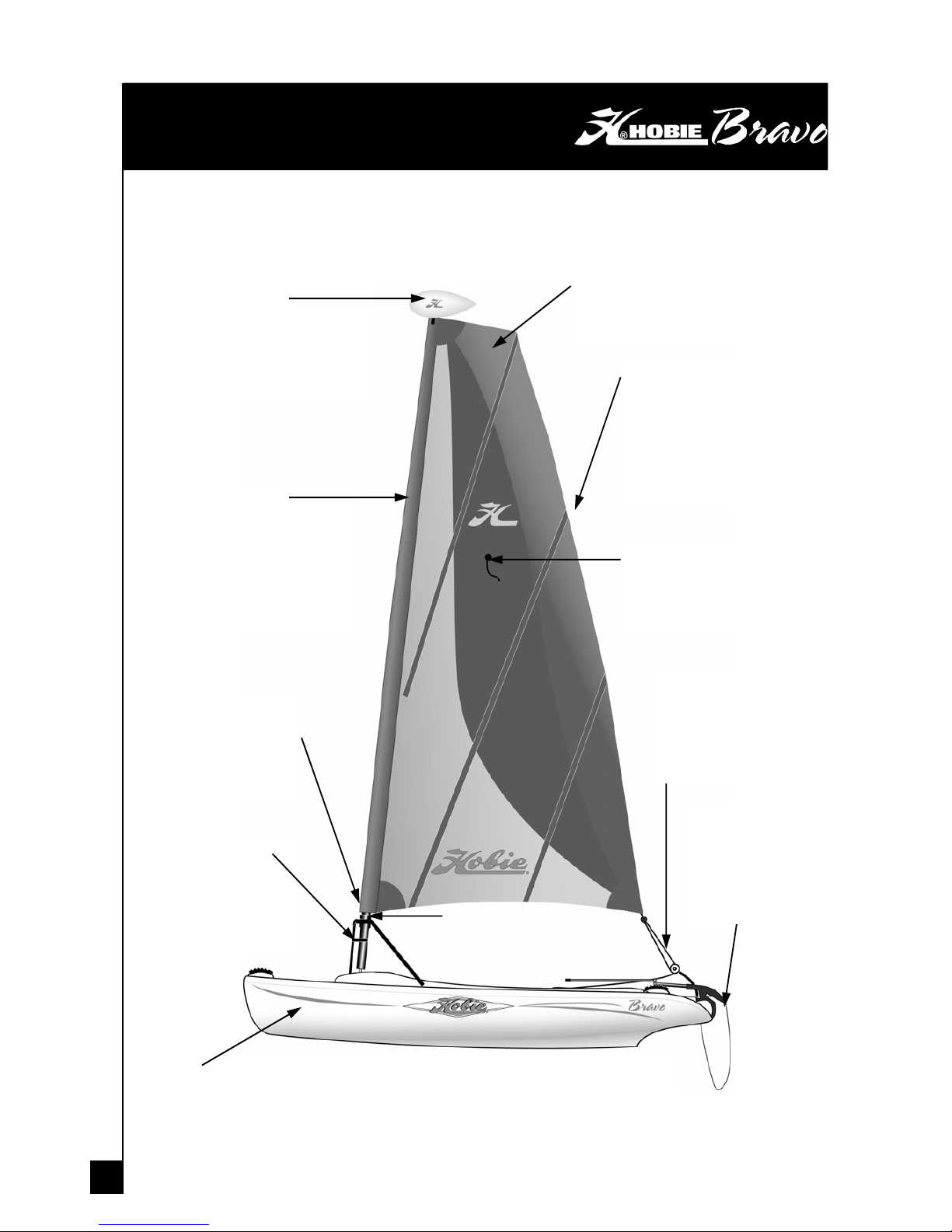
HOBIE BRAVO TERMINOLOGY
MAST FLOAT
The mast float serves as flotation
for the boat if it tips on its side and
helps to prevent turtling. Turtling is
when a sailboat turns completely
over and is upside down.
SAIL
The sail is a “square-top”
design, utilising the latest
technology in sail design.
BATTENS
Battens are long thin pieces
of fiberglass rod. These rods
give the sail stiffness and
help maintain sail shape.
The unique angles of the
Hobie Bravo battens allow
the sail to roller furl easily
MAST
The mast is a two piece, long
vertical tube designed for easy
trailering and storage. The upper
mast section features the Hobie
Comptip, a non-conductive piece
designed to maximise safety on
the water.
DOWNHAUL
The downhaul is a line
at the base of the sail
that is used to righten
the sail on the mast.
A-FRAME
The A-Frame provides a
structurally secure base
for attaching the mast
eliminating the need for
side stays
HULL
The Bravo hull is constructed from Super Linear polyethylene. The polyethylene
provides an extremely durable hull that is quite resistant to dings and scratches
RUDDER
Hobie rudders are
equipped with an
automatic kick-up
feature should you
encounter shallow water
MAINSHEET
The mainsheet is designed
with the novice user in mind.
The pulley system allows the
sailor to let the sail loose
quickly to easily reduce
ROLLER FURLER
The roller furler allows the sail to
be rolled around the mast for
easy storage and rigging.
TELL TAILS
Tell tails help to determine
the trim of the sail. They will
tell you whether you need to
sheet your sail in or out.
Page 3
3
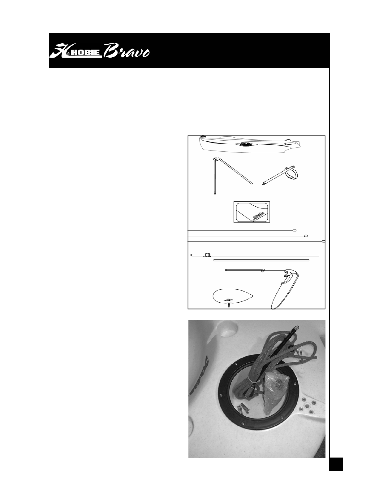
LIST OF PARTS
When opening your new Hobie Bravo, make sure to check that all of the parts are
present and that the boat is in good order. Find a good clean spot, lay out all of your
components and run through the checklist.
Large Parts
1. (1) Hobie Bravo hull
2. (1) A-Frame with vertical support
3. (1) Sail
4. (3) Battens
5. (1) Lower Mast Assembly
6. (1) Upper Mast Assembly
7. (1) Rudder with tiller extension
8. (1) Mast float
Small Parts
1. (1) Main sheet system
2. (1) Mast ball with hardware
3. (1) Bag of A-frame hardware
Page 4
4
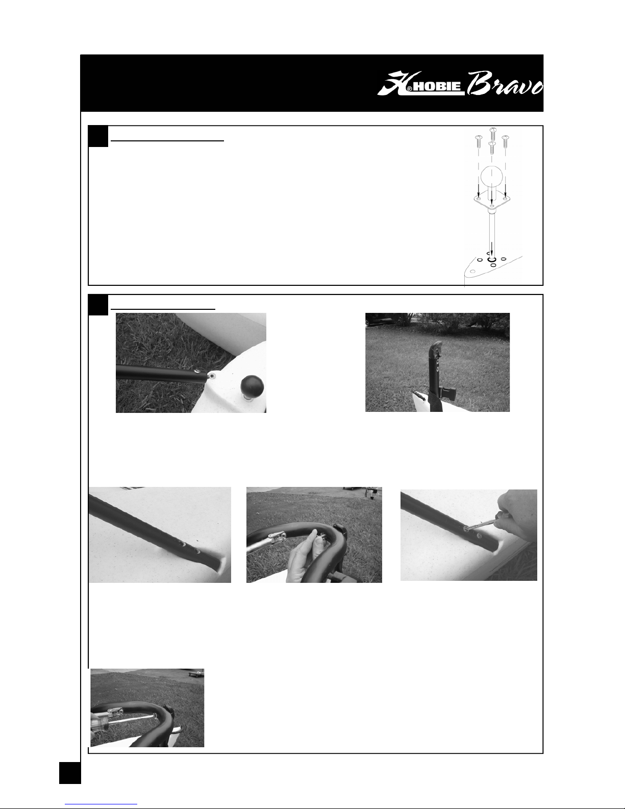
A-Frame Assembly
1 Separate the A-Frame and vertical supp ort tube from each other.
2 Insert the bottom screw of the vertical support into the threaded insert in front of the mast ball. Once
completely screwed in, be sure that the connector at the top of the tube faces toward the back of the
boat (the half-round in the connector faces toward the back). If the connector does not face the proper
direction, either tighten or loosen it to adjust to the proper position.
Mast ball installation
1 Remove packaging from the mast ball.
2 Insert end of mast ball and start to screw into the hull. As the threads go
deeper in the hull, it will become difficult to turn further. Gripping a pair of pliers
around the post will help complete the installation. Continue to screw in the
post until the plate is flush against the hull and screw holes are aligned.
3 Open the package of screws that were attached to the mast ball.
4 Insert and tighten screws into each of the holes in the plate.
FRAME
1
2
3 Place the arms of the A-
Frame into each of the
designated slots in the hulls.
4 Loosely connect the tip of
the A-Frame to the
connector on the vertical
tube. This will help hold
the end up while you align
the other holes.
5 Install the screws into each
of the A-Frame legs. Before
tightening down, we
recommend that you start
to thread each screw with a
hand screwdriver. This
helps in aligning the holes
properly, and will prevent
crossthreading of the
screws. Once all the
screws have been started,
tighten each one down with
a screwdriver.
6 Tighten the screw that attaches to
the vertical support.
Page 5
5
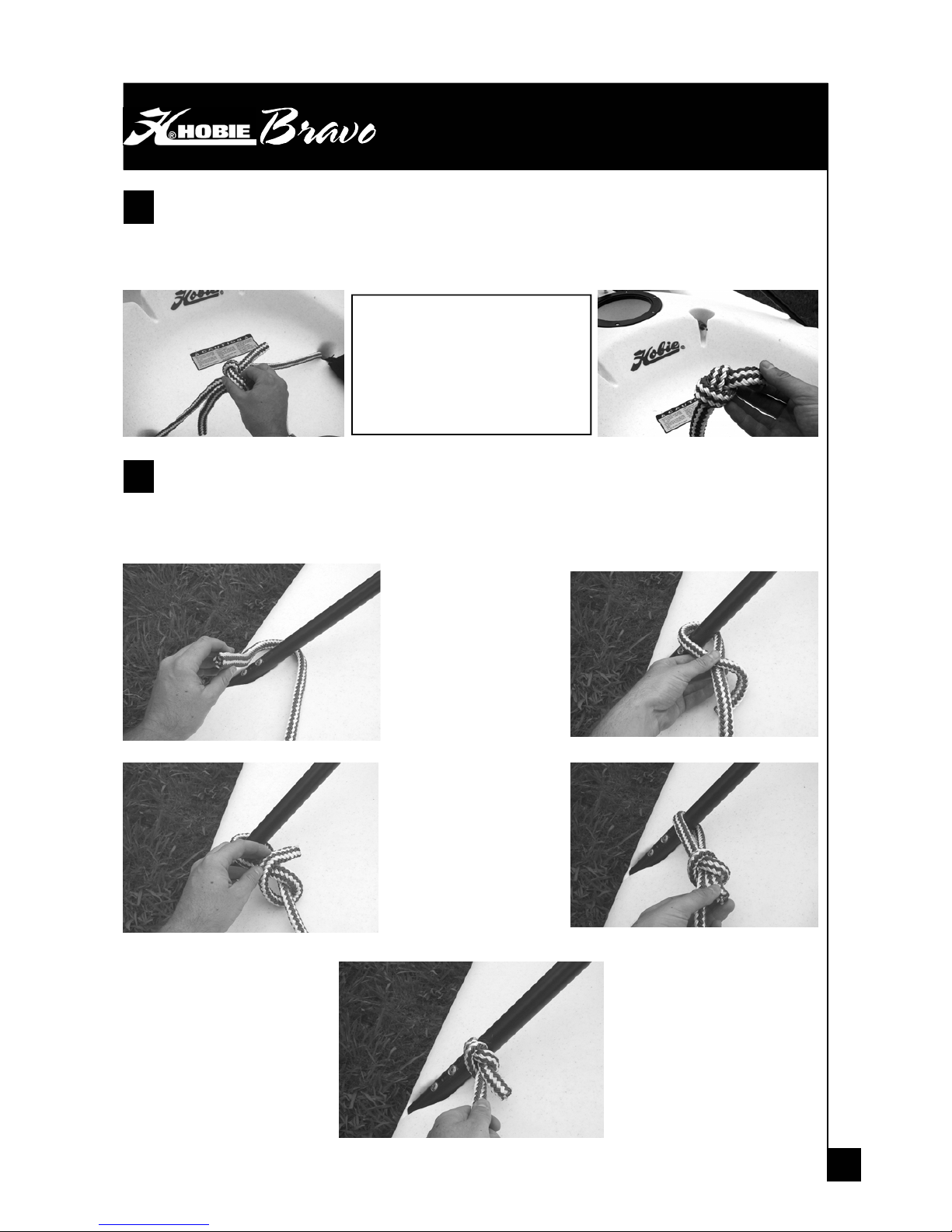
Coming up through the front scupper holes, you will find the installed righting line.
Untie the two ends of the line from each other. Be sure to hang onto the line when
untying them so that they do not fall back through the scupper holes.
RIGHTING LINE
1
Tip :
When tying one of the lines
off, put a knot at the end of
the other line to prevent it
from falling through the
scupper hole.
Use a slip knot and tie each of the ends to the base of the A-Frame. The left line
goes to the left side of the A-Frame and the right line goes to the right side of the A-
Frame.
2
1
3
2
4
5
Page 6

6
Find a large clean area where you
can lay the sail flat.
The battens for the sail are the long
white rods that are attached to the
mast. Lay them next to each other to
help identify where they go. The
longest batten goes in the middle, the
shortest at the bottom, and the middle
sized batten at the top of the sail.
SAIL ASSEMBLY
1
Carefully slide each of the battens into their proper
sleeve all the way to the end.
2
Once the battens are fully installed, use
the diagrams below to guide the lacing of
the battens to the sail. When tying in the
battens, it is important to use the line to push
the batten into the pochet. Tension each
batten so that it is well seated and removes
any wrinkles in the batten pocket.
3
Pull on line to
push batten
into pocket
Cleat off
line in
batten
Tie a small figure 8 knot in the end of the
line to prevent the batten from falling from
the sail if the line comes out of the cleat.
4
Page 7

7
MAST & SAIL ASSEMBLY
Place the top and bottom sections of the
mast end-to-end.
1
Insert the upper section of the mast
into the lower section. The end of the
upper section to be inserted has two
strips of clear tape and a notch on the
bottom. To make sure the comptip is
completely engaged, rotate the comptip
while pressing the lower section into the
extrusion until the rivet drops into the
notch.
2
Position the sail so that the bottom of the sail is at
the top of the mast.
Insert the top of the mast into the sleeve at the
foot of the sail. Gently slide the remainder of the
mast into the sail sleeve. While putting the mast
into the sail be sure that the webbing at the top is
in the saddle and the forward edge of the sail is
aligned with the forward side of the comptip
(note : the notch is located on the forward side of
the comptip).
Now that the sail is on the mast, you are ready to
put downhaul tension on the sail.
3
Top section
Bottom
section
Page 8

8
(1) Wrap the line around the post,
(2) back through the loop, (3)
around the post again, (4) pull
tight and fasten in the cleat at the
base of the sail sleeve. The goal
here is to put tension on the sail
to pull all the wrinkles out of the
sail sleeve.
NOTE : Before applying downhaul on the sail, be sure that there are no twists in
the sail sleeve. Once the tension is applied, the sail top will not rotate relative to
the bottom.
MAST & SAIL ASSEMBLY
Rotate the mast so that the knob just above the
bearing lines up with the small loop and line at the
base of the sail.
4
5
1 2
3 4
The downhaul tension may have to be adjusted from time to time.
When the downhaul tension is lost, the sail sleeve could start to
twist on the mast. If this happens, unhook the downhaul and rotate
the mast to straighten the sail sleeve on the mast. Once straight,
put downhaul tension back on the sail.
Page 9

9
Once the downhaul is attached, the mast
is no longer free to spin within the sleeve,
which allows the sail to be rolled around
the mast.
Pick up the bottom end of the mast,
leaving the top end resting on the
ground, or held by another person.
With the sail in the same orientation as
shown in the diagrams, rotate the mast counterclockwise. The sail will start to roll
around the mast. Continue to roll the sail until it is completely around the mast.
6
MAST & SAIL ASSEMBLY
After the sail has been rolled onto the mast, it will still be a little loose. Give the
loose end a pull to snug up the sail.
7
Take the blue line that runs through the
grommet in the sail and pull the knot through
the plastic hook.
8
Page 10

10
MAST FLOAT ASSEMBLY
Notice that there is about 8” (20 cm) of extra
sail and mast extending above the actual sail.
This is designated for the mast float.
1
Before placing the float on the mast, you want to
be sure that it is oriented in the correct direction.
You will notice that on one side of the sleeve
there is white stitching holding the sleeve
together. The slimmer side of the float is to point
toward the white stitching.
2
Slide the float onto the mast and clip the mast
float to the sail.
3
If you are trailering the Hobie Bravo long
distances, it is a good idea to unclip and
remove the mast float from the sail.
Page 11

11
ATTACH YOUR RUDDER
It is much easier to attach the
rudder when the handle is
unlocked. If locked, brace the
rudder blade between your feet
and pull up the handle. It may help
to bump the bottom of the handle
with the palm of your hand.
1
Rudder locked Rudder unlocked
Align the holes of the lower rudder
section over the top of the pintles.
2
Once they are aligned, lower the
rudder down so that the pintles
are fully inserted. If it is difficult to
slide down, pivot the rudder back
and forth while pushing it down.
3
NOTE : the split ring will be installed after the
mainsheet system has been mounted.
Page 12

12
Wrap the strap around the mast
and clip the two ends together.
Unwrap the furling line from the Aframe. Take the end with the loop
sewn into it and place the loop
around the knob underneath the mast
collar.
Continue to push the mast up
until the collar interlocks with
the A-Frame
RAISING THE MAST
Pick up the mast and rest
the base of the mast on
the mast stepper ball
1
When you are ready, you may start to raise the mast.
Check overhead again for any power lines that
could make contact with the mast.
When raising the mast, apply constant forward
pressure on the mast ball so that it does not pop off.
As you raise it, you will walk forward and move your hands
down the mast.
3
WATCH FOR OVERHEAD POWER LINES. NEVER RIG, TRAILER, OR
SAIL THE BOAT NEAR OVERHEAD POWER LINES. MAST CONTACT
WITH A POWER LINE COULD BE FATAL
Once it is sitting securely
on the ball, raise the
mast on your shoulders.
2
4
When the mast is all the
way up, it will require very
little strength to hold it up. Use
one arm to hold the mast up to
the A-Frame while swinging
the gate with your free hand
over the mast bearing. Hand
turn the knob on the A-frame
to thread the bolt into the gate. Be sure that the bolt successfully enters the gate
and is fully threaded in. Hand tighten all the in.
5
6
Page 13

13
Place the hook on the mainsheet line through the grommet
on the sail.
INSTALLING THE MAINSHEET
Install the end of the mainsheet
system through the hole on the top of
the rudder and place the end around
the tip of the upper rudder pintle.
1
Once the holes line up, insert the
quick pin through the holes.
NOTE : the quick pin not only holds
the mainsheet on, but also prevents
the rudder from falling off in the
event of capsize.
2
3
About your mainsheet block
The mainsheet
block provided with
your Hobie Bravo
allows you to cleat
the mainsheet for
more comfortable
cruising. To cleat off
the line, simply pull
the mainsheet into the spring-loaded cleat. To uncleat the line, a flick of the wrist with
the line in hand can usually pop it out of the cleat.
4
The red switch on the side of
the mainsheet block controls
the pulley wheel. Having the
switch pointing up prevents the
pulley from rolling backwards.
This will help you hold onto the
line if it is not cleated.
With the switch in the down
position, the pulley is free to
spin in both directions. This
allows the mainsheet to be
released quicker. We
recommend that the switch
be in the down position for
To adjust the angle of the cleat,
unscrew the three screws on
the side of the block, pull the
screws out, and adjust the
angle of the cleat. Once in the
desired position, install the
screws and tighten back up.
Page 14

14
To furl the sail, be sure that the
mainsheet is free from any
obstructions. Grab the furling line and pull
through the padeye. This will cause the
mast to rotate with the sail around it. Once
the sail is fully furled, cleat the furling line
on the cleat on the A-frame.
Sometimes, when furling, the sail will not
wrap completely around itself. This will be
fine if you are beaching for a short time.
But if it is over a long period of time or for
transport, unhook the mainsheet and wrap
the sail around itself. Run the knot of the
blue rope at the base of the sail through
the plastic hook.
The sail furling system of your Hobie Bravo makes rolling up your sail a snap.
Before you can unfurl the sail, it is important that you have the furling line running
through the padeye on the A-frame to the knob on the mast (see stepping the mast)
In order, for the furling mechanism to work properly, the sail must be rolled up on the
mast when raised. With the sail rolled and mainsheet attached, remove the blue sailholder line from the plastic hook and pull on the mainsheet line. You will see that the
furling line has been wound around the mast. If the mast does not seem to be unrolling,
check to see that the furling line has not been stopped in the cleat on the A-frame or
been caught somewhere on the boat.
UNFURLING/FURLING THE SAIL
1
2
We recommend furling up the sail
whenever the boat is not in use.
This will help prolong
the life of the sail.
Page 15

15
Notice the groove above
where the A-Frame sits
in the mast bearing. This is
the location for the boom.
INSTALLING THE BOOM
The Hobie Bravo was designed for sailing without a boom, but one can be used if desired. A boom will
get more performance out of the sail during high wind conditions. Attaching the boom is simple.
1
Align the boom clip to the groove and give a strong
push forward. The clip will flex slightly and snap
around the bearing.
2
If your sail is hooked to
the mainsheet, unhook
it from the grommet in the
sail.
3
The hook on the boom is
placed in a track. This allows
the hook to be moved for furling
and outhaul adjustments. Attach
the hook to the grommet of the
sail.
4
The line that runs the length
of the boom is called the
outhaul. It controls the location of
the clew of the sail. By pulling on
the outhaul line, it will move the
clew of the sail out on the boom
away from the mast.
5
To unfurl the sail, uncleat
the mast furling line from the
A-Frame and pull the outhaul to
move the sail out on the boom.
Once at the desired location,
cleat the outhaul line at the cleat
on the bottom of the boom.
To furl the sail, uncleat the
outhaul line and pull in on the
mast furling line. Note that as you
pull in, the boom is going to rise
6
Snap the boom vang clip to the padeye in front of the forward
storage hatch. The boom vang helps to control the amount of
upward lift on the boom. Simply pull down on the line and cleat in the
boom vang cleat when the boom is at the desired level.
7
Attach the mainsheet hook
to the padeye at the bottom
rear of the boom.
Now you are ready to sail at the
Hobie Bravo’s top performance.
Always be aware of the boom
location. Watch your head!
8
Page 16

16
Reefing the sail is typically done during high wind conditions, docking, and beaching.
Reduction of sail size helps with control, reducing sail luffing, speed, and chance of
tipping over.
To reef the sail, pull in on the furling line until you have re-gained comfortable control of
the sail. Remember to place the furling line in the cleat on the A-Frame, or the sail will
unroll whenever you pull in on the mainsheet.
Shown above are examples of two different reefed positions. Keep in mind that the
higher the wind, the more the sail should be reefed. Also, for best performance, adjust
the reefing position so that the mast float faces forward.
To get the sail to its original size,
uncleat the furling line and pull in on
the mainsheet to unroll the sail.
REEFING THE SAIL
 Loading...